Here’s a practical look at the Air/Fuel ratio sensor, how it’s different from an O2 sensor, techniques for diagnosis and replacement tips.
 A quick review of the basics
The proper air/fuel ratio is one of the key aspects of engine performance, and is very important for reducing emissions. The ECM uses sensor input to determine how much air is entering the engine, then applies logic, known as a base fuel map, to determine the injector on-time, thus the amount of fuel added to the engine. This base calculation usually comes pretty close to ideal in modern cars, but pretty close is no longer good enough to deliver the fuel economy and low emissions expected and required in today’s vehicles. Also, there are a number of variables such as manufacturing variances, engine wear, unmetered air leaks, injector condition, and fuel blends that will affect the accuracy of the base calculation.
A feedback system is employed to determine how close the base calculation came to providing the ideal air/fuel ratio, and allows the ECM to modify the ratio based on exhaust gas measurements. The feedback cycle starts when the ECM injects a pre-mapped amount of fuel based on sensor input. The exhaust sensor reports back, the ECM adjusts, the exhaust sensor reports, the ECM adjusts, and the cycle continues for as long as the engine is running in closed loop. Adjustments to the fuel map are known as fuel trim.
Feedback systems have been used on Nissan products since the late 1970s, even on some carbureted cars, so most technicians are familiar with the basics. However, until recently oxygen (O2) sensors were most often used to provide feedback. This article will cover differences, diagnosis, and service of the type of exhaust sensor used on almost all new Nissan products, the Air/Fuel (A/F) ratio sensor.
What makes A/F ratio sensors special
O2 sensors work well if the strategy is to provide the stoichiometric 14.7:1 air/fuel ratio while in closed loop. An O2 sensor will output less than 450mV when the mixture is 14.8:1 or higher, or more than 450mV when the mixture is 14.6:1 or lower. But what if you were a Nissan engineer and you wanted to run 15.5:1 to save fuel under certain driving conditions, or temporarily enrich the mixture to reduce NOx emissions? The O2 sensor is like a switch: it will read higher than lambda or lower than lambda, on or off, black or white, but no shades of gray. This is not good enough for the fuel control strategies used in modern cars.
The air fuel (A/F) sensor solves this dilemma. It measures the air/fuel ratio instead of providing rich/lean output. Some A/F sensors are capable of accurately reporting mixtures between 10:1 and 30:1, allowing the engineers a lot more freedom in fuel mapping.
The inner workings and construction of A/F sensors are an interesting study if the goal is a better understanding of how things work. However, since we will not be required to design or rebuild an A/F sensor during the course of our daily responsibilities, and an understanding of its fundamental workings is irrelevant to diagnosis and repair, our time is better spent seeking to understand what observable characteristics separate a “good†A/F sensor from a “bad†A/F sensor.
Diagnosis of AF sensor failure
The most common A/F failure is the heater. Why? Ever heard the expression “the candle that burns twice as bright burns half as long?” Well, the A/F sensor heater is one seriously bright burning candle! An O2 sensor heating element runs at about 600 deg. F., which is pretty hot. But that’s nothing compared to an A/F sensor. Its heating element runs at almost 1,500 deg. F., hot enough to melt aluminum and make steel glow bright red and bend like a noodle. Combine this very-high operating temperature with corrosive gasses and incessant vibration and it’s actually pretty amazing they last as long as they do.
Without a functional heater, the A/F sensor cannot work properly. Therefore, if you find a heater code and a performance code, always diagnose the heater code first. Many vehicles will not run the A/F performance tests if the heater test fails, but sometimes the results from a previous performance test will remain in memory, so it is possible to have both heater and performance codes stored.
Fused power is supplied to the A/F sensor heater whenever the key is in the ON position, and a ground pulse is supplied by the ECM based on MAF and RPM inputs. If engine load and calculated exhaust temperature are high enough to maintain A/F sensor operating temperature, the ECM will stop cycling the sensor.
A common diagnostic blunder is to assume the A/F sensor heater is bad based only on the trouble code. The odds are certainly stacked in favor of a bad sensor, but fuse, wiring, and even ECM-driver problems do come up from time to time, so it’s wise to check the whole heater circuit. Playing the odds may damage your shop’s reputation with your customer, or your reputation with your boss.
Before checking the heater circuit, verify that the problem that caused the trouble code is current by running a DTC confirmation. Check the manual for the vehicle-specific procedure, but typically the DTC confirmation involves cycling the key on, then off for at least 10 seconds, starting the car, and letting it idle, or idle followed by revving, then returning to idle. The heater monitor can usually be run with the car in the bay in just a few minutes. When trying to duplicate a trouble code, it’s best to use the CONSULT to monitor live data, as this will enable a check-mode that will decrease the time it takes to set a code.
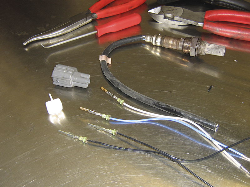
TIP: Disassemble and scavenge terminals from the O2 and A/F sensor sensors you replace. Some are male and some are female. They come in handy to make a solid DMM connection for future testing.
If a heater code resets, check the circuit. A complete heater circuit check is quick and easy. You’ll need a wiring diagram to decode the wire colors on the harness side, but the wires on the AF sensor side are often universal. Usually, the two heater wires are the same color, most often black. Which is power and which is ground/control can be easily deduced once you take measurements, as follows:
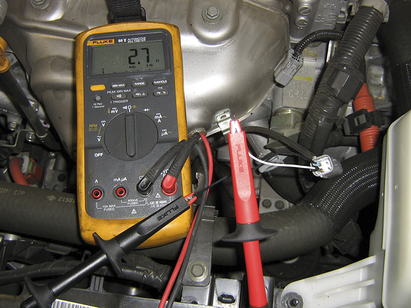
- Disconnect the sensor connector and check resist ance across the heater wires on the sensor side connector. Compare the resistance to the specification, typically between 2-5 ohms at 77F deg. F. Be sure to allow the sensor to cool before testing.
-
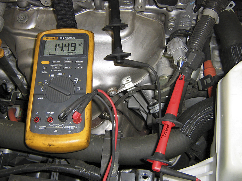
Reconnect the sensor connector and check for power at the sensor connector while the circuit is loaded. To do this, just hook up a voltmeter to the 12V+ wire at the sensor with the sensor plugged in and start the car. If you find battery voltage at the connector while the heater is on, it’s good. A poor connection or faulty relay can easily be missed if the connector is unplugged or the heater is not loading the circuit while testing.
-
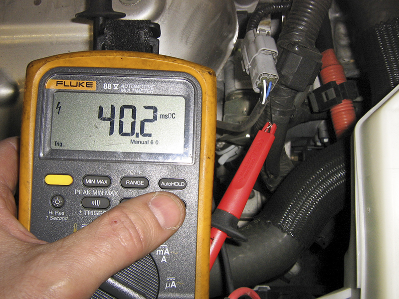
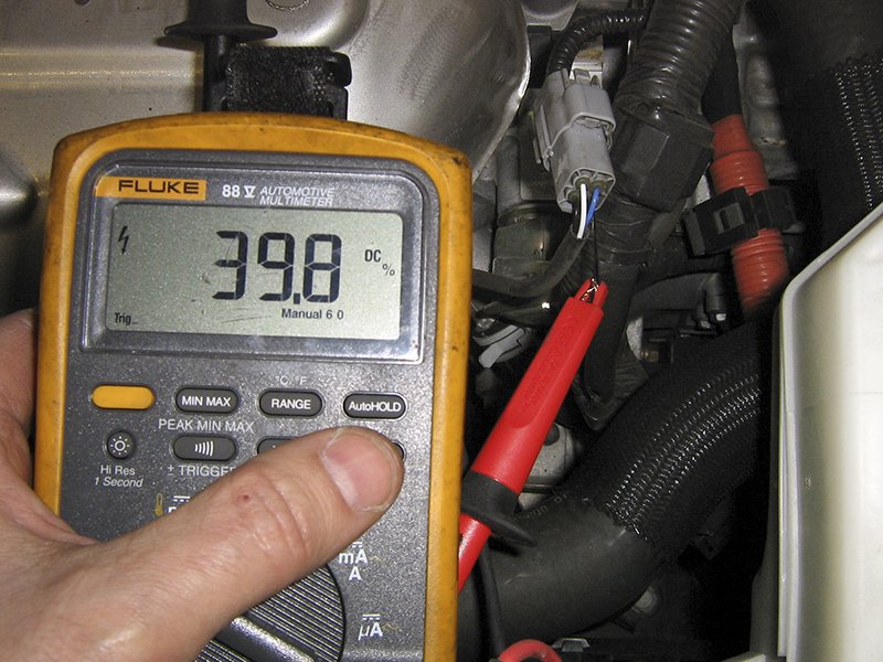
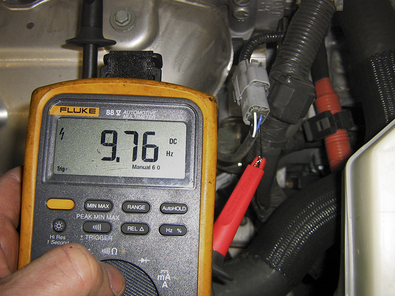
An oscilloscope will provide more information, but a DMM that can measure Hz, duty cycle, or pulse width can also be used for a quick check of ECM heater control.
Check for the ECM ground pulse at the sensor connector (still plugged in). An oscilloscope is the best tool for this test, but a DMM with duty cycle, Hz, or pulse width can also be used.
Sometimes a heater code does not reset following a DTC confirmation, and a check with a generic scan tool will reveal the heater monitor has passed. Intermittent faults can be frustrating for both shops and customers. Sometimes wiggle and tap testing will flush out the fault, especially if the problem is not with the A/F sensor, but other times the problem will need to “get worse†before it can be conclusively diagnosed.
The diagnosis of A/F sensor heater codes is not much different from that of O2 sensor heater codes, other than the lower resistance of the heater element and differences in ECM control of the heater, so many technicians find no problem in making the switch from diagnosing O2 heater codes to A/F heater codes.
However, diagnosis of the sensor output is a whole different animal, and has created a fair amount of confusion, as well as some inventive but time consuming diagnostic techniques involving jumpers, ammeters, and oscilloscopes. The truth is that other than an inspection for exhaust leaks, there is no reason to leave the comfort of the cabin. The CONSULT is your friend.
It would be foolish to diagnose an O2 sensor output from the driver’s seat. An oscilloscope is still the best way to gauge O2 sensor health. Rise time, maximum voltage, minimum voltage, and cycle frequency are still the best diagnostic tests. It would be equally foolish to attempt to diagnose the A/F sensor from under the hood. The CONSULT has all the information you’ll need.
There is a variety of A/F sensor designs, and sensor output varies depending on the vehicle. Some sensors will output 1.5V with a 14.7:1 ratio, others will output 2.2V at 14.7:1, and then there are those that will output 3.3V at 14.7:1. However, they all share something in common: they should respond rapidly and dramatically to sudden changes in the A/F mixture. The manual will have a ratio/voltage graph, so it’s easy enough to find out what the voltage should be at 14.7:1. However, to truly know what normal response should be for a particular car, you’ll need to check sensor output on known good cars.
The next time you have the CONSULT hooked up to a Nissan, take a peek at the A/F sensor voltage and snap the throttle a few times while watching the response. Depending on the car, it may be necessary to limit the number of PIDs to get good update speeds. The TPS and A/F sensor are all you’ll need. You should notice that when you snap the throttle, the sudden rush of air creates a momentary lean condition and high A/F sensor voltage. The ECM will respond quickly with a burst of extra fuel, which will arrive just as the throttle is closing, creating a rich condition and low A/F sensor voltage.
As A/F sensors age, the amplitude of their response will decrease. An A/F sensor that is setting a code will have low amplitude, maybe 0.5V peak-to-peak or less. An A/F sensor that is good will have a larger swing, maybe 2.0V or more peak-to-peak. After you’ve built your database, you’ll be able to hop in the car, snap the throttle a few times while watching live data, and then break for lunch.
If the vehicle has throttle-by-wire (and most newer Nissan vehicles do), you’ll need to drive the car to force rapid changes in air/fuel ratio. If it’s not easy to leave the bay for a quick spin, you could also use propane or large vacuum leaks to force the mixture rich or lean while monitoring A/F sensor response. Many of the newer vehicles with throttle-by-wire also have a CONSULT-guided DTC confirmation test, which makes testing even easier, because you will not need a known-good sample to compare against, nor will you need to guess at the good/bad threshold.
Replacing A/F sensors
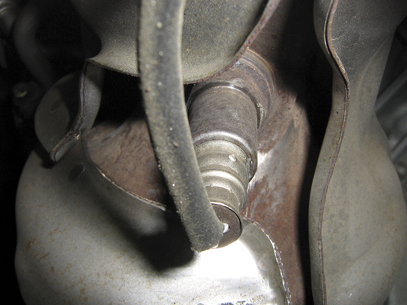
A/F sensors are pretty easy to replace when all goes well. Unfortunately, sometimes all does not go well. First, exhaust sensors can get stuck. It’s best to treat every sensor as if it’s going to be stuck. Spray it with plenty of penetrating lubricant and let it soak a bit. Use a solid sensor socket and break the sensor free with a sharp rapping motion. If the sensor does not spin by hand after it is loosened, spray it with additional penetrating oil before continuing to remove. If the threads are galled, don’t install the new sensor until they’ve been repaired. An inexpensive tool, the 18mm Oxygen Sensor Thread Cleaner (J-43897-18) can purchased from to clean the threads and condition the gasket mating surface.
Lastly, A/F sensors are a bit delicate, despite their ability to survive in a very hostile environment. Nissan says to discard any A/F sensor that has been dropped from a height of 19.7†inches or greater. Wipe the oil off your hands before installing an A/F sensor so you don’t fumble. Either that or keep the car close to the floor during the installation. When installing the new A/F sensor, use the provided anti-seize lubricant on the threads. This will help the next guy who removes the A/F sensor (maybe you!)



0 Comments