While computer controls have given drivers and passengers a safer and more comfortable trip, they of course add a greater level of complexity when diagnosis is needed. Volkswagen’s engineers have provided us with self-diagnostic capabilities and access to data with the VAG 5052. But what do we do when the vehicle won’t communicate with us?
Volkswagen is always trying to build safer vehicles. Naturally, the way it achieves this is through applying the latest technology. With computers, virtually every aspect of the vehicle can be monitored and precisely controlled. It started with electronic fuel injection back in the late 1960s, which evolved into feedback/closed-loop systems a decade later that helped make engines more fuel efficient and cleaner-running. Anti-lock brakes use computer power to help monitor the speed of each wheel, and if any wheel locked up during a panic stop the electronics manage the fluid pressure to that wheel. When electronic throttle control appeared, the computer was given the authority to over-ride driver input. Transmission control units handled shifting decisions with solenoid activation instead of governor pressure in a valve body. Computer-controlled suspensions can change ride height at speed and suspension stiffness at the push of a button.
Integration
Electronic Stability Control (ESC) was one of the first concepts that integrated all these electronically-managed systems and got them to work together in harmony. Anti-lock brakes, for instance, don’t only help prevent tires from skidding during a stop. Under hard acceleration, a tire may lose traction, but the ESC system can apply the brakes to that wheel to get it under control. What if, as an added measure of control, we reduce the throttle opening to cut the engine’s power output?
Somehow the information that the wheel is spinning out of control needs to get to the engine management system so it can cut the throttle opening. If the engine management system had its own wheel speed sensors, you would need two different sensors on each wheel. If every control unit had its own sensors for all of its inputs, you would have a very complicated system of redundant sensors.
A signal wire could be used to provide this information from the ABS unit to the Powertrain Control Module (PCM), but there is so much information all the control units need to share. For example, the Transmission Control Module (TCM) needs vehicle speed input to determine when it should command shifts, and the instrument cluster also needs this information for the speedometer. And the TCM needs throttle-position input to determine if the transmission should kick down to a lower gear for acceleration. With all this information needing to be shared among control units, a different method of inter-communcation was needed. The Controller Area Network (CAN) concept is one of the most efficient ways to accomplish this. Computers have had self-diagnostic capability for many years, but with a CAN you can read so much more information than you could by pin testing each component.
Two CANs
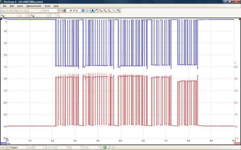
On most Volkswagen models, such as the Beetle, Jetta and Passat, you will find two CAN systems. One is the Powertrain CAN, and the other is the Body CAN. The former is made up of the PCM, the TCM, and the ABS, and it communicates at a staggering 500kbits per second. This high speed is necessary to respond to changing road and driving conditions. Each control unit distributes its information on a two-wire CAN bus. The two wires have redundant characteristics. They both communicate exactly the same information, but at different voltages. One wire is “CAN High.†This starts off at 0 volts and switches between 0 and 5 volts. The other wire is CAN Low. This wire starts off at 5V, and alternates between 5 and 0V. The two signals mirror each other as they both carry the same information.
This redundancy is important in case one of the wires develops an open or short problem. If one CAN wire were to fail, the PCM can still communicate on the other wire. But there is another reason the CAN signals are paired: They are very low-amperage signals and electrical interference can easily disturb them. Since one signal wire is switching from high to low voltage, and at the same time the other signal wire is switching from low to high voltage (remember, they mirror each other), the electromagnetic fields cancel each other out. The wires are twisted together to enhance this property. They are protected from outside electrical interference. So, it’s important to remember that if you have to repair a CAN wiring harness you must maintain the same level of interference suppression.
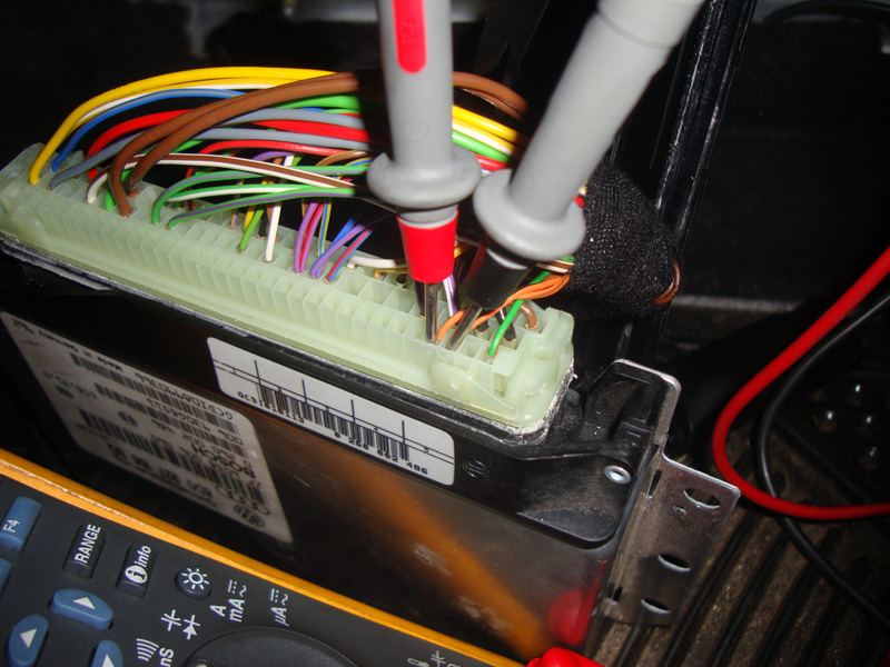
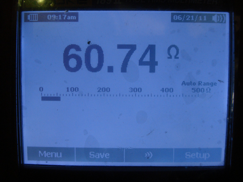
There are also terminating resistors in the CAN circuit, which serve to close the circuit. What does this mean to you? Well, if you have a communication problem between modules you are going to have to perform some tests to isolate the cause. The CAN circuit uses two 120-ohm terminating resistors in the powertrain CAN. If you have diagnostic trouble codes showing that you are running on a single wire, you are going to want to check the integrity of the CAN wiring. You can do this by simply measuring resistance between CAN High and CAN Low wires with CAN communication off. The two 120-ohm resistors wired in parallel yield a 60 ohm overall resistance. For example, you can lift the carpet on an early 1998 Passat and pull out the TCM cover. At the TCM connector you can measure resistance between pins #86 & #85. These are the CAN High and CAN Low wires. If the wiring is intact you should measure approximately 60 ohms. This is one test you can perform to check the wiring.
Protocol
All the control units on the powertrain CAN talk at 500kbits per second, but all of them cannot talk at the same time. Information would “crash†into other information and no one would understand any data. Each control unit has to follow a protocol. One control unit’s messages are placed as the most important, and another’s as the least important. In the case of the powertrain CAN, the ABS/EDL module’s messages are given top priority. The PCM’s messages are second, and the TCM’s data is the lowest. This is why a tire spinning will “relax†the throttle. Maintaining control of the vehicle during the emergency situation the ABS unit is involved in is more important than brisk acceleration. This information is traveling at a high data rate, so when the tire’s speed is under control the throttle will be applied again.
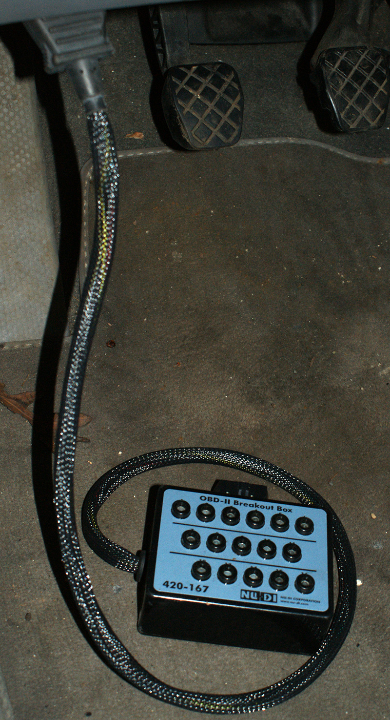
The Body CAN has a central control unit or module in the convenience system and individual door modules. Body features do not need to operate at a high data rate. Volkswagen’s body CAN communicates at 62.5kbits per second. It still communicates with a 0 to 5 volt and 5 to 0 volt switching signal on the CAN High and CAN Low circuits. You can check the CAN wiring by measuring resistance from the central control module pins just as you can on the powertrain CAN. Another test you can perform on either CAN is to “scope†the signals. Using an oscilloscope, you can tap into the CAN lines and view the messages being sent. You will not be able to interpret the data, but you can at least see there is communication going on. Your VAG 5052 or equivalent has the necessary software needed to interpret the CAN signals.
Aftermarket radio?
Once you have determined that the CAN wiring is okay and the signals are there (wiring is not shorted to power or ground), you are still going to have to figure out why you are not able to communicate with a specific or group of modules. Components such as the radio are on the diagnostic bus. Aftermarket radios do not have the same CAN diagnostic protocol the OEM radios have. An aftermarket radio can put false electrical signals on the line and interfere with normal CAN communication. If you cannot communicate with any control unit in the vehicle, one of the first things you should do is see if an aftermarket radio is present. If so, temporarily disconnected it and see if you can then communicate with the vehicle. Leave the radio disconnected while you diagnose any other problems. You can reinstall the radio when you are done unless it is the source of the problem.
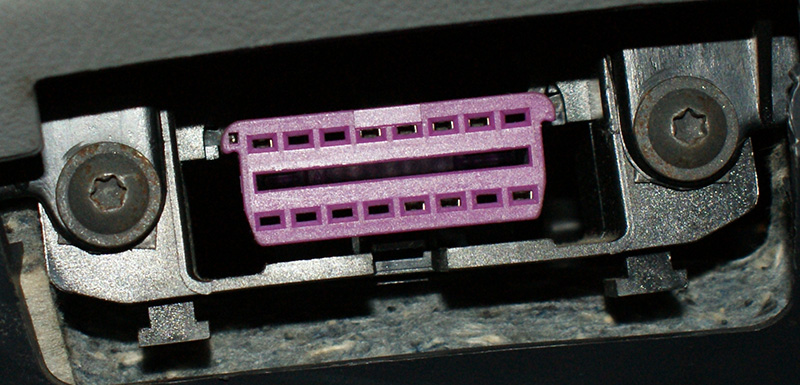
When you connect your VAG 5052 or equivalent scan tool to the vehicle, you are not always connecting to the CAN data lines. Volkswagen uses a “K†line and an “L†line as a way for scan tools to communicate with computers in its vehicles. For instance, on our 1998 Passat example with the 2.8L engine, pin #7 of the OBD II diagnostic connector is the “K†line, which connects the engine control unit, instrument cluster, airbag control unit, etc. This line is where scan tool communication happens. On later-model Volkswagen vehicles, there is an “L†line added to the diagnostic connector. This is where the scan tool initiates communication. This way the computers on the diagnostic bus know what protocol to use. Volkswagen vehicles use either J9141-1 communication protocol, or Generic OBD II. You can once again use your oscilloscope or graphing multimeter to verify that the wires have digital square waves and are not shorted to power or ground.
Due to the design of the CAN protocol, all the information is put out on the bus. Each control unit grabs the information it needs. Therefore, if the bus is up you should have communication with each control unit. If you do not have communication with a control unit or you get corrupt information, you have probably encountered a case of a bad control unit. It is possible to have one control unit putting out incorrect communication and interfering with others, but the other control units should be able to determine which one is not speaking the same computer language as they are. Check for codes in each of the systems of that CAN and you should see at least one code in each control unit highlighting the unit that is not communicating properly. Once again, do not forget that an aftermarket radio can bring down communication with your scan tool.
Communication problems should not be a difficult diagnosis. You should become familiar with how to use an oscilloscope to monitor these wires. There are tests you can perform with a Digital Multi-Meter (DMM), such as measuring the resistance of the CAN you are on to check the wiring. You can temporarily disconnect an aftermarket radio if one is installed. Finally, you can use a VAG 5052 or equivalent to talk to each control unit and figure out which one is not talking. Keep in mind that you need to properly identify the vehicle to the scan tool. Look at the 7th and 8th digits to properly identify the chassis if you are having a problem there. All of these steps should help get your started with your diagnostic process, and that should make your life a little easier.
Download PDF


0 Comments