With summer coming, you’d better be sure you’re up-to-date on Mercedes-Benz A/C service so you can keep your customers in the Temperate Zone
Mercedes-Benz owners expect their creature comforts to work properly. Nowhere is that more important than in the climate control system. Occupants require that they be kept warm in the winter and cool in the summer. Mercedes-Benz offers some of the most sophisticated climate control systems in the world, which means you’ll need some specialized knowledge for diagnosis and repair. Knowing how they work is the first step.
Thermotronic is a full-function automatic system that reads the interior and exterior temperatures and changes compressor output, heater valve and blend door position. Tempmatic is another system found on 2000 and later M-Class vehicles in the 163 chassis range. This is a combination of manual and electronic controls that work with other control units to provide air conditioning and heater management. This cooperation helps reduce wiring and saves weight. It also streamlines the diagnostic process by putting more information in the hands of the repair technician through SDS hardware and software, available for purchase from Mercedes-Benz.
Starting Off Simple
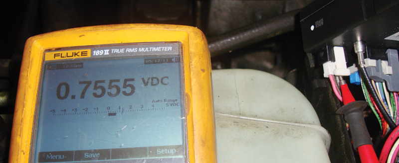
Refrigerant pressure sensor input goes to the All Activity Module, and you can measure the signal voltage at the AAM. You should have about .75V with a full system at about 90 psi of refrigerant on both high and low sides with the A/C system off.
The 163-chassis air conditioning system has undergone some improvements over the years. From its introduction in 1998 to almost 2000 (11/99), the push-button controls are only air conditioning and heater switches. They feed their inputs into a separate AAC (Automatic Air Conditioning) module mounted behind the center control panel of the instrument cluster. This module controls the blend door for temperature control of the cabin. It does not have an interior temperature sensor that provides feedback and changes the blend door position. The push-button control unit simply had a variable resistor that works in conjunction with the blend door position sensor. These two switches indicate the desired temperature to the AAC unit, which in turn positions the blend door. The module also has a sensor for evaporator temperature. If the evaporator starts to freeze, the control unit sends out a command to shut off the A/C compressor. The AAC control unit is not otherwise in direct control of the compressor.
The AAM (All Activity Module) works with the AAC module to control air conditioning and heating. It manages the coolant circulation pump and the auxiliary cooling fans, and controls the A/C compressor directly. The electrical circuits for the pump and fans are completed through relays located in the fuse and relay box under the hood. The AAM has the final say on energizing the A/C compressor. It gets A/C pressure input from the high-side line running from the compressor to the condenser by means of a three-wire sensor with a five-volt reference, signal wire, and ground. The AAM needs to see that the proper amount of refrigerant is in the system before it will activate the compressor. If the refrigerant level is too low, the AAM will not energize the compressor so it does not seize from running dry.
Getting the Compressor Started
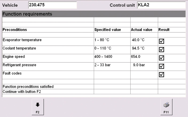
With your SDS, you can reduce your diagnostic time by evaluating the available data. Here, you can see the evaporator temperature and refrigerant pressure at a glance. You should always back up your findings with electrical testing at the component before replacement.
You should see about .75V on the signal line with a fully-charged A/C system with about 90 psi on both the high and low sides (system off). This should be enough to get the compressor started. Then, the low side should drop to under 30 psi and the high side should increase to at least 150 psi, or higher if the ambient temperature is hot. Remember, if the evaporator core temperature sensor is indicating freezing temperatures, the compressor will be shut off. If the high-side pressure becomes excessive — over 450psi — the AAM will ground the auxiliary fan relay to activate both fans. This should drop the temperature and pressure in the high side of the system. Blower motor controls are conventional switch and resistor types that regulate blower current and therefore speed.
In the 2002 model year (9/01 production date), the 163 chassis received a fully-automatic air conditioning system. Interior temperature sensors were added to the center air and foot-well ductwork. The input from these sensors contribute to the positioning of the blend door motor. The push-button panel is now the AAC control unit and takes over direct operation of the A/C compressor and the coolant circulation pump from the All Activity Module. The AAM is still in control of the auxiliary cooling fans. Rear independent temperature control was also added. A Rear Control Field Control module (RCP) sends switched inputs to the Lower Control Field Control module (LCP), which communicates on the C CAN with the AAC module. The new all-inclusive AAC module directly manages air distribution by controlling six motors. Three motors handle the defrost vent, center vent, and foot-well ducts, and the other three control the temperature blend door, fresh air/recirculation door, and rear air supply.
I’m Venting!
Each motor shares the same three wires from the AAC unit. Pin #1 is a 12V power supply, pin #3 is a ground, and pin #2 is the command signal. It is a time-based pulsed signal that sends individual messages out to each door motor even though they are all attached to the same wire. This means the signal to control each motor is sent on the same wire. There is a little more to the story than that. With a paid subscription to www.startekinfo.com, you can access factory wiring diagrams. This can be important because if you look at the 2002 model year you will see that an Extended Activity Module (EAM) is connected to the AAC control unit and the Lower Control Field Control module through a CAN. This is all referring to the 163 chassis; wholesale changes were made to the 164.
Although the AAM controls the compressor, not all compressors are the same. On the older 163 chassis, the A/C compressor has a conventional clutch to engage and disengage. This is how refrigerant pressure, and therefore temperature, is maintained. On later 163 chassis (2002 forward), a clutchless variable-displacement compressor is used. It has a rubber coupling in place of a clutch. If the compressor seizes, the fixture decouples and only the pulley spins. Compressor output is controlled by positioning a swash plate inside the compressor unit. The swash plate can be positioned from 2% to 100% swept volume. Since the compressor is always engaged at 2%, if offers almost no resistance and does not rob horsepower from the engine. A compressor control valve applies low side pressure to move the swash plate and vary the displacement, and, therefore, compressor output.Â
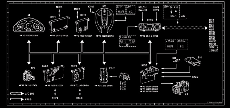
With your paid subscription to Startekinfo.com you can access specific technical information on any system. Here is a function diagram for the A/C on a 211 chassis. Notice that component B14 ambient temperature sensor goes into the front SAM. This reading is used to calculate when the compressor is turned on.
Feeling the Breeze
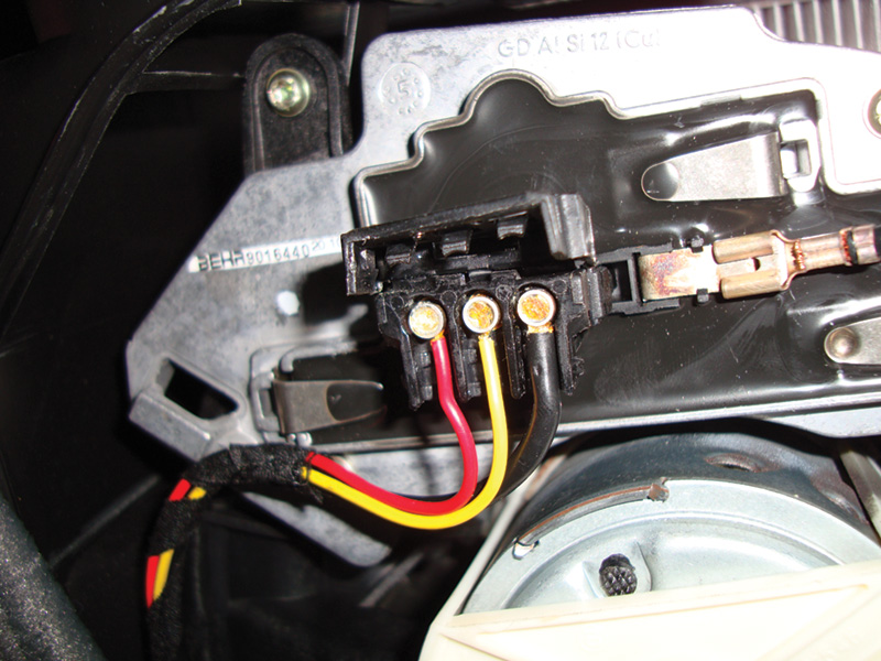
On the E-Class, the blower motor regulator has a three-pin connector as well as the single spade connector for the blower motor ground. Here, the red wire is the power supply, the yellow wire is the command signal, and the black wire is ground. Look for up to 6V from the AAC unit on the command line at full blower speed.
Not all AAC systems are created equal. The blower controls on a 210 chassis are different from those of an early 163 chassis. The 210 chassis was one of the first AAC systems to use what is sometimes called a final stage blower motor module or blower regulator to control blower speeds. The 215 and 220 chassis have a similar set up. Constant power is fed directly to the blower motor through the fuse panel by the firewall on the driver’s side of the engine compartment. The ground wire of the blower motor passes through the blower regulator, which is clipped onto the blower motor assembly. A three-wire connector applies 12V to the module, the command signal to vary the motor speed, and ground. The voltage supply is usually a larger-gauge red wire, the command signal is yellow, and the ground is black. These wire colors do not show up on the wiring diagram since they are not on the vehicle’s harness side of the connector.
The voltage command is an analog signal that comes from the AAC control unit. With the blower off, the voltage is zero. As you turn the blower speed control up, the signal from the AAC unit gradually increases from .5V to about 6V peak. If the blower module was replaced in the past, it is possible that it is being over-taxed. While it forms the ground for the blower motor, it carries all of the current the motor is drawing, which is considerable especially at high speed. Normal draw is approximately 30 amps. If you measure more than this, the motor may have a seizing bearing. Also, check to make sure the fan blades are not hitting anything. If the amperage draw is too high, you will need to replace the blower motor before you over-tax another module.
Defrost, Vent, or Footwell?
| Vehicle | 230.475 | Control unit | KLA2 |
| Control unit adaptations | |||
|
Read coding and change if necessary. |
|||
|
Normalizing of positioning motors |
|||
|
Check of adjustment range of positioning motors |
|||
|
Teaching-in of rotary potentimoeter for center nozzle and side outlets |
|||
When dealing with a door mode control problem, you must understand a few things. There is AAC and C-AAC. The AAC system automatically adjusts the air conditioning and blend door operations to match the temperature selected. The C-AAC system can do the same thing, but there are temperature sensors in the ductwork that can change the position of the door to maintain the selected temperature. Mercedes-Benz uses a few different systems to control the position of the motors. The first is the three-wire system mentioned earlier. A common power supply, signal command, and ground are connected to every motor. The signal wire carries the square wave that commands the position of each motor. This can be found on the 163, 203, 211, and 230 chassis. The 215 and 220 chassis uses a slightly more sophisticated system.
The flagship sedan and coupe use a C-AAC to manage the overall climate control system. A separate control unit handles the stepper motors directly by providing an individual power supply to each motor. Just like a normal stepper motor that might be used to control idle speed, EGR flow, etc., four wires are pulsed to ground to change position. The stepper motor control unit receives its directions from the C-AAC control unit. The signals are sent over the dedicated AAC CAN, also known as the KLA CAN. Other sophisticated components communicate over this CAN, such as the center vent control unit, sun load sensor, and the multi-function sensor. The multi-function sensor reads various data from the environment. Aside from reading outside temperature, it can read humidity, CO, and NOx. This provides information for an optional air filtration system. Outside air can be directed through two activated charcoal filters that can catch pollutants.
Tools in the Arsenal
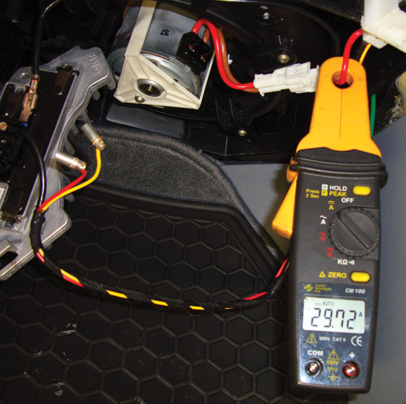
A “good†blower motor will draw approximately 30 amps when supplied battery voltage and direct ground. You should check the amp draw if you need to replace the blower regulator to verify that you will not have a repeat failure.
No matter which system you are working on, you are going to need an SDS to finish the job. Each AAC control unit has multiple sensor inputs and communicates with other control units to operate the A/C system. You can access all of the data for each of these units with your SDS, which is available for purchase from Mercedes-Benz USA. You can find this information on www.startekinfo.com/Star Diagnosis/Aftermarket. With the new Xentry software, you can either go directly into the AAC control unit or evaluate the data in the AAC unit directly. This will give you data and control from other control units that work with the AAC. This data can be critical to A/C operation. For instance, the outside temperature sensor signal is usually sent to the front or driver’s side SAM. This information is used by the AAC unit to control A/C operation.
If the sensor signal indicates a very low temperature from a broken or missing sensor, the circuit would be open. Like any typical NTC (Negative Temperature Coefficient) sensor, the higher the resistance through the sensor the higher the signal voltage. An open circuit would indicate freezing temperatures. In this case, the A/C compressor would not be commanded on since the electronics believe the outside air is cold. The same situation could be said for the evaporator temperature sensor or interior temperature sensor. If both sensor inputs indicate it’s too cold, the compressor will not come on. Both of these inputs come directly into the AAC control unit. Only the outside air temperature sensor is sent to the SAM, so you may not see the data in the AAC control unit unless you look at the overall A/C system with your Xentry software. Other functions are required to bring an A/C system online after service.
The SDS to the Rescue
After evacuating the system and then recharging it with the correct amount of refrigerant (see the label in the engine compartment), the compressor may still not come on. If a diagnostic trouble code blocks A/C operation, you will have to clear the code before the compressor will be commanded on. This should be done after the A/C system is serviced. After servicing a mode door control motor, you will also have to normalize the door positions. There is a procedure in the SDS for this. When you perform this function the AAC control unit or the stepper motor control unit commands each motor to the end stops and remembers the positions of each. The automatic temperature and mode door motors can make adjustments to meet the changing conditions. Automatic functions may work incorrectly if this step is not followed.
There are other opportunities for service on Mercedes-Benz A/C systems. Statically-charged particle filters are installed on most models and charcoal activated filters are available for high-end models. Your Mercedes-Benz dealer’s parts department can supply you with OEM quality filters, which are better than aftermarket replacements. Mercedes-Benz has a detailed catalog of remanufactured A/C components such as A/C compressors, so your customers can have OEM quality replacement parts. Diagnosing the problem accurately and installing quality parts is why your customers come to you for their service work. Let Mercedes-Benz stand behind your work with warrantied components and your customers should have no problem keeping their cool.Â


0 Comments