Modern automatic transmission failure diagnosis can be daunting. Use these easy methods for testing the suspected component or system, research the specific service information – and apply a little logic – and you’ll get the job done faster and more accurately.
Automatic transmissions existed long before advanced electronic systems were available to control them. What was once a virtually self-contained system has now spread out. While it’s still called an “automatic†transmission, it has actually become more of a controlled transmission. Without a lot of external help, modern automatic transmissions are just a single-speed gear reduction.
First, the information necessary to make gear selection choices is now made based mostly on components outside of the transmission housing. The information the throttle pressure cable once provided is now furnished by the ECM, based on input from sensors such as the TPS. Vehicle speed is now also measured via sensors and relayed to the TCM through the ECM. Finally, the “clockwork†that once opened and closed valves and directly controlled shifting has been replaced with externally-controlled solenoid valves.
The decision-making is now done outside the transmission case as well. Mechanical hydraulic systems are not capable of the same level of “intelligent†thinking as an electronic control module, and intelligent shifting choices are necessary to increase efficiency, performance, and drivability. Shift timing and clutch application can now be perfectly matched to driving conditions. The torque converter clutch can be locked in any gear or even partially locked with duty cycle control. The control unit is even able to recognize driving situations, such as a grade, and provide engine braking or prevent overdrive hunting as appropriate.
“Programming†a pure mechanical hydraulic system for this level of control would be nearly impossible, and, even if it were, the added weight would be unacceptable.
Thus, the modern transmission has become mostly output. There are a few sensors, and there is still some direct mechanical hydraulic control, but most of the transmission’s function is actuation: to put commands into action, not to evaluate or make decisions. Changing gear ratio requires input, logic, and output. Only one third of this system lives within the transmission housing. Therefore, the odds of accurate diagnosis-by-test-drive or replace-based-on-symptom are lower than ever before. This is why thorough transmission diagnosis is critical, even if your shop usually replaces rather than repairs.
Easy as 1- 2 – 3
The fundamentals of transmission diagnosis are much the same as the fundamentals of diagnosing any computer-controlled system. Just answer the following questions:
- How was the system designed to work? Computer control is all about logic – “if this, then that.†Find out what the transmission should be doing, then see if it is doing it.
- What are the relevant sensor inputs, and do they match actual conditions? If not, why?
- What are the outputs, and do the output commands match the actual output. If not, why?
Research is the first step, but in order to research efficiently, you must have a direction to pursue; an idea of where to focus the enquiry. So, without spending too much time, carefully read the symptom description on the repair order, test drive the car, and check for trouble codes. However, it’s important not to get sucked into trying to perform diagnosis before understanding how the system should work, so as soon as you’ve found a direction, leave the car and head for your laptop.
There are several very useful areas in the service manual. If you have a trouble code (DTC) to work with, the section that covers On Board Diagnosis Logic is extremely useful. It’s possible to “get inside the mind†of the TCM and know what it’s going to do (or at least what it should do). If you know how the TCM is testing the system, and how it will interpret the results, you’ll be able to set up your own testing; drive under appropriate conditions, monitor the sensors the TCM uses to test, and apply the logic the TCM applies. A little research, observation, logic, some simple math and you’ll be in a position to evaluate what’s happening, just like the TCM, but with a lot more processing power and flexibility of thought.
Divide and Conquer
“Divide and conquer†is a term adapted to a network diagnostic technique that works wonderfully for almost any diagnostic situation. In essence, the idea is to test the system from as close to the middle as possible, decide which side has the problem, then divide that side in the middle as well, decide which side has the problem, and continue to divide and decide until the problem is isolated.
The “center†of the system is the TCM. Inputs and outputs are all on display from the comfort of the driver’s seat using the CONSULT III PLUS. The CONSULT III PLUS allows the technician to view the system from the middle. You’ll be able to see what the TCM sees and how it responds; the relevant input signals and the output commands.
Often, the “Service Engine Soon†(MIL) and “AT Check†light will come on when there is a problem with shifting. Sometimes this will happen before the driver even notices any other symptoms. When a DTC is present, it’s almost always best to start with trouble code diagnosis before trying to diagnose by symptom, but in the end, every situation is different, so do what makes the most sense based on the situation.
Diagnostic Trouble Code Diagnosis
Start by looking at Freeze Frame Data (FFD). Perhaps “looking at†is not a good way to say it; FFD should really be “examined,†or “analyzed.†Look carefully at all of the PIDs. Are they related to the DTC detection logic contained within the FFD? If so, can you see why the code set? Are any of the PIDs obviously impossible? The TCM uses rational comparison of inputs, and so can you. Also, note all of the conditions related to the conditions when the code set so that you can duplicate them on a test drive for diagnostic and repair confirmation purposes.
When a transmission-related DTC is found, or you suspect a condition exists that might cause a code with a little more duration, try the DTC WORK SUPPORT feature in CONSULT III PLUS. It’s a very handy tool to determine if a problem is currently occurring. DTC WORK SUPPORT for AT codes can be found by selecting AT>DTC WORK SUPPORT, then choosing the appropriate test for the DTC or symptoms. In order to run the DTC WORK SUPPORT test, the driving conditions must match the test criteria. In other words, if you’re testing for 1st gear function, you’ll need to drive the car under conditions that allow the TCM to test the function of 1st gear. Instructions for doing this can be easily found in the service manual. Still using the 1st gear function as an example, look under the diagnosis section for P0731 (1st gear function) and use the Diagnostic Trouble Code Confirmation Procedure found there.
The guided testing of DTC WORK SUPPORT is not the only method of diagnosis, albeit a convenient one. When all else fails, it’s possible to use logic to diagnose the problem. However, in order for logic to work, you must have true statements to work with, and the best place to find the true statements is in the service manual.
It’s important to note that the presence of a DTC may alter the logic of the transmission. For instance, if the transmission is slipping badly in 1st gear and a P0731 is set, the TCM could decide not to use 1st gear and start off in 2nd. If you want to confirm the original symptom on a test drive, you may need to clear any DTCs first.
Inputs
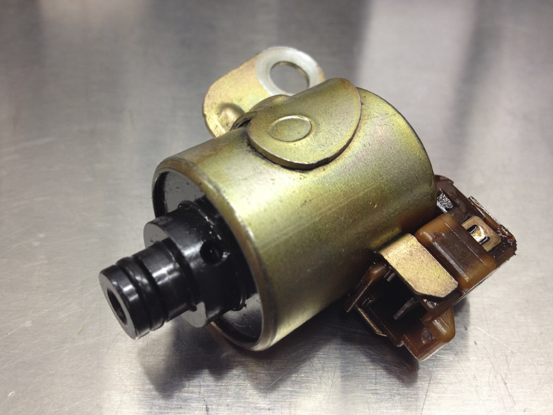
Solenoids can fail electrically (an open or short in the windings), or become stuck. Sticking is usually caused by fluid contamination. Fluid should be replaced if a stuck solenoid is found. However, if a transmission is worn and continues to dump debris into the fluid, a replacement solenoid may only be a short-term solution.
It makes sense to start by looking at the inputs, as output is based on it. Let’s say a vehicle is in the shop with the complaint of no overdrive. After checking the system description you know that the overdrive cancel button must not be pressed, the transmission fluid must be up to normal operating temperature, and the vehicle speed and load conditions must be suitable for overdrive gearing.
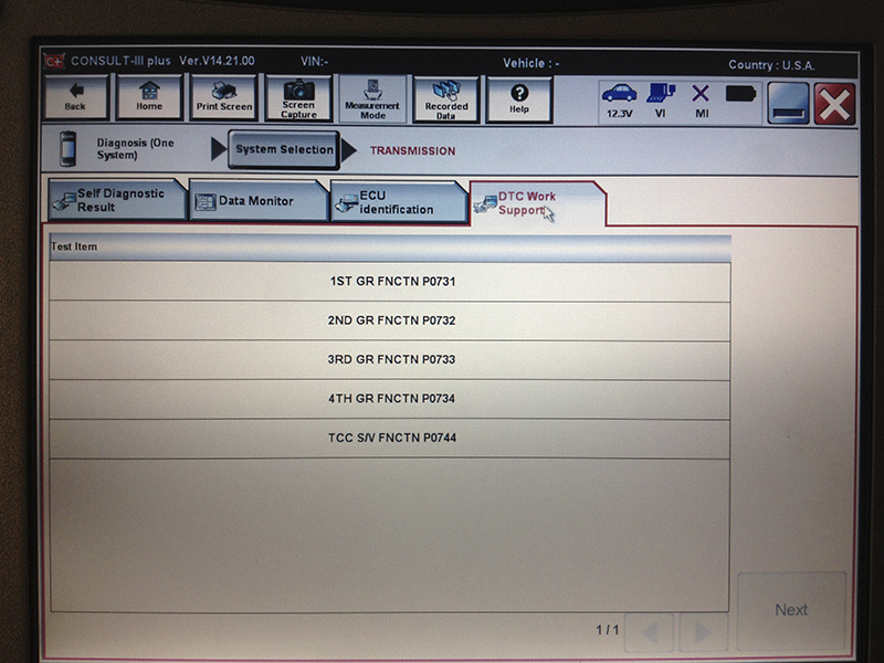
The DTC WORK SUPPORT feature on the CONSULT III PLUS can determine if a problem is currently occurring.
What inputs should be checked? Probably the Throttle Position Sensor (TPS), Transmission Fluid Temperature Sensor (AT Temp), the O/D lockout switch (3rd gear switch), and vehicle speed inputs like the Vehicle Speed Sensor (VSS) and Output Shaft Speed Sensor (AT REV). These are the inputs the TCM will examine to make the decision. In order to decide whether the problem is with input, logic, or control, you should monitor relevant input, research the logic descriptions, and verify desired output. If the 3rd gear switch PID is ON, then the logic and output are as designed, so focus on why the 3rd gear PID switch is on.
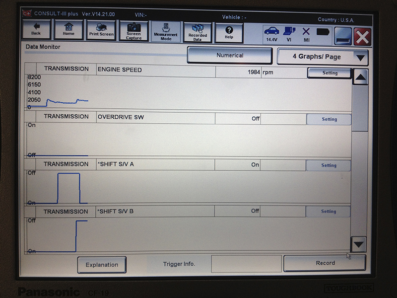
Test driving the car using the DTC WORK SUPPORT will allow the CONSULT III PLUS to check each transmission function.
Logic
Once input conditions are met for a particular output, the next question is: Is the TCM output in agreement with the description in the service manual? It’s rare to see a logic failure, so if you think you’ve found one, suspect a manual error. Compare it against an identical vehicle before ordering a TCM. However, there are often updates available to improve transmission performance and longevity, so always check for TSBs.
Output
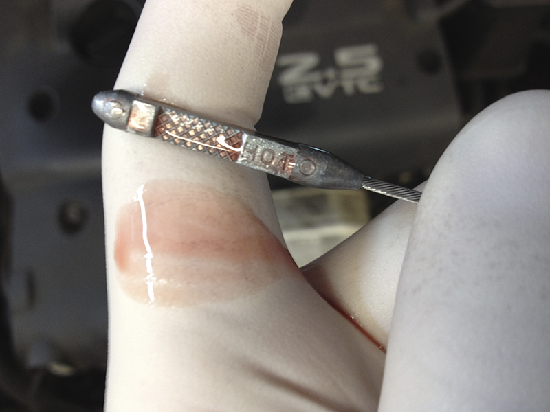
Transmission fluid should be translucent and free of floating debris. Most fluid is dyed red, but some fluids, like NS2, may have a different tint. Some types of fluid have a sweet odor when in good condition, but others can smell a little “sharp” even when new. Don’t rely on odor as a gauge of condition unless you are familiar with what “normal” smells like.
The output PIDs indicate what the transmission “thinks†it’s doing. If the transmission is not doing as commanded, it’s time to find out why. This can be broken into five questions:
- Is the solenoid output signal leaving the TCM?
- Is the solenoid output signal reaching the transmission?
- Is the solenoid operative?
- Does the output have the support it requires (fluid pressure)?
- Is the actuator the solenoid controls receiving the desired output?

Transmission fluid becomes opaque and brown as it degrades. An acrid burnt odor and floating bits of clutch, bushing, and steel shavings are signs of trouble.
As stated earlier, start in the middle; is the solenoid operative? There’s usually no need to remove the suspect solenoid from the transmission for resistance testing or power testing. If the solenoid can be heard clicking, it’s likely the TCM output, wires, and solenoid are all okay. If there is an active test available for the solenoid, use it to cycle the solenoid. If not, it may be possible to operate the solenoid with the KOEO in gear (depending on which solenoid and which car). Finally, the solenoid can be activated using the instructions in the manual while listening for clicking. A fuel injector balance tester is a handy tool for this method.
Mechanical and Hydraulic Problems
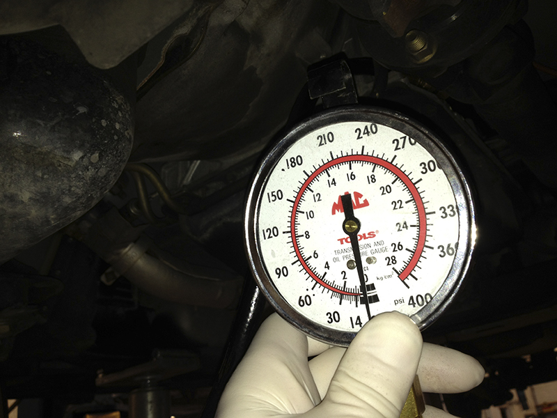
Fluid pressure does most of the work in the transmission. Use a pressure gauge to find out whether fluid pressure is adequate and if it’s being directed properly.
Once problems with transmission control systems and solenoids have been examined, there are still plenty of things that can go wrong inside the transmission case. The most common causes of failure can be put into three categories:
- Mechanical wear causing noise/vibration. The debris from the failing parts may also jam solenoid valves.
- Clutch wear causing excessive clutch pack clearance and slipping. This too may cause solenoid valves to get stuck.
- Inadequate fluid pressure caused by either poor pump output or internal leaks.
Mechanical wear is best diagnosed by examining the fluid and the inside of the transmission pan. Clutch wear is usually diagnosed through a combination of test driving and fluid/pan examination. Fluid pressure issues should be diagnosed using a pressure gauge and the tests outlined in the service manual.



0 Comments