Volkswagen has been working hard to make its automatic transmissions more efficient.1 They shift faster and more smoothly than ever before, and help improve mpg. Let’s see what we can do to keep it that way.
Worldwide, Volkswagen sells some of the highest numbers of manual transmission-equipped vehicles, but in the U.S. automatic transmissions outsell sticks. Since manuals have a zero-slip mechanical clutch, they are inherently more fuel efficient1 than automatics with their torque converters. Torque converters by their nature are not as efficient as the direct-drive mechanical clutch of a manual gearbox. Volkswagen’s automatics are, however, getting more and more efficient.1
In the early- to mid-’90s, Volkswagen produced several different variations on the automatic transmission theme. The 01M and 01P were the first with electronic controls. They had evolved away from mechanical valve bodies and used computer-controlled solenoids to manage shift points and torque converter lock-up. In 1998, the Passat appeared with the ZF-built 01V, and it was one of the first to use an electro-hydraulic valve body. In 2002 the Golf and Jetta came with the 09A transmission built by JATCO in Japan, which also featured computer-controlled shifting. In later years, the five-speed 09A/09B transmissions were introduced along with a six-speed gearbox designated as the 09D, 09G and 09M.
The Basics Evolve
This means there is a lot of opportunity for servicing these drivetrains in our future. Most Volkswagen transmissions use a synthetic or synthetic-blend fluid, which is considered “fill for life,†but in the event you have to repair one you will have to drain and refill the system. You should know that when you remove the pan and empty the system, you are only removing approximately 1/3 of the volume of old fluid.
In order to properly service these units and diagnose problems, you need to know the particulars, especially when it comes to the Transmission Control Module (TCM) function and operation. Like any other computer-controlled system, there are sensors that tell the TCM the conditions the vehicle is under. These sensors are directly wired to the TCM, and since that module works within a CAN system, outside control units can have an effect on shifting. You need to know what affects these inputs, direct and indirect, can have on shifting if you are going to address your customers’ complaints.
The next step in any transmission diagnostic procedure is to check the fluid level. On the surface, this seems simple, but there is more involved than just removing a dipstick. On the 01V transmission manufactured by ZF, the rear differential is filled with separate gear oil. On the JATCO unit, the fluid used in the transmission is the same as that used in the differential. This means that a leak in the differential will lower the level in the transmission.
By ’95, most Volkswagen transmissions no longer had a dipstick. Instead, there is a stand pipe inside the transmission pan that is blocked with a plug. Remove it to see if fluid comes out. If it does, the level is correct. Keep in mind, though, that this has to be under certain conditions. Number One is that the engine has to be running so that the pump is drawing and circulating fluid throughout. Also, you should connect a scan tool and interrogate the TCM to monitor the fluid temperature. It should be at approximately 85 deg. F. (30 deg. C.). You can usually get within that range by letting a cold vehicle idle for three minutes with a starting temperature of 60 deg. F.
Plugging the Leak
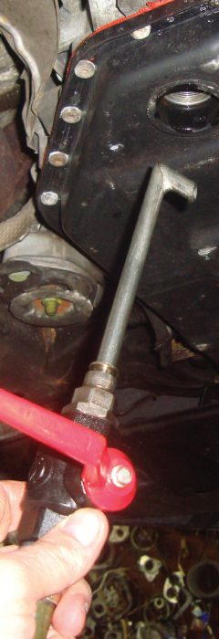
When looking for leaks, Volkswagen does not recommend that you add a phosphorus-type leak detector to the fluid for use with a black light because you cannot predict how these or any other additives will affect the components. Instead, Volkswagen recommends that you sprinkle or spray a thin layer of talc power or silver spray paint around the potential leak source. Go on a road test, then inspect the trail left as the leaking fluid washes away the talc or paint. After looking at the level, consider the fluid condition. Dark or discolored fluid indicates that it is “burnt.†Slipping clutches and over-heated fluid, possibly from a clogged cooler, indicate severe transmission damage. Some service facilities may advertise that a fluid exchange may alleviate the problem, but it would be a temporary fix. A fluid exchange may remove deposits from sticking valve bodies, but worn clutch material cannot be replaced with a transmission transfusion. If the fluid level is within its operating range, the problem may be deeper. The next step should be to see if the TCM has set any Diagnostic Trouble Codes (DTCs). The TCM has sophisticated electronics that are capable of picking up problems in the system.
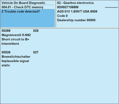
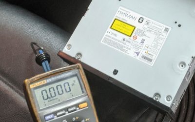
The TCM is in control of how and when the transmission shifts. It calculates this from a variety of direct sensor inputs and further inputs that come in on the powertrain CAN system. The TCM then manipulates output controls and also sends information out on the CAN for the other controls units to react to accordingly. Let’s look at the inputs the TCM looks at to make these “shifty†decisions. One major input to the TCM is the transmission range switch. This switch indicates the gear position the driver has selected. Previous to 1998, the transmission range switch was a typical multi-switch unit where one contact would indicate each gear position. After ’98, a Hall-effect switch was used. Here, four contacts toggle between ground and a 5V reference. Since there are four switches that can only indicate 0V or 5V, each gear position has a different combination of the four switches. For example, if switches #1 through #4 read 0V,0V, 5V, 0V, this indicates the Park position. In reverse, the combination would change to 0V, 5V, 0V. This type of switch can be checked with a Digital Multi-Meter (DMM), but it is very difficult and time-consuming to measure each switch voltage in each gear position. With a VAS 5052, you can read this information in data block and quickly run through the gears to check the transmission range switch.
Reading the Speeds
When it comes to transmission shifting, engine rpm and vehicle speed are critical inputs to the TCM. Therefore, there are three sensors that are wired directly into TCM and one that comes in on the CAN. There are a few variations with Volkswagen transmissions, so there may be a different combinations of input speed sensors. This is one of the reasons it is critical to know the exact make and model of transmission with which you are dealing. Most Volkswagen transmissions have one sensor devoted to mainshaft input speed, a second sensor for output shaft speed, and an overall vehicle speed sensor. An input shaft speed sensor can be calculated off of the engine speed coming in on the CAN. The output shaft speed sensor can also be used to calculate the overall vehicle speed. For the most part, you have individual sensors directly wired to the TCM. These are typically pulse generators that put out an AC voltage signal. The TCM calculates the shaft speed off the frequency reading, although the AC voltage will increase with speed. The difference between the input and output shaft speed sensors can determine if the gear ratio is off, which an indication of slipping clutches or sticking solenoids.
There are other important inputs to the TCM that have an effect on shifting. Transmission fluid viscosity is significant to shift quality, and the fluid temperature sensor reports to the TCM. The hotter the fluid, the thinner it is. If an engine were to run hotter than normal under hard acceleration, or up a long hill, the fluid can get hot enough to affect shifting.
One of the more obvious inputs is the kick-down switch. Before electronic control, kick-down was managed by a Bowden cable, which is a mechanical linkage to the from the throttle. Now, a switch is attached to the accelerator pedal. Near the end of pedal travel, the switch changes state and indicates to the TCM that the driver has applied full throttle. This causes the TCM to “kick-down†to the next lower gear. As a result, engine rpm increases and the vehicle accelerates faster. When you evaluate the wiring diagram for the particular transmission you’re working on, you may notice a brake switch input. It can be directly wired to the TCM as well as to the ABS, ASR, or ESC control unit. Obviously, under braking to a stop, the transmission will need to down-shift.
Coding The TCM
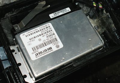
Since shifting is now computer-controlled, variations in coding can change it. For example, on the 01M transmission in the 1998 Passat you can code the TCM with the Dynamic Shift Point (DSP) active or inactive by changing the fourth number in the coding string. If you enter “0,†DSP will be active. This means the control unit will learn how the car is being driven and change shift points to match the driving style. If the driver accelerates rapidly, the TCM will call for later shifts for better acceleration. If the DSP is inactive (coding number “1â€), the TCM will shift at fixed points by vehicle speed. You can also code the TCM into an economy or sport mode by changing the fifth digit in the string. If you put in a “1†as the fifth digit, you will command economy mode, in which the TCM will shift earlier with relatively lower engine rpm for better fuel economy. If you put in the number “2†as the fifth digit, you will command sport mode, in which the TCM will shift at higher rpm for more power. If you have selected to have DSP active, you will not be able to choose either of these modes and you will need to enter the fifth digit as “0â€. So, a coding number of “00000†means DSP is active. If you code the TCM for economy, you will enter “00011.â€. Sport mode can be selected by coding the control unit with the number “00012.â€
The TCM controls shift points by operating solenoids throughout acceleration and deceleration. These solenoids are divided into two categories: shift solenoids and pressure-control solenoids. The former are simple on/off units that either open a passage in the valve body for fluid to flow, or close it. Different combinations will produce different gear positions. Pressure control solenoids are usually duty-cycle controlled and vary the amount of pressure applied to a clutch. This allows for smoother shifts that are less noticeable to the driver. With a paid subscription to www.vw.erwin.com, you can access clutch and brake apply charts. These let you know which solenoids have an effect on the shift point you may be having a problem with. You can also use solenoid apply charts to let you know which solenoids are being activated and which are not. You can evaluate all of this data with your VAS 5052. In data, you can look at the amperage control of the output solenoids, which are normally open. Therefore, a lower current reading means the solenoids are open, and a higher amperage reading means the solenoids are being commanded closed.
Solenoid Control
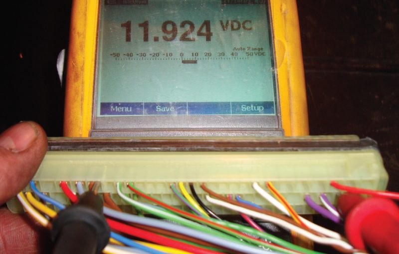
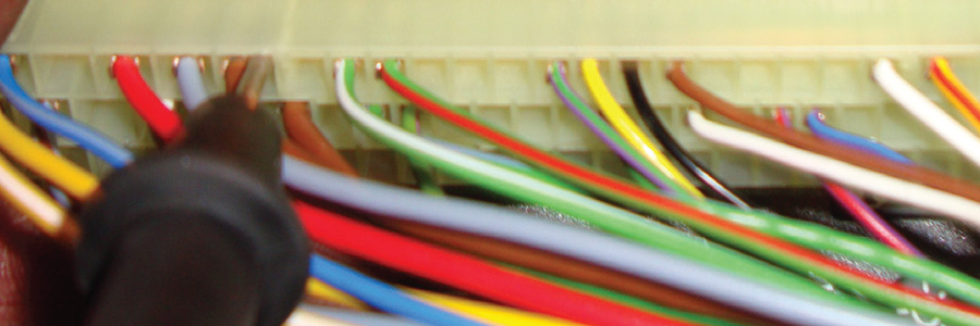
The TCM supplies the power and ground control of the shift- and pressure-control solenoids. If any of these or the wiring were to fail, the transmission would default to a single gear, usually third. This allows continued driving to a shop for repair. While on your road test, check the engine rpm to verify that the transmission is shifting. If it isn’t, you should have DTCs indicating why the TCM is in “limp-home†mode. For instance, if you pull a code 17086 on a 01V transmission (TCM electrical malfunction, or defective control unit) the problem may not be in the control unit. Evaluate measuring block 003 in the TCM and look at field #4. This PID represents the voltage supply to the solenoids. You should read battery voltage in gear with the engine running. If you do not, you need to access the TCM under the passenger side floor carpeting and check terminals 52 and 53 for battery voltage. One terminal is the supply voltage for the shift solenoids, and the other wire brings the supply voltage to the pressure control solenoids. The TCM monitors the supply voltage coming back from each solenoid to determine if there is a wiring harness problem.
Having a basic understanding of how Volkswagen automatic transmissions work will help in addressing your customers’ concerns. The process starts by properly identifying the model you are working on, followed by checking basics like fluid level. Finally, check for any DTCs and evaluate scan data pertinent to the problem. Back up your evaluation with visual examination and electrical testing of the circuits in question, and you should come to the quick and accurate diagnosis that your customers expect from you. With the help and support of your Volkswagen parts supplier, you should be able to provide a complete repair the first time.
Download PDF

0 Comments