Much of your electrical and electronic testing will be meaningless if you don’t.

Batteries have evolved a great deal since this old German specimen from Robert Bosch was state-of-the-art. Note that the plate separators are made of balsa wood.
It was many years ago when we first heard a veteran automotive service technician use the term “baselining†in regard to diagnosis. He was referring to the eminently sensible practice of making sure all the basics of vehicular motivation are in satisfactory operating condition before embarking on high-tech troubleshooting of a driveability or emissions problem. That meant giving everything involved a quick visual exam for obvious stuff like broken or disconnected wires, a loose or contaminated belt, leaky vacuum lines, a perforated duct downstream of the MAF, battery cable and clamp issues, etc. To take this further, you might pull the plugs for a compression test, or at least see what your vacuum and fuel pressure gauges tell you, then put your DMM across the battery to look for 12V+ with the engine off, and maybe 14V with it running. A few voltage-drop tests of the starting and charging systems wouldn’t hurt, either.Â
Today, lots techs would disagree with all this traditional preparation, preferring instead to plug in a scan tool as a speedy first step. We see the point in this hurried modern world, but ignoring electrical baselining can send you off in a false troubleshooting direction, thus costing you way more time than a few simple tests would’ve taken.
Battchem

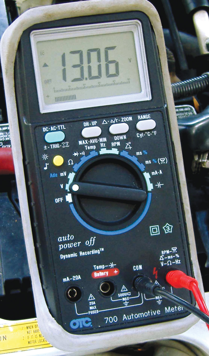
Except on the latest models with the “energy management†charging system, if you’re seeing a reading this low across the battery with the engine running, you’ve found trouble.
The prime mover of any automobile is, of course, the battery. Alas, most of us haven’t retained our high-school chemistry, so perhaps a recap of lead-acid battery operation is in order, to which we’ll add news on recent developments. The basic principle is that if two dissimilar metals are placed in an electrolyte that can attack them, voltage potential is created. Electrons will flow if a connection is made between the metals, and that’s what electricity is.
In a wet cell, the metals are sponge lead (Pb) and lead peroxide (PbO2), and the electrolyte is dilute sulfuric acid (H2SO4). The reaction begins as sulfate (SO4) breaks away from the acid and unites with the lead of both the positive and negative plates to form lead sulfate (PbSO4). The oxygen (O2) is thereby liberated from the lead peroxide and joins with the hydrogen (H2  what’s left over after the sulfate left the acid) to produce ordinary water (H2O), which dilutes the electrolyte. Eventually, both the plates turn into lead sulfate, the electrolyte becomes very weak, and current stops flowing.
But reversibility is the wet cell’s most important characteristic. When an outside power source pushes electrons through the cell in the opposite direction to that of discharge, sulfate separates from both plates to rejoin the hydrogen in the water, forming a new batch of sulfuric acid. The oxygen goes back to the positive plate to recreate lead peroxide, and the electrical potential is restored. If charging continues after all the sulfate has gone into the electrolyte, the water starts to decompose, releasing free hydrogen and oxygen, an explosive couple.
The traditional automotive battery has plates made of a combination of lead and antimony impregnated with the metals involved in the reaction. Numerous plates of each metal are interlaced within one cell, but whether two or a dozen are used each cell produces a “pressure†of 2.1V. Six cells are connected in series to give the 12.6V almost all cars have needed since the 1950s.
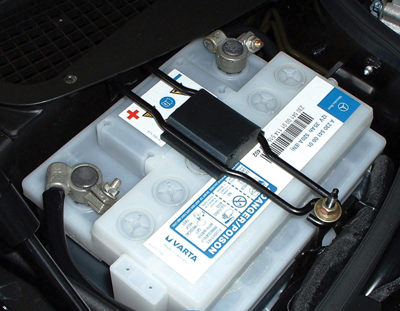
Most modern Mercedes-Benz vehicles use an Absorbed Glass Mat (AGM) battery. The glass “fleece†absorbs the sulfuric acid while still allowing it to circulate for the chemical activity necessary. The advantages of AGM are increased service life, ability to withstand a deep discharge, and they won’t spill sulfuric acid on the passengers in the event of a rollover. Since modern designs have moved the battery into the trunk and even the cabin, it has become critical to replace the battery with the proper non-spillable type.
No more than 20

Mercedes-Benz has approved this sophisticated battery tester from Midtronics, which produces
accurate results in
no time and without applying a potentially-damaging load.
By their nature, AGMs are susceptible to damage by overcharging. So, a 20A max automatic charger that carries Part Number 110-9420 is available from your local Mercedes-Benz dealer.
AGM or not, the diagnosis of batteries has evolved beyond hydrometers and traditional VATs. Mercedes-Benz recommends the use of the Midtronics 165-EXP-717 no-load battery tester, which gives you a definitive answer almost instantly, and is available from your local M-B dealer’s parts department. You can still use your old VAT, but since it’s hard to get a sample from an AGM for hydrometer testing, it’s hard to feel confident in your findings.
Whenever your testing says the battery is beyond help, a Genuine Mercedes-Benz replacement is the best choice. Not only will it have been manufactured by companies such as Varta, which has been in business for over a century, but the warrantee is unimpeachable, and there will be no problem with installation.
Charge!

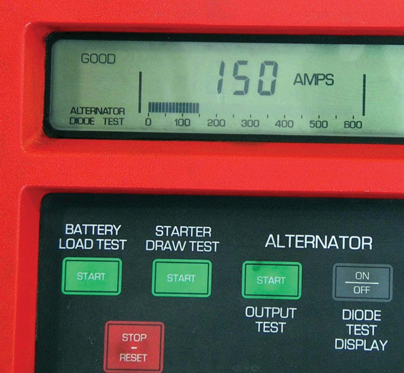
That doesn’t mean there’s no place for your traditional VAT. The carbon-pile load can still give you useful information.
A modern charging system is composed of an alternating current generator with a rotor comprising an electromagnetic coil wrapped around an iron core and enclosed in two six claw pole pieces. It receives regulated voltage through a pair of brushes that bear on slip rings, and this causes it to produce a magnetic field. An engine driven belt spins the rotor inside the stator (three coils wrapped on a ring), and this is where the current is induced.
But this set up produces AC, and automobiles need DC. So, the current must be rectified (that is, converted from AC to DC), and this is accomplished by six diodes, a negative and a positive for each stator coil, and three exciter diodes that supply the field with current once the engine is running. When the ignition is first switched on, field current comes from the battery through the charge indicator lamp.
Symptoms of charging system illness include a low or dead battery, or one that’s cooked from overcharging, alternator noise, dim bulbs, and a charge indicator light that shines at the wrong time. Whenever you encounter a vehicle that exhibits any such failing, it only makes sense to check the simplest things first.
The belt, for instance. Suspect slippage if the trouble only occurs when it’s raining, or at high speeds. Pop the hood and give the belt a yank and a look.
Next, check for corroded battery terminals, broken wires, and big time shorts (we’ve seen several alternators in a row burn out on the same car because a missing grommet or a gap in insulation made them work themselves to death).
If you suspect that a short circuit or other draw is draining the battery, testing is not as simple as it was in the old days before CAN. Back then, you could just make sure all the accessories were off, including the courtesy lights, remove the negative cable from the battery, and connect a test light between the battery post and the cable clamp. If the light glowed, you’d remove fuses until it went out, which effectively isolated the leaky or hungry circuit.

A genuine OEM replacement battery, such as this one from one of the oldest and most respected battery manufacturers in the world, will last far longer than what you’d get elsewhere. Note the Mercedes-Benz cable clamps, which are much more robust than those from other car makers.
Today, of course, there are different things to consider. First, never disconnect a battery unless you’ve got the radio security code handy. Second, it’s best to use your DMM (Digital Multi-Meter) switched to mA to quantify the drain (it would have to be pretty bad to blow the meter’s fuse). Connect the DMM before removing the clamp from the post so that the system is never completely deprived of voltage. A parasitic draw of 10 to 50 mA is generally considered the normal amount needed to maintain the electronic memories.
Then there are the CANs (Controller Area Networks) to keep in mind. When the ignition key is switched off, either the EIS (Electronic Ignition Switch) or the CGM (Central Gateway Module) senses this and sends out signals to put the control modules on the CANs into a “sleep†or power-down mode. This can take a matter of minutes, so if you were to measure draw immediately after turning off the key, you’d see way more than the “normal†reading, and perhaps be thrown onto a fallacious diagnostic path, hunting for problems that don’t really exist.
Remember, the traditional procedure of unplugging fuses to locate the draw may be augmented by unplugging control units from the CAN for the same purpose.
By the way, when the control units go to sleep, the CAN voltages change. CAN H drops to .025V and CAN L increases to 11V. The voltage may seem high, but the current draw is very low.Â
Where did the pressure go?

A modern AC generator/alternator should last a long, long time, but typical failures are blown diodes and worn-out brushes.
The concept behind voltage drop testing is somewhat subtle, so lots of people don’t really understand it. Any load in a circuit, whether intentional (an accessory) or unintentional (a bad connection), will use up voltage, and a measurement taken across that load reflects the amount. Where you can get confused is that you’re in parallel along some segment of a circuit, and since you’re used to looking for voltage between the feed side and ground, it seems sort of strange that there’d be a reading in parallel. The thing to learn is that the load absorbs some voltage, so there’ll be a difference between what’s available on one side and the other. What you’re reading is that difference.
Although resistance is stated in ohms, for most automotive work the best way to test for high resistance is with voltage, specifically “voltage drop.â€Â This is measured “across†each component, with the positive lead of your voltmeter on one connection of the component or length of wire, and the negative lead on the other. Make sure the negative lead is on the side that goes to ground. As we said, any load in a circuit, good (an accessory or wiring), or bad (poor connection), absorbs voltage. The measurement is the amount of voltage absorbed.
This also bears repeating: Where you can get confused is that your meter connections are in parallel to what you are measuring. Current is flowing through the component and through your meter at the same time. A high voltage drop reading means whatever you are measuring is absorbing a lot of voltage, leaving little for the rest of the circuit.
Switches, wiring, and other connections should have very little voltage drop because they’re not supposed to absorb any voltage to speak of. If the reading is high, there’s too much resistance. Devices, such as a light bulb, blower motor, etc., should absorb voltage. If there is only one device in a 12V circuit, the device should absorb all 12V, except for the small amount that may be lost in the wiring. If there are two devices, both the same size, each will absorb six volts.
A common question at this point is, “Why not simply switch my meter to ohms and measure resistance directly?â€Â The best way to answer that is with a simple example of static vs. dynamic states. Suppose you have a #6 multi-strand wire between the battery negative post and a ground on the engine block, and the connections are perfectly clean. If you open the insulation and snip all but one tiny strand, then measure ohms, you’ll see no resistance — that single strand of copper will pass plenty of current to get the meter to read.
But what happens when you engage the dynamic state by trying to crank the engine? Well, there’s no way that little electrical path will be able to pass hundreds of amps, and it’ll burn itself open resulting in infinite resistance. It’s no-load vs. load, what happens when a circuit is asked to actually operate. And the same applies even to small wires and connections.
DMM and DSO
So, voltage drop testing is the only real-world way of looking for excessive resistance. As far as the equipment needed, the basic requirement is obviously the ability to measure small amounts of voltage. Before the advent of digital electronic devices, a low-reading analog voltmeter was all we had. Now, of course, the DMM is required. Its high input impedance (typically 10 megohms) protects fragile computer circuits and eliminates noise. Also, many versions with what’s variously called the data record, dynamic recording or minimum-maximum feature will capture intermittent readings and rapidly changing values, and a change alert or alarm will chirp when wiggling wires alters the resistance.
A graphing multi-meter represents the next level, but there’s something even better: a lab scope, also known as a DSO (Digital Storage Oscilloscope). You could call it a visual voltmeter, and it can be enlisted anywhere you would normally use a DMM. It allows you to see the invisible by displaying electrical phenomena as waveforms, and a fast sampling rate insures that you’ll catch noise or glitches.
Once you understand the theory, the actual hands-on voltage drop test procedure is pretty easy. With a DMM, switch to the low volts or millivolts setting, and engage whatever data recording feature is present. Generally, you’ll hook it up so the positive meter lead is attached to the part of the circuit nearest the battery plus terminal and the negative lead closest to the minus post (for engine-running tests you might clip the negative lead to the back of the alternator).
Ripple
Too much ripple in an alternator’s output can cause electronic modules to misbehave, along with all sorts of other “ghost†problems. Modules may reset, self-trigger, or misinterpret sensor readings when they’re not supplied with good, clean power, or are getting excessive EMI (electromagnetic interference).
Ripple voltage is the leakage of AC into the electrical system due to a faulty diode, winding, etc. While nobody worried too much about this in the past, the advent of computerized management made it important. After all, modern electronics need straight, pure DC or they’ll become unhinged and probably drive you crazy when you try to figure out what’s wrong.
There are several ways to ascertain the amount of ripple present. Modern VATs include a ripple measurement feature. Or, you can use your DMM (Digital Multi-Meter) across the battery terminals, and simply switch to the AC volts function.

Ripple is AC in the DC, and it can cause modules to misbehave, among other things. Modern VATs detect it instantly.
Keep in mind…
Integrating the following points into your understanding will help you succeed in troubleshooting:
- As you’ll realize if you think about it for a minute, the rear half of the alternator case is really the central ground on any car when the engine’s running. For testing safety, just be sure to watch your hands and avoid those spinning cooling blades when you clip on your negative lead.
- For a century or so, the rule of thumb for the max limit of V-drop across any connection was .2V (or, 200 mV), but that’s not good enough anymore. Today, there shouldn’t be more than half that per individual wire, ground, connection, or switch (add them up for the maximum allowable in a particular circuit). Or, you could use the following upper limits: 200mV for a stretch of wire or cable, 300mV for a switch, 100mV for a ground, and 50mV for a sensor connection.
- The last ditch procedure of jumping a fuse with a wire (or, in the old days of ceramic fuses, a sawed-off bolt) to find a short has burned lots of cars to the ground. Use a relay type short finder.
- Wires shouldn’t get hot. You’ve got a problem.
- Ampacity is the safe carrying capacity of a wire in amperes. Doubling the amperes without increasing the wire diameter increases heat four times. The potential energy that each electron loses by traveling through the voltage drop is left in the conductor in the form of heat.Â
- The thicker the wire, the smaller its gauge number.
- Multi strand wire can carry more current for the same diameter than solid, single strand wire. It’s also much better at surviving the stress of flexing.
- Although it may seem like a good idea, don’t use ordinary RTV silicone to coat or insulate splices. The acetic acid solvent eats copper wire.
- A typical DMM measures resistance by passing a known current through the circuit or component, gauging the voltage drop, then calculating the ohms present using Ohm’s Law: ohms equal volts divided by amperes.
- In the real estate business, there’s an old saying about the three most important things that determine the value of a property: location, location, location. In automotive diagnosis, we’ve come to the conclusion that a similar statement should be etched in the mind of everybody who works on cars. What’s crucial here are basics, basics, basics. Taking it one step further into electrical troubleshooting, and you could phrase it grounds, grounds, grounds.Â


0 Comments