Why CAN systems were adopted, High and Low, what a scan tool or scope can tell you, differentiating a bad module from a poor connection, and proper wiring/connector repairs
All of us by now have probably experienced the frustration of having to diagnose an elusive Controller Area Network (CAN) system problem. This experience can often make technicians examine their motives for staying in this ever-changing industry. If, however, you have a firm understanding of the CAN concept and follow some logical steps whenever you are presented with these issues, they can become a very satisfying part of your career.
The reason why every automobile manufacturer has adopted the technology of networking is because with so many on-board computers it would not be cost-effective or package-efficient to connect them all together with individual wires — the harnesses would be as thick as your arm, which would not only present routing and space problems, but would also add weight. Take traction control, for example. It requires inputs from other control units (i.e., ME, ESP, ETC, IC, suspension, to name a few). Having to wire each control unit so that it gets, say, wheel speed data would be redundant when there’s already a wire that has the information being sent from the wheel speed sensor to ESP. Being able to “share†this information on the CAN system with multiple control units at the same time at a high-speed data transfer rate makes the most sense.
High and low, fast and slow(er)
Two-wire signaling operates on two different voltages. CAN High will operate at a certain voltage and digital signals will rise, while CAN Low also operates at a certain voltage and digital signals will drop. The Engine CAN, Chassis CAN, Front End CAN, Telematics CAN, etc. all function at 500 kilobits per second, and the Interior CAN runs at 125 kb/s (83.3 kbits/s in some older models). There are also several LIN (Local Interconnect Network) buses that run at 20 kbits/s.
LIN systems are single-wire bi-directional communication data buses that are being used in more and more applications, such as wipers, climate control, and window switch operation. Their signals are very similar to those of a CAN. The only differences are that there is just one signal, and the speed is slower. LIN systems have a single master controller ECU, which is tied to a CAN and has up to 16 slave computer actuators. LIN is a low-cost alternative to low-speed CAN networking.
Master of many CANs
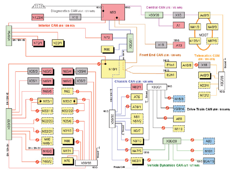
Full graphical representation of the 221-model CAN bus networks on the entire vehicle (courtesy MBUSA).
Throughout the years with its different models, Mercedes-Benz has used various CAN systems. This concept was first made practical in 1983 by Robert Bosch GmbH. Mercedes-Benz recognized its value early on, and was the first auto maker to introduce a CAN system in its vehicles. In 1991, the 140 model S-Class started this trend in inter-system communication. Today on the newest vehicles, there may be as many as eight different CAN systems — Diagnostic CAN, Central CAN, Interior CAN, Front End CAN, Telematics CAN, Chassis CAN, Drive Train CAN, and Vehicle Dynamics CAN. The reason for adding more and more CAN systems is because the existing ones would have been overloaded and unreliable. There are limits to the amount of information that can pass through a CAN bus before the network runs out of time slots for new messages. The use of so many control modules (now typically totaling over 50) and numerous sensors all communicating on CANs drives the need for updating and “growing†the infrastructure.
With so many computers on a network, there needs to be a ‘master’ or ‘overseer’ in charge. Depending on the model, this manager is either called the Central Gateway Module (CGW), or the Electronic Ignition Switch (EIS). Researching the vehicle you are working on will be needed to verify which is present. The EIS has typically been in charge from the late 1990s to the early 2000s until the introduction of the CGW. The functions of the CGW are to hold variant coding (model series, national version), be the gateway for all CAN busses connected directly to it, control all maintenance processing, monitor specified/actual CAN configuration, and monitor CAN bus idle (the function that tracks what is keeping a bus awake).Â
It should be obvious that performing any CAN diagnosis on one of today’s sophisticated vehicles will be expedited through the use of the factory DAS/XENTRY tool. Having the ability to communicate with the master gateway can be very helpful when troubleshooting CAN faults without hooking up directly to the bus. That said, however, 99% of the real-world problems you’ll encounter are due to what’s called “physical layer faults.â€Â In other words, damaged wires or connectors, resistances from corrosion at connections and grounds, improper voltages, and any other “mechanical†(as opposed to internal electronic) shortcomings in the network. These are all things that can be observed directly through careful visual inspection and electrical measurements. As a very helpful MBUSA engineer tells StarTuned, “What we’re teaching technicians is that XENTRY is not necessarily needed — only a meter, a wiring diagram, and a brain.â€
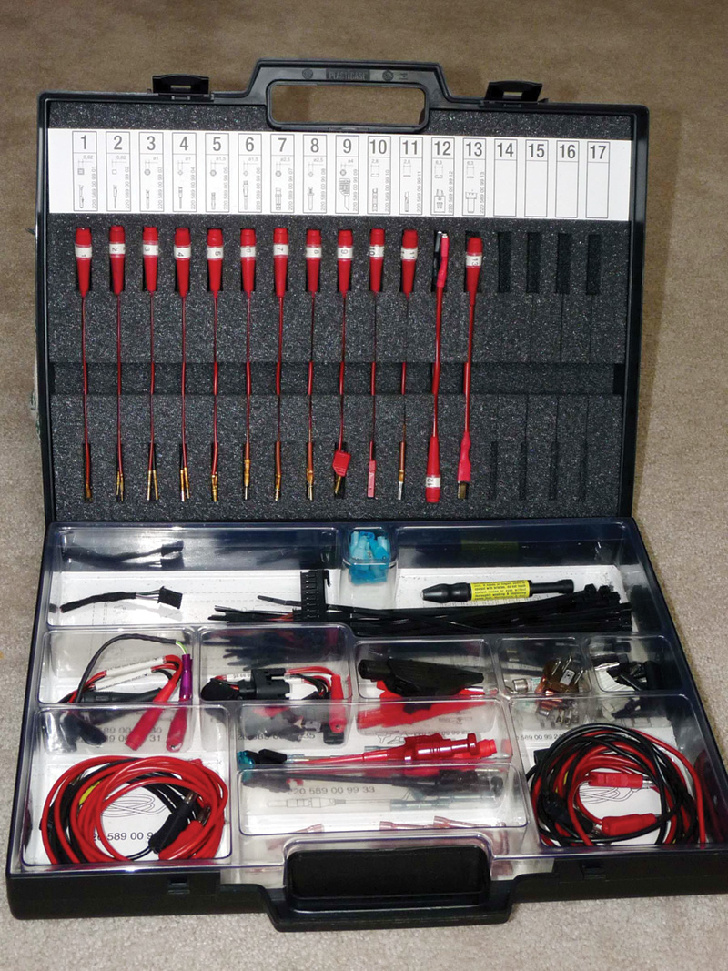
This Mercedes-Benz Electrical Test Kit Adapter Set is essential in not only ensuring good contact, but it also avoids the damage to the factory harness that might be caused by jamming an unsuitable object into the connectors when testing.
Volts, ohms, and patterns
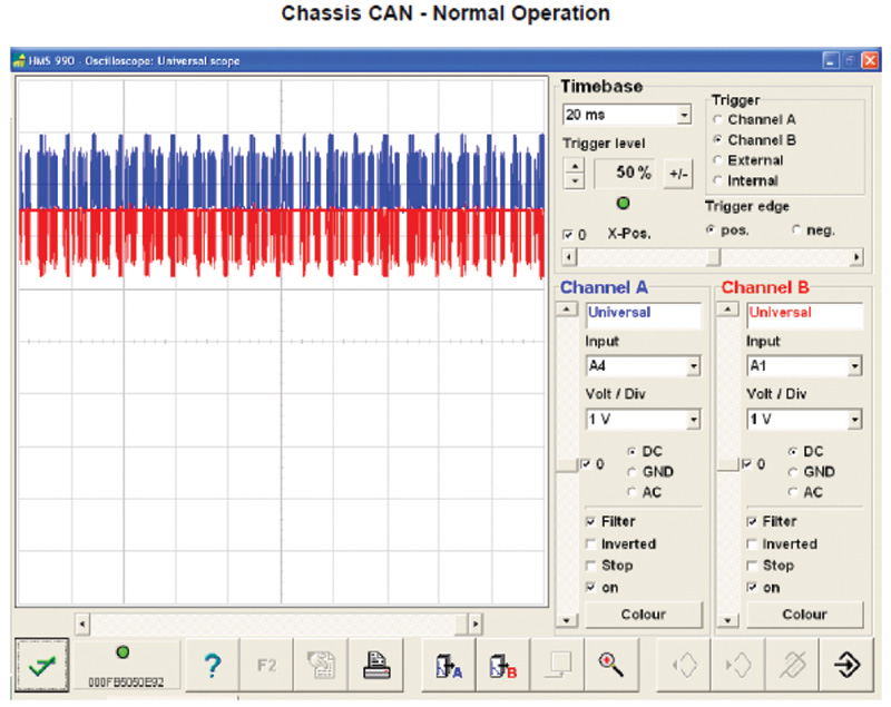
So, when attempting to troubleshoot any CAN failure, other equipment besides a factory scan tool will help. First, a Digital Multi-Meter (DMM) can be used to detect CAN operating voltages. If the reading is out of specification, you can then test to see if the CAN wires are shorted to positive, ground, or each other. Second, an oscilloscope is useful for analyzing the CAN signal pattern. A dual-trace lab scope is best to monitor both the CAN High and Low simultaneously to see whether or not the information matches, and that there are no voltage spikes, drop-offs, or abnormalities — you should be seeing a clean on/off square-wave pattern. Last, but not least, the tool that everyone should have to make diagnosing CAN systems easier while preventing damage to the electrical connectors is the Mercedes-Benz Electrical Test Kit Adapter Set, Part Number 220 589 00 99 00. It makes life a whole lot simpler to be able to tap into the separate networks with the exact harness adapters. With these tools, and the knowledge of how CAN works, you will be well on your way to diagnosing any type of CAN issue.
Knowledge IS powerÂ
Knowing how the CAN system is integrated into the vehicle you’re working on is Step #1. Without this knowledge, the scope of the problem will be a mystery. The research needed will include acquiring a map of the networked CAN system, and the locations of all the CAN bus connectors and control units. As we said, having a DAS/Xentry tool available is also critical. If you do not have these ingredients, diagnosing a CAN failure can be futile.
Let’s use a CAN issue on a 2008 GL 450 as an example. You don’t know the history of the vehicle, but you do know that the vehicle came to your shop “on the hook†and won’t start. You attach your scan tool and perform a “quick test.â€Â You determine that there is no communication with N80-Steering Column Module (SCM), N3/10-ME Control Unit (ME-SFI), Y3/8-Electro-hydraulic Control Unit (VGS), A80-Intelligent Servo Module (Direct Select), N47-5-Traction Control Unit (ESP), N51-Suspension Control Unit (Airmatic), N2/7-Restraint System Control Unit (SRS), N71-Headlamp Range Adjustment Module, and A76 and A76/1-Left and Right Emergency Tensioning Retractors (ETR).Â
All of these modules are on the Engine CAN. The two modules that have not been mentioned that are also on the same CAN bus are A1-Instrument Cluster (IC), and N73-Electronic Ignition Switch (EIS). These modules still have the ability to communicate because they are also tied into the interior CAN bus. The modules that you can communicate with on the Engine CAN (CGW, EIS, IC) all have communication codes pertaining to the problem. CGW has current and stored Code 9003 (“Coding of control module N93 Central Gateway Control Unit is faultyâ€). This merely indicates that specified and actual values do not match. You can verify this by looking at the specified/actual values in the Systems Diagnosis.â€Â EIS has event codes 9008 and 9009 (“No CAN message was received from control unit A80 Intelligent Servo Module for DIRECT SELECTâ€). IC has current and stored code 9100 (“The instrument cluster no longer transmits over the engine CAN databus. Status ‘CAN bus OFF’â€). These are all clues to what’s going on and further CAN investigation into “the big picture†needs to be performed.
Engine (CAN) C
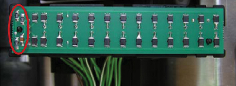
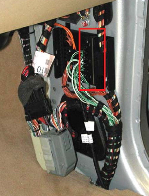
Circled are the terminating resistors that suppress interference noise. Whenever you encounter a CAN problem, always take the covers off the bus connectors to check for corrosion. If the carpet is wet, there’s a good chance that corrosion is present (courtesy MBUSA).
Researching the wiring schematic, you will find that all of these modules are connected to the X30/19 Passenger-side voltage distributor Engine (CAN) C connector located at the passenger-side front kick panel. Once that’s located, you can break out your handy Mercedes-Benz Electrical Test Kit Adapter Set and use the proper CAN test connectors to gain seamless access to the network. No need for paperclips, or, even harsher yet, insulation-piercing tools (which can lead to further CAN issues down the road if the holes are left exposed).
Install the Engine CAN C test connector to access the CAN High/Low resistance value. Your resistance value across the CAN High and Low should be approximately 60 ohms with the key off (CAN asleep). This value is actually acceptable for all networks because of the terminating resistors in the modules and CAN bus connectors. Terminating resistors were added to the CAN bus to help suppress interference noise and eliminate mirror messaging (basically, to act as a filter by cleaning the communication line).Â
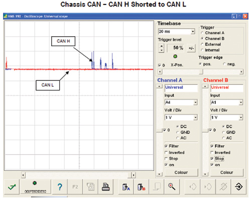
If a higher resistance reading is found, it indicates that a module is not communicating on the bus, or is not “on-line.â€Â If a lower resistance is found, it may indicate that the bus is shorted. For a shorted CAN High or CAN Low to ground, test the resistance of each circuit to ground. The CAN that is shorted will read 0 ohms. For a shorted CAN High or CAN Low to positive, you cannot check resistance to positive to determine which CAN is shorted because both circuits have voltage. You will have to look at the scope patterns to determine which circuit is shorted. Any loss of signal from a short will bring the bus down.
Mirror image?
If resistance is okay, the next plan of attack is using the oscilloscope. With a dual-channel scope, measuring the CAN High and Low simultaneously will allow you to determine whether or not the signals are an exact image of each other, or if only one signal has an issue. When looking at the pattern, as with any digital square wave, signs of a sinusoidal waveform, or voltage spikes are bad.Â
Likewise, having incorrect CAN baseline voltages indicates trouble. When testing any CAN system, knowing what the correct baseline voltages are is important. In the case of the GL 450, the Engine CAN C voltages should be approximately 2.6V on the High side, and approximately 2.4V on the Low side when the system is awake. Asleep, these voltages will be approximately 0V.
Once a faulty signal pattern is identified, disconnecting the CAN bus wires one at a time at the X30/19 connector will should be performed. This will help identify the faulty module that’s causing incorrect signals on the bus. You may now notice that all the CAN wires are not marked or identified in any way as to where they go or what module they are wired to. This is not an issue for anyone who has the factory scan tool that can communicate with all the modules in the vehicle. Simply leave the CAN wire disconnected and perform a “quick test.â€Â The module that you just disconnected from the bus should have an â€!†next to it. Any module that has this symbol assigned to it cannot communicate with the vehicle. This may mean that the communication link has been severed, the module itself is faulty, or powers/grounds are not present. If a module does not have power, ground, and a good CAN line, there is no way that it can function.
Removed from the equation
In this case, the N71-Headlamp Range Adjustment Module was the module causing the signal pattern to be corrupt, and when it was disconnected, the signal pattern looked “clean.â€Â After performing the “quick test,†the N71 also had an “!†next to it. But not so fast! The N71 module itself has a single bus wire going to each Left and Right Headlamp Range Adjustment Power Module (E1n3 and E2n3), which could cause the same scenario as a bad module. In this particular case, removing the connection from each headlight one at a time revealed that the Right Front Headlamp Range Adjustment Power Module was the culprit that was causing “everyone†on the CAN bus, including yourself, a headache.Â
While replacing the faulty module with a new part from your nearest Mercedes-Benz dealer’s Parts Department, you may notice that not only was there physical damage to the module (most likely from a collision in the vehicle’s history), but that the connector does not look too great, either. There are good ways and bad ways to repair connectors, but when it comes to vital communication wires such as those at CAN connectors, it is best to follow the Mercedes-Benz recommendations for repair. You know the saying, “When in Rome, do as the Romans do.â€
No-ohm repairs
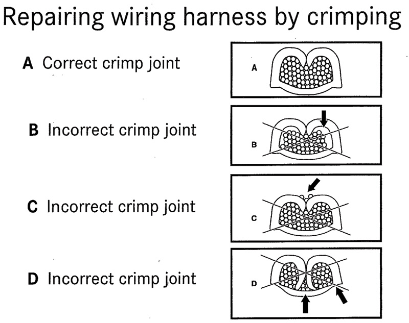
If new terminals need to be crimped onto the CAN bus, there are important rules to be followed. For crimping a joint, which is both electrically and structurally sound, you must pay attention to the following: wire cross-section, contact, the correct crimp tool and wire stripper, and tool adjustment. Crimping can be a delicate business. There should be no excess wire outside the crimp, or an excess of space inside, nor should the crimp claws touch the bottom of the wire so that it is bowed. The wires should be snugly enclosed in the casing.
The following methods of wiring harness repair have been approved by Mercedes-Benz: crimping using the special Raychem tool, Raychem soldering using special solder connectors and heated with a heat gun and special reflector to 400 deg. C., a combination of a Raychem repair method and cable tail repair (as in prefabricated cable tail wiring harness kits), soldering (using commercial solder for repairing connectors only), rapid connection technology using special rapid-connection wire blocks available in 2-, 4-, an 6-wire versions (not permissible for CAN lines)), and flat conductor pliers using special crimp contacts. Note that rapid blocks should never be used outside of the vehicle’s interior because they’re not waterproof.
As you can see, in the end both the problem and the solution make perfect sense, but when you don’t have a plan of attack for CAN issues, confusion can settle in quickly. Year-to-year, or model-to-model, some Mercedes-Benz vehicles may have similar control modules, but how they are networked is the key to understanding and diagnosing CAN failures. Having the right tools and accurate resources is also imperative. The success rate of going in blindly is not nearly as high as you will achieve by doing a little research beforehand, which will improve both your income and your reputation.Â




0 Comments