
Lots and lots of critical questions, and you’ll need your sharpest wits and the advice of the cam grinders to answer them accurately.
Â
by Adam Smith
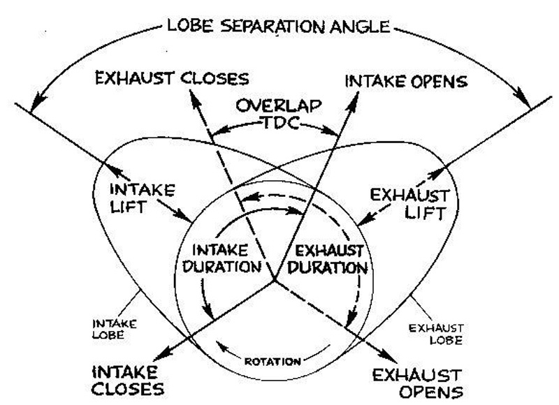
While there are a whole lot of subtleties involved, this simple drawing gives you the basics. Keep it in mind.
Considering all the underlying subtleties, camshaft design and selection is a complex topic indeed. It seems simple at first; when do you open the valves? When do you close them? How much overlap will work for your application? What kind of lobe separation angle (LSA) works best? Where do you want the lobe centers (LCA) for the intake and exhaust?  And of course what duration and lift figures do we end up with? But none of these things can be considered without looking at all the underlying pieces that make up the reciprocating assembly, intake, and exhaust conduits.
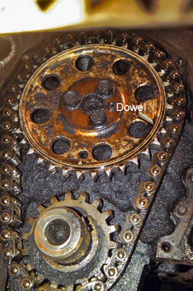
Old school: On traditional engines such as this 1967 Chevy 327, cam timing was determined once and for all by the position of the sprocket dowel.
An engine is a system and all the parts that make up that system must be considered when making a cam choice. When you consider the additional complications brought by variable valve timing or variable timing and lift systems, it can get really complicated… which is why you must utilize the tech resources that are available at the cam manufacturers if you hope to achieve the best possible result.
So why do we even need or want variable timing systems? Because with fixed timing systems the cam events are really only optimized for one specific, narrow, rpm band, sometimes only a few hundred rpm wide. Let’s look at fixed systems first, then examine some of the variable timing and lift systems out there today along with some of the limitations that retaining these systems place on our engine build.
It’s An Air Pump…Sort Of
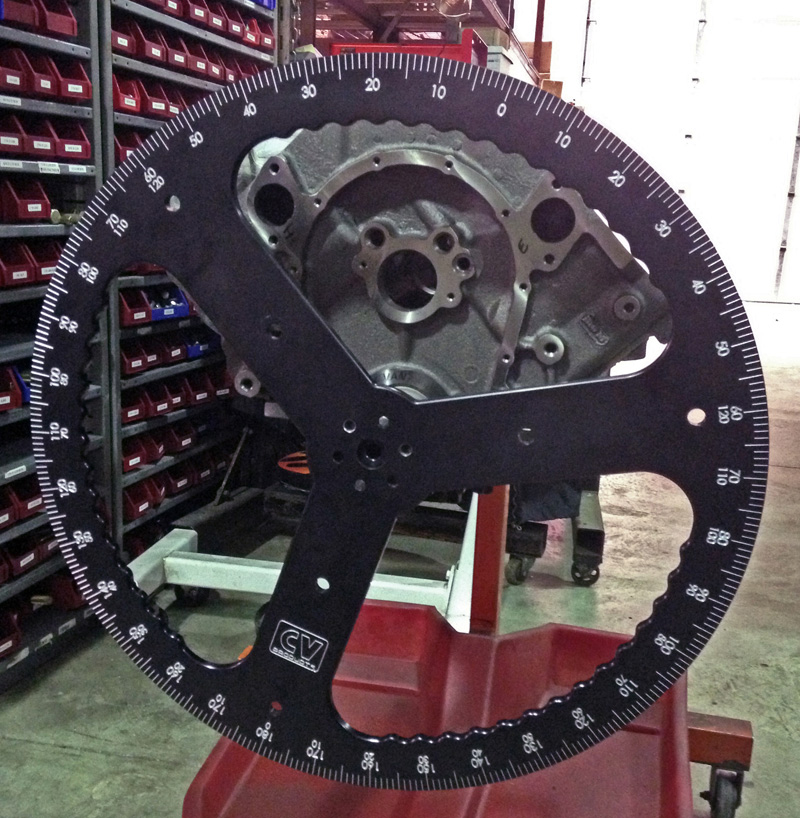
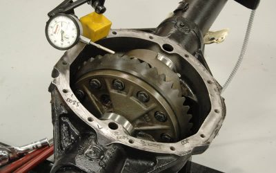
Everything that has anything to do with valve timing is referenced to the crank position, in degrees. An accurate degree wheel is an absolute necessity, made even more necessary when you’re installing performance cams in VVT-equipped engines. Not knowing your valve position relative to the piston’s location in the bore throughout the entire range of the VVT limits is a recipe for disaster.
While an engine could be simply described as an air pump or compressor, it’s a dynamic air pump that varies in efficiency and volume based on the physics of the cold and hot gas exchange cycles occurring during portions of the four stokes. To further complicate matters, these exchange cycles also have overlapping, shared events during which each affects the other. These cycles are also linked by common intake manifolding in most applications and by an exhaust system typically linked on at least half the engine… and the cycles are constantly varying in intensity due to changing rpm, throttle opening, intake pressure, exhaust pressure, pulsing, resonance, mixture, and timing.
Incoming air mass and density is affected by engine temperature, ambient temperature, humidity, and the fuel delivery system; a “wet throttle plate†fuel system that promotes evaporative cooling in the intake conduit charges the cylinder differently from a “dry throttle plate†system where fuel is injected either directly into the combustion chamber, or right at the back of the intake valve. The wet-intake evaporative cooling effect dramatically affects intake charge density, but the air volume – both the oxygen and the nitrogen (which acts as a buffer in combustion) – displaced by the fuel in a wet intake has to be considered. Charge density affects incoming charge inertia, which means that for any given bore, stroke, and rod length combination the intake valve may need to be open for a longer or shorter period to achieve maximum cylinder filling without going into intake reversion.
Blow down, etc.
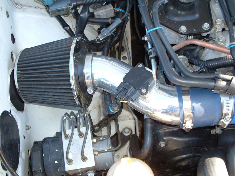
Even something as simple as the installation of a low-restriction air filter has to be taken into consideration.
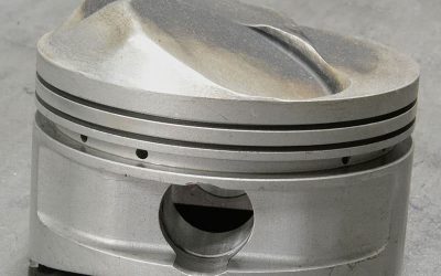
Then there’s part two: A more fully-charged cylinder changes the optimum exhaust valve opening timing (the beginning of “blow-down”), the timing of which affects both blow-down pumping losses and the pressure and velocity of the exhaust gases in the port and header, which in turn affects scavenging efficiency at overlap. Properly done, the exiting exhaust gases create a low pressure that helps clear the cylinder for the next intake event — it’s sort of like blowing across the top of a straw in terms of how it works — and the less residual exhaust left in the cylinder, the more room there is for fresh air and fuel to react in.
For minimum blow-down pumping losses, you’d like the exhaust to open as soon as possible and let the cylinder’s residual pressure vent the cylinder all the way down to exhaust system back pressure so the rising piston has almost no work to do, but in doing so you won’t extract the maximum work produced by the trapped expanding gases. While we always talk about “compression ratio,†the mirror image of compression is the expansion ratio… and that’s where the power is extracted. The main reason we measure compression ratio is because we can measure it and because it gives us a “mirror image†of the expansion ratio.
There are other considerations as well: What about the intake manifold? Is it variable in volume or length? Ported? Matched to the cylinder head to minimize turbulence in the intake conduit? Stock air cleaner and filter, or cold air system with a low-restriction/high-flow air filter? How about exhaust system efficiency? Are you running cast manifolds? How big is the exhaust system tubing if you’re running a full length exhaust? Pre-cats and/or catalysts? Mufflers? “H†or “X†piped? Headers? Stepped primary tubes? Large primaries? Four-into-two-into-one, or just a four-into-one? Are you running a merge or non-merge collector? Is the collector length tuned to the application, or is it just what you got out of the box? What’s the system backpressure at wide-open throttle at the top of each gear?
Then there’s combustion chamber design and shape. Are you running a stock head, or is it an aftermarket rolled head with a shallow fast-burn design? Ported? How about material? Aluminum in most cases, of course, but what about a purist who keeps the stock cast iron heads on his old musclecar? What must he do to compensate for that heat retention?  Cam and valve layouts come into play, of course. Single overhead, dual overhead, cam-in-block, cam-in-cam? Are you running a canted valve, straight valve, stock or larger-than-stock valve diameters? Are the valves shrouded by the cylinder wall? What about port shapes, flow rates, conduit volume, quench, or “squish,†as it’s sometimes called, tumble and swirl characteristics? (Tumble occurs when the air somersaults into the cylinder, swirl is when it rotates like a tornado.) What is the maximum designed engine speed and the application? All of the above may amount to question overload, but now you know why you need to talk to the experts when you select your camshaft. They’ll ask you the same questions during the process.
So Many Options, So Little Space…
While not a brand that’s typically hot-rodded, BMW was one of the early adopters of cam phasing. This is the single VANOS (a somewhat implausible abbreviation of the German variable Nockenwellensteuerung) unit, which operated on the intake camshaft only, and had just two phase-change points.
Variable valve timing comes in a number of different flavors, and the use of VVT is on the rise. There are discreet systems (think digital, only one or two states), continuously variable systems (analog!), single cam, dual cam, and variable lift systems. Plus, just about any combination that you can think of.
Cam phasing refers to a system that changes the installed lobe center of one or both cams and cam changing refers to systems that change the lift and duration of the cam. The advantage of dynamically altering phase and cam profiles is that you can optimize the lift, duration, and phasing for nearly the entire operating range of the engine. By moving things around, the camshaft goes from best at a narrow rpm band to best over the whole operating range.
Each manufacturer has a different name and acronym for its particular system, but for our purposes here we’ll just refer to them all as variable valve timing, or VVT. The first thing we have to consider is what each of these changes do and how each affects engine performance and output. With some cam changing systems, both lift and duration are controlled, as well as cam phasing. Other cam changing systems only control two or three steps of performance with two or three cam profiles (discreet system.)
As engine speed increases, the valve opening and closing timing events must occur earlier or later to optimize cylinder filling. Opening the exhaust earlier and the intake later moves the powerband up, improving high-speed torque and horsepower. This also changes overlap and cylinder scavenging efficiency, and by adding cam changing technology we can add additional control over mechanical duration and lift.
Duration changes are limited by the optimum valve opening and valve closing timing since duration is just the period between those events expressed as crankshaft degrees. Any increased overlap that would normally contribute to poor cylinder performance at low speed isn’t an issue, since the cam changes only occur at engine speeds well above idle. Increasing lift is essentially “free†in terms of power production, past the considerations needed to get the lobe profile smooth enough that the valve train is able to follow it without float or exceeding valvetrain component load ratings that an excessive rate-of-lift might cause. Vaulting the valve farther open only makes more power, so long as the valve is controllable and valve train isn’t damaged.
There are limits to this, of course. Once we get to lift points that are roughly 35-40% of the valve head diameter, the gains become so modest that more lift isn’t worthwhile, ASSUMING that the conduit is stable up to that point. If the ports are unstable, if the flow is unsettled or turbulent, all bets are off. While being able to change the cam sounds like it would be the better all-around solution, it does come with additional expense and complication. With the right camshaft installed, cam phasing systems are very affective and are cheaper and simpler.
The much more sophisticated Double Vanos not only dynamically adjusts the timing of both the intake and exhaust cams, but does so in an infinitely variable manner.
In general terms, advancing the camshaft opens the intake valve sooner, starts cylinder filling earlier, builds low rpm torque, decreases intake valve-to-piston clearance, and increases exhaust valve-to-piston clearance.  Tightening the lobe separation angle will, in general, move the torque band down, increase peak torque, narrow the power band, increase cylinder pressure, lower the detonation threshold, increase cranking compression, reduce idle vacuum and idle stability, increase overlap during both open- and closed-valve events, increase internal EGR, and decrease valve-to-piston clearances.
For single cam applications, VVT acts as a means to vary the cam installation point — we can advance it for better low-end torque and retard it at high rpm for better high-speed torque and power. It’s the same as being able to continuously degree-in the cam.
For dual-cam applications with the VVT on the exhaust cam only, changing the exhaust valve opening timing moves the torque band up and down. If we open the exhaust late, we get better part-load efficiency and more low-speed torque. At higher engine speed, opening the exhaust earlier improves high-speed torque and horsepower. Remember, horsepower is just (torque times rpm) divided by (5,252), so whatever you do to make the high-speed torque number better also nets you more horsepower.
With dual-cam engines with VVT on both the intake and exhaust cam, you get the advantages of being able to move the lobe separation angles, the exhaust valve opening timing, and adjusting both the open-valve and closed-valve overlap periods. Careful control of these parameters will allow smoother idle, lower emissions, a flatter and broader torque curve, and improved high-speed power. Adding cam changing just gives us more of the same, with the bonus of being able to finely tune low-, mid-, and high-speed performance and efficiency.
Going one better requires thought
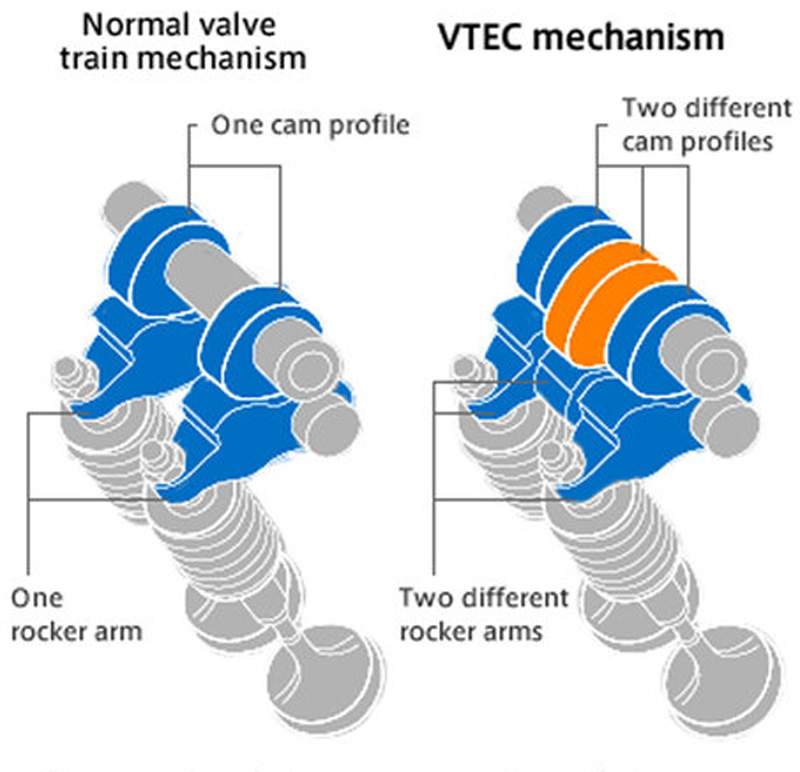
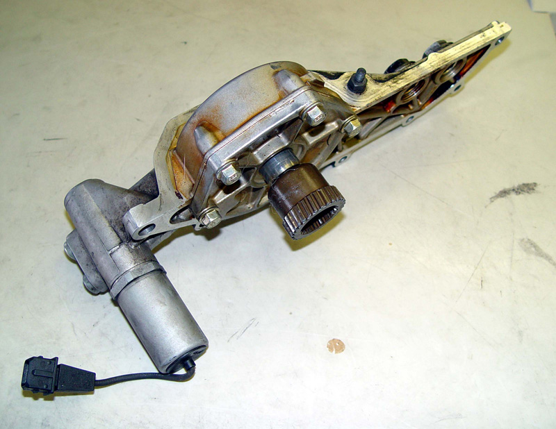
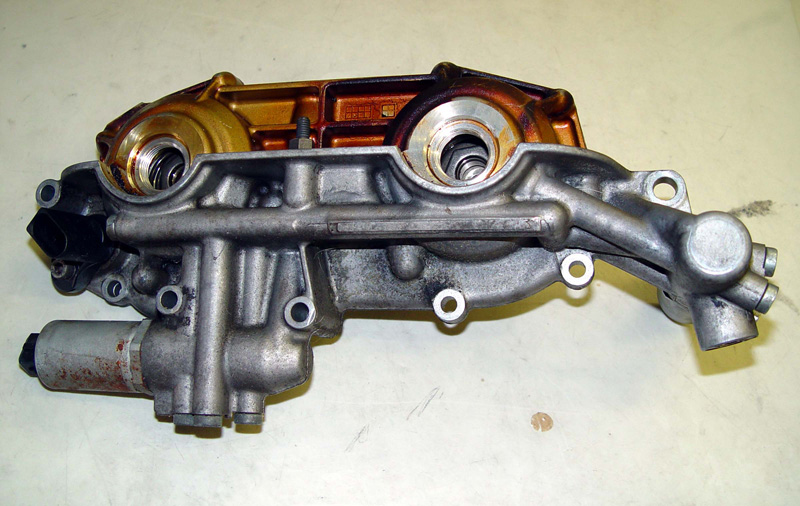
When Honda’s VTEC concept debuted in 1989 on the Acura Integra XSi/RSi, we were wowed. It goes beyond variable valve timing with variable lift. A sliding pin actuated by oil pressure engages a “hot cam” lobe. It was the first production engine to generate 100 hp per liter (courtesy Honda).
It all sounds so great, it must be too good to be true. When it comes to enhancing the performance of these systems, there are some limitations you must be aware of. Obviously, two things a performance grinder does nearly 100% of the time is increase lift and duration. If you’re upfitting a VVT-equipped car or truck, you must be cognizant of some potential trouble spots. First of all, the factory VVT phasers may have as much as 60 degrees of cam control. Not a problem for a low-lift, moderate duration cam, but possibly disastrous with a “hot” cam — you need to keep a safe distance between the valve and the piston, so you’ll have to check to see if phaser control needs to be limited. In some cases, kits are available to limit total control to something around 20 crankshaft degrees. Or, you may have to purchase new phasers compatible with your cam selection. For radial installations phaser eliminators are available.
Two, if you purchase a cam that requires a valve spring with more open tension to control the valve you are limited to about 375-385 lbs. of open pressure with the stock VVT phasers. Past that and the spring pressure may overcome the VVT operation and you may lose the ability to accurately control the cam timing.
Installing performance cams on a VVT engine means checking all the things you normally check: coil bind, valve-to-valve clearance, valve-to-piston clearance, and installed lobe centers, or valve opening events to confirm installed advance or retard, plus rechecking everything with the phasers activated at full limit. You could take someone’s word that everything will clear, or you could take the time to figure out how to check it and be sure because if it breaks, it’s your mess to make right. You’re the builder…
Â
Â
0 Comments