
The connecting rod and its bolts are probably the most highly stressed components in the entire engine, absorbing the compressive stresses of compression and combustion and the tensile forces that occur as the pistons wheels over top dead center in an unloaded state with nothing to cushion or slow its movement during the end of the exhaust stroke.
You’ve heard of the four-stroke engine cycle, but in truth there are seven cycles on a racing engine — or any non-two-stroke or non-rotary engine, for that matter. There are three phases to the intake stroke. The first is exhaust-driven during overlap when the negative exhaust pulse pulls through the chamber creating negative pressures reaching over 100 inches of water. That vacuum reaches right through the opening intake port and jerk-starts cylinder fill, then is followed by the normal pumping induction that occurs as the piston falls, pulling mixture into the cylinder at something around 10-20 inches of water vacuum. Final cylinder filling continues even after the piston reaches BDC and begins its upward journey. This is due to inertial ramming caused by the weight of the inrushing air fuel mixture, often lasting for as long as 60-100 degrees ABDC. This can occur because piston dwell over BDC is longer than dwell over TDC for nearly all engines and you’ll see this if you graph piston movement relative to crankshaft degrees.
Compression follows, then the power phase that lasts until the rate of expansion of the trapped mass becomes slower than the speed of the falling piston. At that point, the exhaust valve opens and the two phases of exhaust follow: blow down, which occurs due to residual pressure, and pump down, which occurs during upward piston motion. This completes our seven cycles and the whole exciting mess starts all over again.
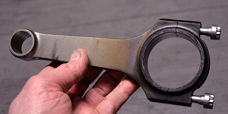
Controlling all of this commotion is the lowly connecting rod, the link pin between the rotating crankshaft and the reciprocating piston. The conversion of linear reciprocating movement to rotary movement couldn’t occur without this critical link in a piston engine. The forces battering the connecting rod alternate between compressive force (trying to shorten it) and tensile force (trying to pull it apart.)
As the piston rises on compression, it undergoes a relatively slow build-up of compressive strain, followed by the sharp spike of compression forces created when the cylinder fires and cylinder pressure rises rapidly. Forces are moderate over BDC on the power-to-exhaust transition, but shift rapidly to high tension over TDC at overlap since there’s no compression to catch the piston and slow it down. Over TDC at overlap it’s pure tensile stress… trying to yank the rod and rod bolts in two, and acting to distort the big end and small end as the piston moves from speeds of as much as 6,000 feet per second [Editor’s Note: That’s over 4,000 mph – Mach 5.2!], to a full stop to full acceleration away from TDC. It’s a miracle we don’t drive over thrown connecting rods more often than we do.
Connecting rods are made by a number of manufacturers; I’ve put the websites of some prominent suppliers at the end of this article for your convenience. What you buy and use is largely a matter of your personal preference and experience.
You need to know…
The key to keeping your reciprocating assembly alive is cleanliness, attention to detail, careful measurement, quality parts, and outstanding assembly techniques. Of primary importance is the selection, preparation, and technique used to install the rod bolts. In a nutshell, a rod bolt is nearly failure proof (assuming a lack of hidden defect) as long as it’s properly installed and tightened and you don’t stray outside of the design parameters by over-speeding the engine.
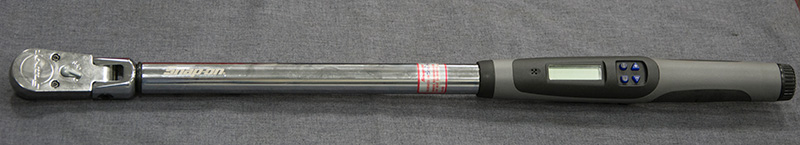
The only correct way to install rod bolts is by stretch. That is, measuring the change in the overall length of the bolt as it is preloaded. What we must do with a rod bolt is preload it to a higher load than the cyclic load to which it’s exposed. If we do this, the bolt will not see the cycling load at all. The bolted joint becomes one piece – solid — for that particular cyclic load. By preloading the fastener we force it to act more like a spring than a solid object; the cap and beam of the rod appear to be one solid piece. This is not something that can be accurately done with a torque wrench, which is more affected by thread and bolt under-head friction than by actual fastener loading. As you increase torque, this actually gets worse.
Using high-tech, manufacturer-specified lubes helps attain consistent tightening and reduces preload scatter, but it doesn’t eliminate it altogether. Most high-performance rod bolts have stretch specifications of something around .004 to .007 in. depending on the bolts and application. The stretch window is very small, sometimes as little as .0004 in.; that’s 4/10,000ths of an inch. In one application I use, the window is .0052-.0057 in. Cheap tools, technique, dirt, even oil becomes a factor when reading that small a dimension, and every bolt in every application has a different specification. Don’t guess. Go to the websites or make a call and get the exact specification for your application. Always use the lube the rod and bolt supplier specify because they have tested it on that bolt with that rod and they know that the torque or torque-plus-turns specification they give you to achieve preliminary stretch will work without overstretching the bolt. DO NOT experiment with home brews or cross-source lubes — use what they tell you. They have ruined and tossed enough bolts finding the right combination that there’s no point reinventing the wheel.
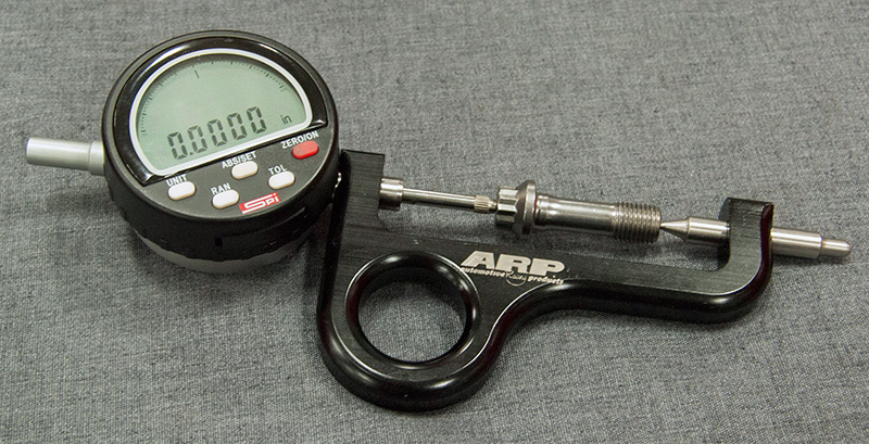
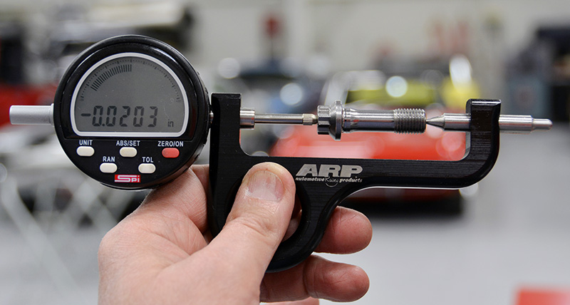
If you over tighten a rod bolt, you must relax it and re-measure it. If its relaxed length increases by as little as .0005 in., you may be required to discard it. In my experience, most bolts that are properly stretched will actually shrink in length when relaxed by about .0002-.0004 in., and I’m not sure I know why that is. I just know that I’ve got a modified ARP stretch gage that I’ve mated with an SPI dial indicator that will read to 5/100,000ths of an inch, and I’ve noted that nearly all rod bolts shrink slightly when properly stretched and cycled a few times. In the Navy, we called this PFM (Pure Freaking Magic), and while it’s not a scientific term it can be used to explain all sorts of mysteries . . .
To correctly tighten a rod bolt, you must lube threads, under the head, and the face of the cap with the approved lubricant. Turn the bolt in one smooth motion — do not stop — measure, pull again, measure and so on, a technique I call “chasing the stretch.†The reason is simple: Once you have pressure on the threads and on the interface between bolt head and cap, as you try to continue tightening the first thing you’re doing is winding up the bolt shank before moving the threads, inducing the kind of stress that produces an early failure. If you undershoot the spec, back the bolt all the way off, relube the area under the head of the bolt, increase your torque reading or the degrees of turn, and start again.
Types, advantages and cautions
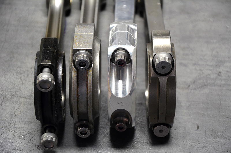
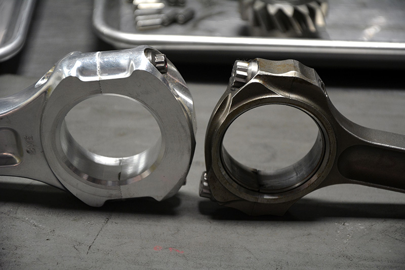
There are three materials that I’m aware of that are used to make connecting rods: steel, aluminum, and titanium. Most of us will end up using either steel or aluminum as titanium is generally considered cost-prohibitive. Steel has the advantage of strength, relative affordability, and durability. The disadvantages are the finished weight of the connecting rods and the fact that they are stiff enough to transmit everything happening in the combustion chamber right into the crank, and ultimately into the valve train. Titanium is light and strong, but it’s expensive as hell and it galls easily, so lubrication must be spot on and the oiling system must be superb at stripping entrained air. Aluminum rods are light, strong (when increased in cross section), and absorb and soften combustion energy, which makes them perfect for blown alcohol, fuel and wild nitrous combinations. On the other hand, they have to be replaced much more frequently than steel or titanium, which increases operating costs.
Your choice of material, length, and sizes are determined by your application. Connecting rod selection isn’t something you just go grab and then try to make everything else fit. Think deck height, compression height, stroke, fuel, application (drag or duration), blown or naturally aspirated (you can go with a lighter rod with a blower since intake pressure cushions the reciprocating assembly over TDC overlap) and rpm before you land on the rod you should use.
Prep and checks
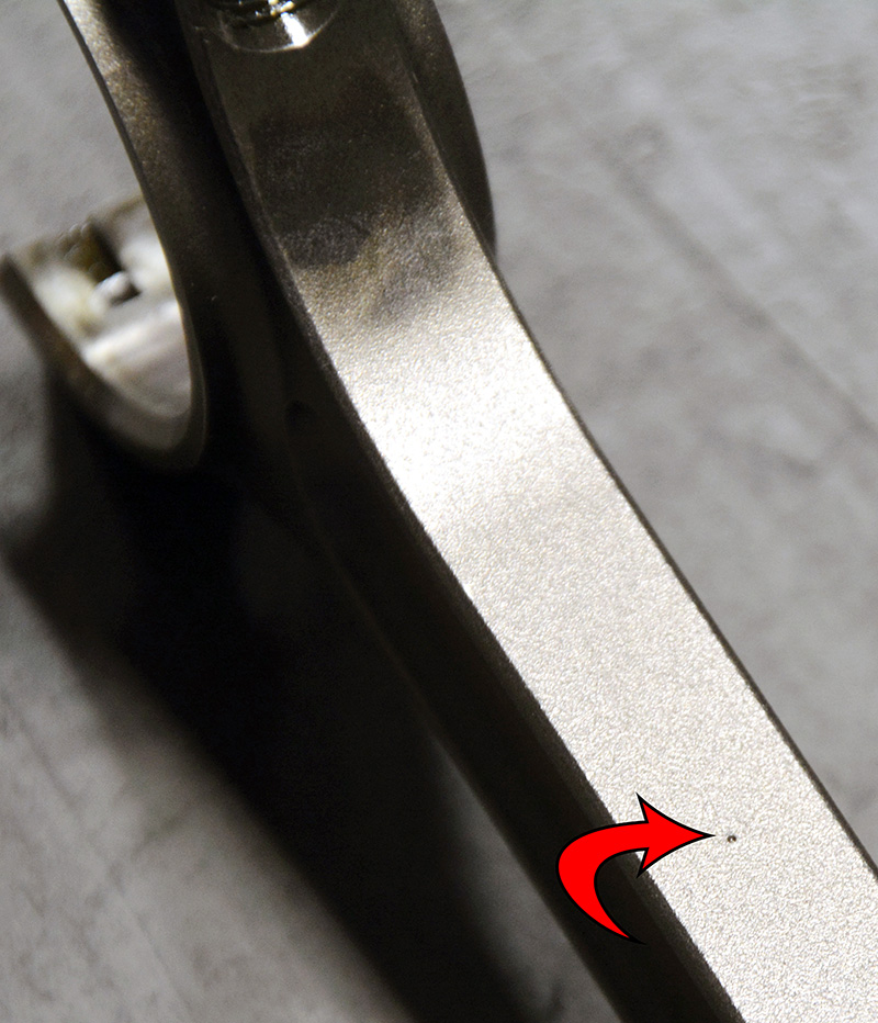
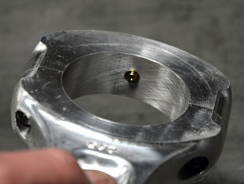
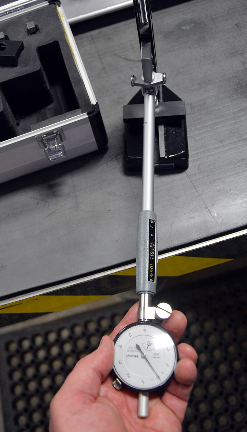
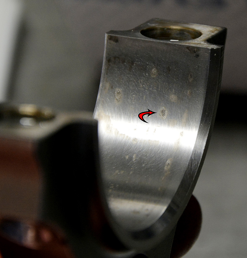
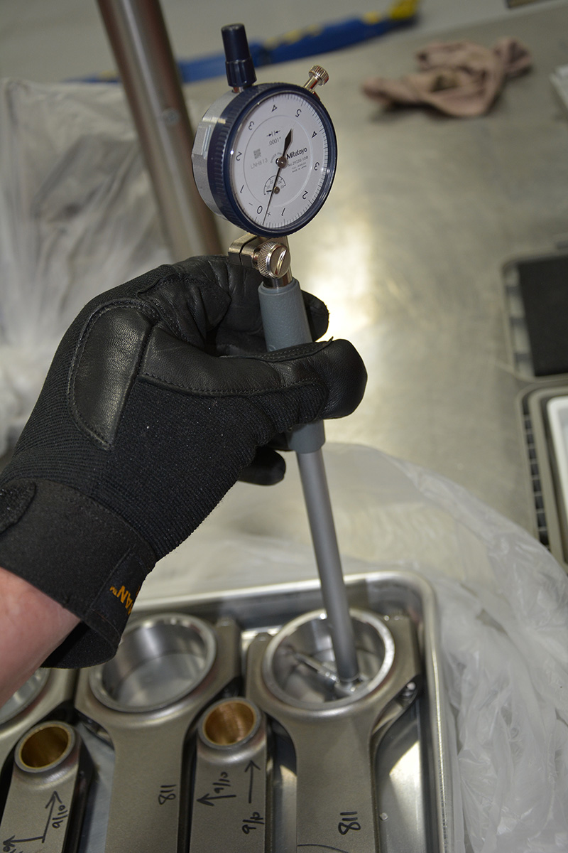
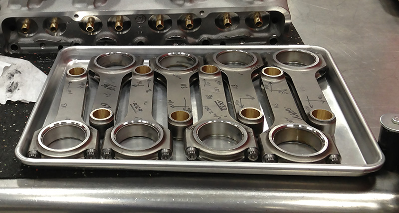
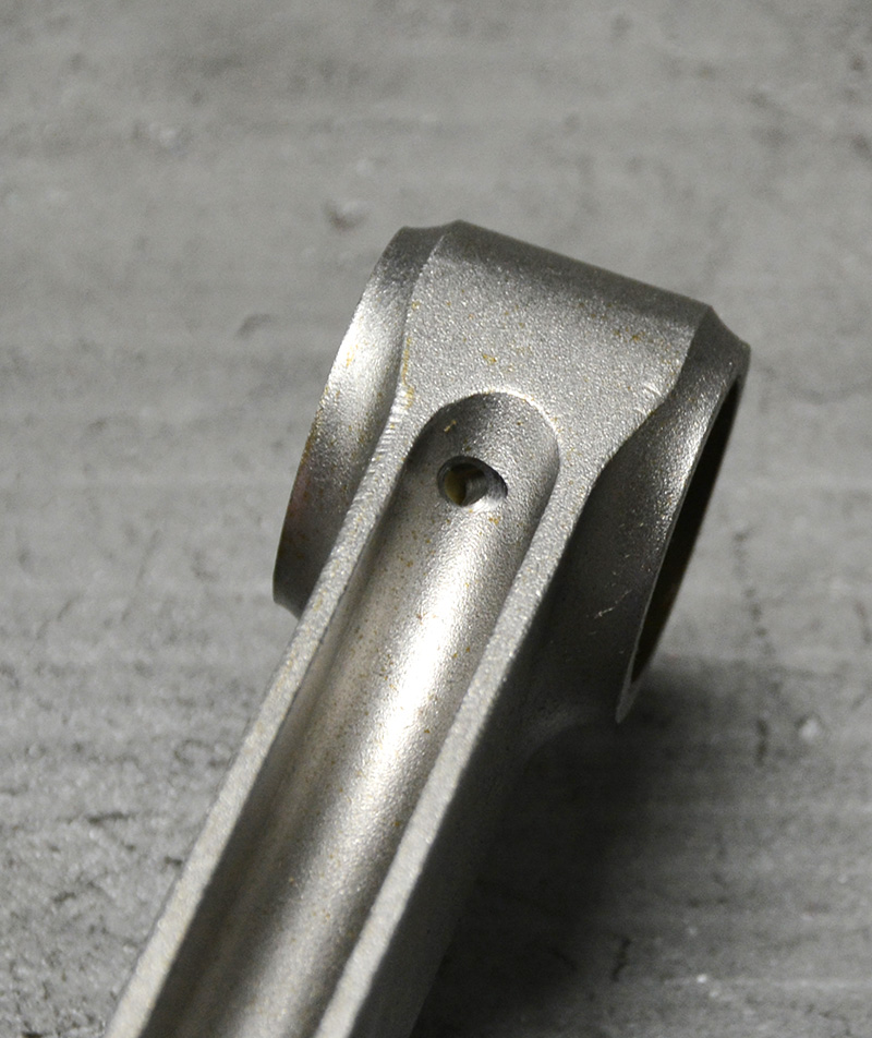
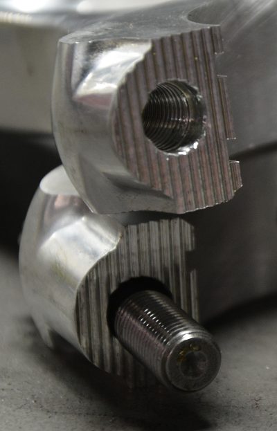
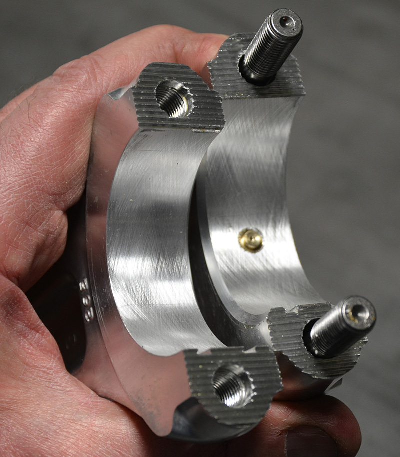
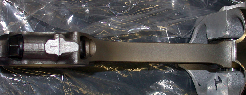
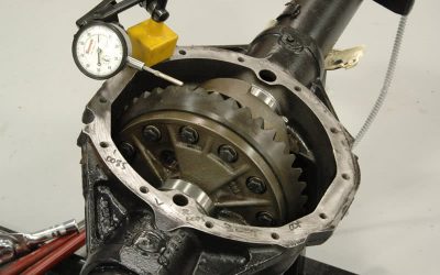
Whenever new parts arrive, always decant them and count. Got everything? Two bolts per rod? One pin per piston? Thirty-two Spirolox of the right thickness? Check them in and look them over for shipping damage. Wash and inspect for nicks, dents, dings and anomalies and check that the bearing offset chamfer is machined in. Clamp two rods in a vise next to each other as they will be on the journal, measure overall width of the two big ends, and check to see that this is .010-.020 in. less than the crankpin length as a preliminary side clearance check. Inspect the pin end and make sure the bushing oiling hole is drilled and lined up. Take a look at the parting lines on the cap and rod — dowels in place? Is the through hole in the cap relieved to clear the rod bolt radius? Everything final machined, straight, and smooth? Bores show hone marks as they should? Verify that the rod bolts are at full torque and measure the big end and pin end bores for dimension and concentricity, and calculate pin clearance for your application (more power means more clearance since you’re trying to compensate for bending forces.) Verify that both bores are round. There ARE exceptions to this. There are some very, very exotic high-end rods out there that may not have perfectly round bores, but unless you’re running Pro Stock, F-1, or NASCAR, you’re not likely to run into those exceptions.
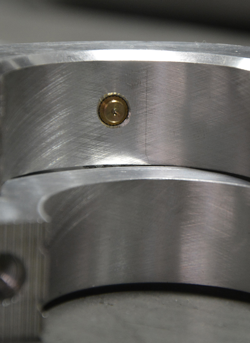
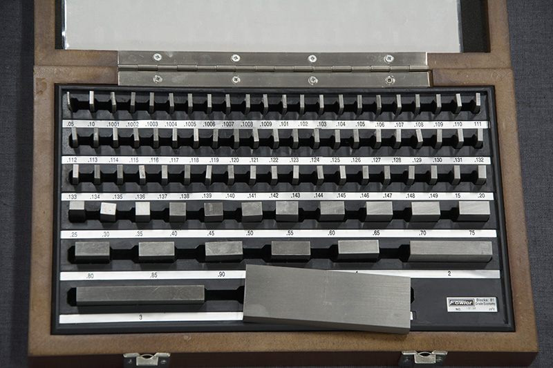
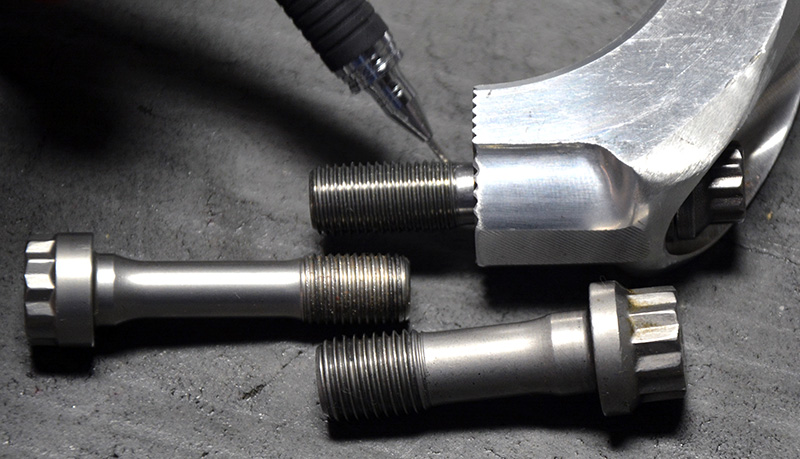
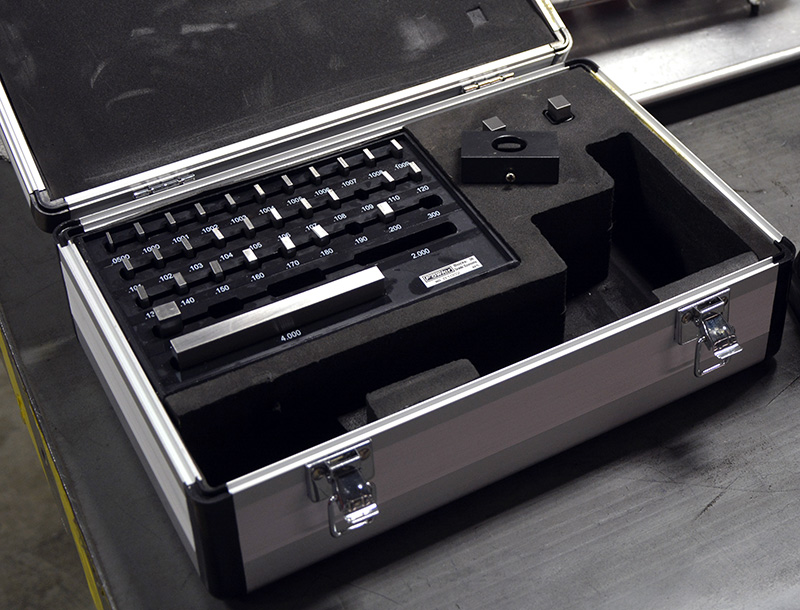
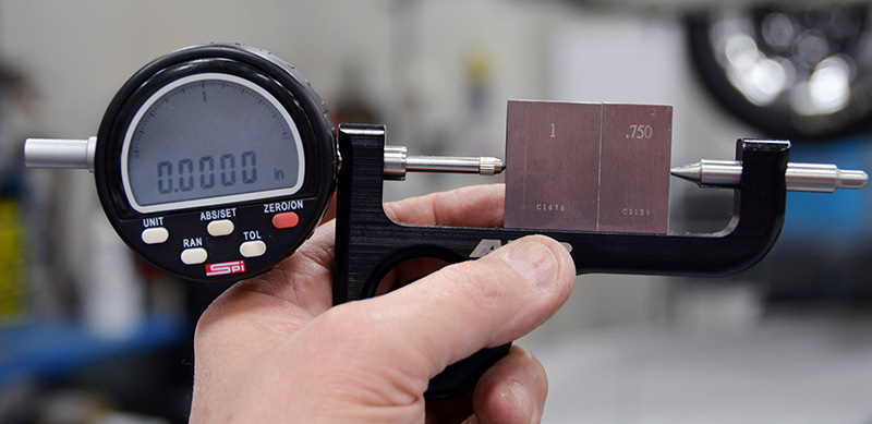
Mark rod bolts by location. I mark them 1 and 1L, 2 and 2L and so on for rod one opposite bearing locator tab slots and 1L for the bolt on the same side as the locator tab slots. Measure the overall length of the bolts and record that measurement. I set up my ARP stretch gauge with gauge blocks and record how much over or under my bolts are from that standard. Normally I use a 1.0000 and a 7.5000 standard for a total of 1.7500 inches and then record the over/under deviation for all my bolts. I’ve tried using micrometers, thread micrometers and height gauges, but nothing I’ve tried is as accurate as this method.
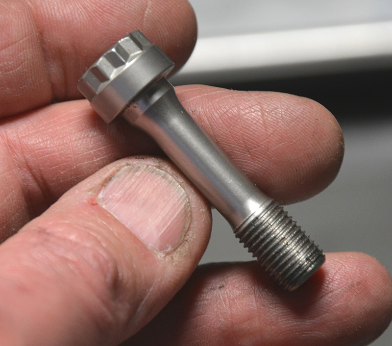
Inspect rod bolts for proper radii under the bolt head, properly-formed threads, and make sure bolts are completely free of nicks or dings. Cycle rod bolts five to seven times using the recommended lube at 70% torque to polish the thread ramp and the under-head-to-rod cap interface. It’s extra time and some say that with the new lubes it’s not needed, but my experience tells me otherwise. I get a much more consistent final stretch when I prep the bolts like this. Finally, run the bolts up to full stretch, loosen them and recheck overall length. Discard any bolt that remains .0005-.001 in. longer than your original measurement. You DID buy two extra “insurance†rod bolts, didn’t you? Nothing worse than being in the middle of your build with a bolt that failed first stretch and no spares . . . it doesn’t happen often today, but it can happen. In fact, that’s something else to remember: Not every bolt is exactly the same, and they don’t all stretch to exactly the same spec at the same amount of rotation. Start conservative and work your way up. Better to stretch them a couple of times and sneak up on it than to overshoot and ruin a bolt.
And In Summation…
Detonation, loss of lubrication, improper oil clearance, improper bolt preload, and over-speeding are the Big Five causes of rod failure, with 80% probably belonging to a loss of lubrication. You might see a product defect once in a blue moon, but it’s not likely. With good inspection and prep, you can race a lot of seasons and never see a rod failure — and that’s a good thing! It’s certainly not what we dealt with in the bad old days.
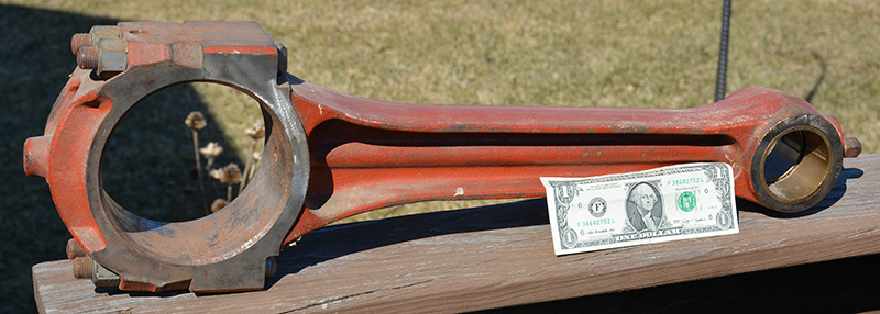
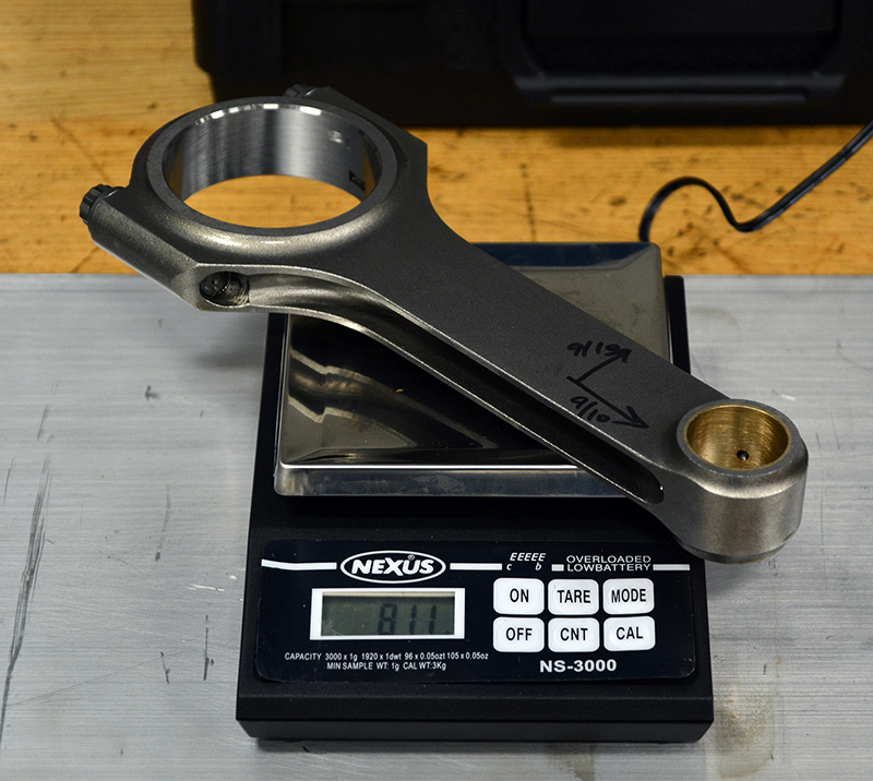
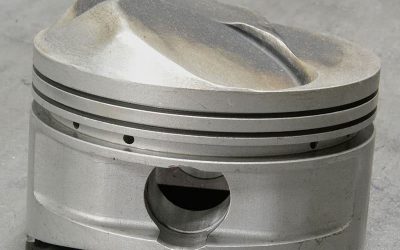
The next time you’re stuffing rods and pistons into a block, just take a minute and think about the job that 800-gram chunk of steel does — from dead stop to full velocity to dead stop over and over. A thankless job performed in millions of engines the world over day after day after day. It’s a wondrous little link pin that makes ground transportation and racing possible.
Resources
This list is far from comprehensive. There are many niche manufacturers out there for motorsport, motorcycle, watersports, and Asian or European specialists that make parts for a narrow range of clientele. I suggest that you perform your own search for rod and rod bolt manufacturers when you begin your project.
A-1 Technologies (bolt and stud manufacturer, no website located.)
https://www.arp-bolts.com/
https://www.spstech.com/home/
https://www.cp-carrillo.com/Downloads/Catalogs/tabid/82/Default.aspx
https://www.crower.com/
https://www.dyersrods.com/index.html
https://www.eaglerod.com/index.php?option=com_frontpage&Itemid=1
http://www.grpconrods.com/
https://www.manleyperformance.com/
https://www.mgpconnectingrods.com/
https://www.oliverracingparts.com/
https://www.rrconnectingrods.com/
https://scatenterprises.com/
https://pauter.com/parts/rods/
Excellent article…sure makes you think about that “little 283′ that you spun to 6 grand at every shift ..all weekend long!! and the others when you “ventilated” the block!
Nice work
Eric T
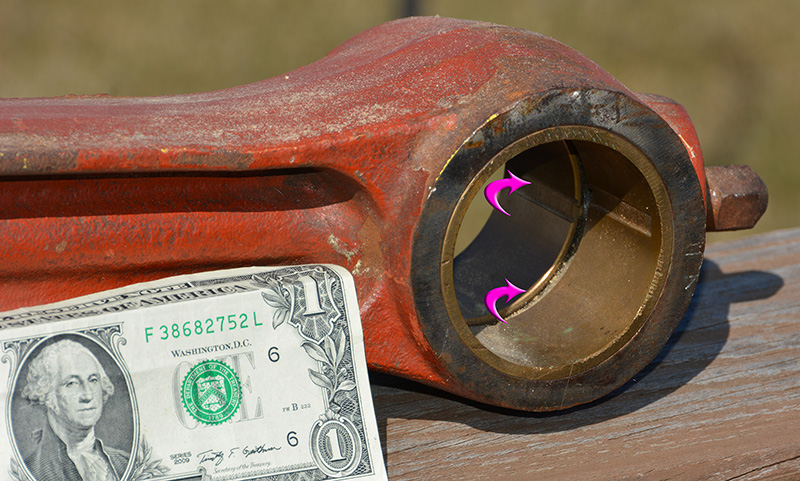
Liked the picture of the “walk to shore” [as we called them in the Navy] conn rod.
excellent – the rod bolt stretch data was particularly interesting, as my 1974 Pontiac Super Duty used that method, and I always was curious as to the real advantages. (It also used an 80 psi oil pump, but that’s another set of questions) Nice descriptions that are understandable with good backup photos.
Regards,
Mark A. Meyer