

Network topology, wiring diagrams and scan tools are essential for modern collision repair.
Not only are the electronics that enable the computerization of a vehicle vulnerable to heat, vibration, and water infiltration, many of the components are located in crush zones. Modules, sensors, and the terminals and wiring that connect them are primary areas of damage when impact occurs. For body shops in particular, the proliferation of electronics presents a dynamic and spiraling challenge: The traditional collision and mechanical repair realms are fusing.
New vehicles equipped with innovative electronics crash, too, and then need repair, often before they are brought to a dealership, let alone an independent facility, for mechanical service. The learning curve to keep pace seems like an inbound fastball, ready to blow by traditional competencies. Coping can feel overwhelming.
Put bluntly, body shops cannot provide complete repair today without an understanding of intravehicle communications, network topology, wiring diagrams, scan tools, and more. We must be able to discern and correct electrical damage sustained in an accident, avoid electrical- and electronic-related comebacks, and nurture a positive brand experience for customers. For modern, forward-thinking facilities and technicians, going ostrich is not an option.
.")
To learn how to visualize and understand a wiring diagram to become more efficient in collision repair, consider training from industry experts familiar with the rules, basic building blocks and fundamental patterns of Nissan electrical circuits, systems and topologies (courtesy Automotive Electronics Services Inc.).
Think like an Engineer

Becoming and remaining fully service-ready over time to provide collision repair has gotten complicated. Diagnosing, understanding and remedying electrical systems damaged in a collision takes a commitment to train and evolve in the four key areas above, and then being able to integrate competencies into everyday practices and procedures. (courtesy ManicMedia LLC.)
“Electrical systems need to work as the engineers who designed them intended, and technicians must know why they work the way they were designed,†says Peter Orlando, a technician and owner of Automotive Training Technologies LLC. “Like other automakers, Nissan scan tools and service information can be your friends, but they don’t necessarily fix every problem. Simply put, neither of them explains the operational strategy that engineers intended. But Nissan communication network topology diagrams and wiring schematics do. They fill in the blanks that service information may not explain, or which a scan tool cannot pinpoint.â€
“Technicians today must be critical thinkers, trained to be conversant with accessing, understanding and using network topology, wiring diagrams, and other essential tools. For example, intermittent electrical problems after a collision present unique challenges. Technicians must be capable of testing devices, wiring and systems without disturbing connections. In addition, failure to use genuine Nissan resources can limit the completeness of a collision repair. For example, technicians should be aware that third-party information providers often ‘edit down’ their wiring diagrams, sacrificing critical details for uniformity.â€
“The two main challenges that technicians face today are the need to pay attention to authentic wiring schematics and communication network topology diagrams,†Bob Augustine, a diagnostic technician and technical training director for Houston-based Christian Brothers Automotive, says. “To fully service a vehicle today, one must understand and be able to navigate the vehicle communication topology — which includes wiring diagrams, awareness of which communication networks are present and, importantly, how they are designed and actually interact.
“A full-function scan tool such as the Nissan CONSULT III plus, scope, digital multimeter, breakout box, and other tools can only do so much without them. In contrast to the Nissan CONSULT III plus scan tool, aftermarket generic scan tools are more limited. This is because to be price-competitive, aftermarket manufacturers choose to not license all datastreams and algorithms available to them. Consequently, generic scan tools may use a built-in communication network protocol that is not fully compatible with all of the communication network and gateway protocols used by Nissan vehicles,†Augustine continued.
“Nissan network topology and communication protocols have evolved over time. A 2001 model can be very different from a 2008, 2013, and future version. Earlier Nissans are primarily K-Line, later models added MSCAN, and more recently HSCAN protocols have been used,†he tells us.
“Controller area networks (CANs) have been on some vehicles for a long time as intravehicle networks. Newer protocols like High-Speed CAN (HSCAN) have been on some vehicles since the 2003 model year and were mandated for 2008 and newer vehicles. In addition, there are several other communication standards in use today and others emerging that enable more data to be exchanged more efficiently. For example, within five years, Nissan intends to deploy Wi-Fi network architecture that will enable advanced driver assist safety, possibly even self-driving functionality. Collision repair facilities and their technicians must keep pace.â€
")
Network topology diagrams provide technicians with a “lay of the land†overview. Color-coding can help technicians build quick associations between controllers and networks when problems arise. (courtesy Auto Tech on Wheels.)
Case Study: 2008 2.5L Nissan Altima with No A/C compressor Engagement
John Anello, a mobile diagnostic technician and owner of Auto Tech on Wheels, services both collision and mechanical service/repair facilities. He recently shared an example of how using the right tools — including network topology and wiring diagrams — helped him diagnose a 2008 Nissan Altima (2.5L engine) that after a collision had no A/C compressor engagement.
The first thing Anello did was to connect a Nissan CONSULT III plus to the Altima to confirm the findings of the collision shop. Using the scan tool, he selected the topology network view. “Network view is a feature that provides a technician with a quick visual mapping of the entire vehicle — using different colored icons for each control module and the different types of communication networks onboard — to visually denote if they have current, history, or no codes stored in memory,†Anello tells NTN. “I could see that there were no trouble codes within the PCM or any of the other controllers.â€
Anello then accessed www.nissan-techinfo.com to print a wiring diagram of the A/C system and search for related technical service bulletins. “The wiring diagram helped me understand how the A/C system was designed to operate once the A/C button was pressed. I was surprised to see that the Integrated Power Distribution Module (IPDM) was in charge of controlling A/C relay operation, but it was not grounding the relay when the A/C-on command was sent from the A/C panel. I then used the CONSULT III plus to navigate to IPDM data and saw the IPDM was not receiving a request to activate the A/C relay. This request was suspended somewhere in the network between the A/C panel and the IPDM.â€
Anello says analyzing network topology maps and relevant wiring diagrams led him to the cause. “They pointed me to which controllers were responsible for giving the final command. The topology diagram showed that the only computers on the CAN network that had more authority over the IPDM to activate the A/C clutch activation were the Body Control Module (BCM) and the Power Control Module (PCM).
“The scan tool confirmed the request was received by the BCM, so the problem had to be upstream. By closely looking at the PCM wiring diagram, I could see that the A/C pressure sensor was directly tied to the PCM to monitor the operating range of the pressure within the A/C system. Using the CONSULT III plus, I navigated the PCM data stream and noticed that the A/C pressure was at 0V, indicating low refrigerant pressure in the system. The PCM never set a code, but decided to keep the A/C clutch off due to a perceived low-pressure condition.
“But the A/C system was properly charged, so there had to be an issue with the A/C pressure sensor or its wiring,†Anello reasoned. “I discovered that the PCM was actually sending the five-volt reference to the IPDM, but the voltage was not exiting out of the IPDM, indicating the IPDM had an internal board problem. When I flexed the IPDM, I heard the A/C clutch engage and had the culprit.
“When this car was involved in the collision, the IPDM likely got damaged during the impact,†Anello concluded. “There was no visible damage to the unit, but the shock was enough to create an internal open circuit. There were no codes in the network for the scan tool to point me to any areas of concern, but knowing how the network worked and how to read wiring diagrams and scan tool data, the problem was solveable.â€
.")
Wiring diagrams allow a technician to “think like an engineer†because they illustrate the system strategies that control vehicle systems, controllers, sensors, and more (courtesy Nissan; color added by Auto Tech on Wheels).
Airbag Repair and Replacement Guidelines
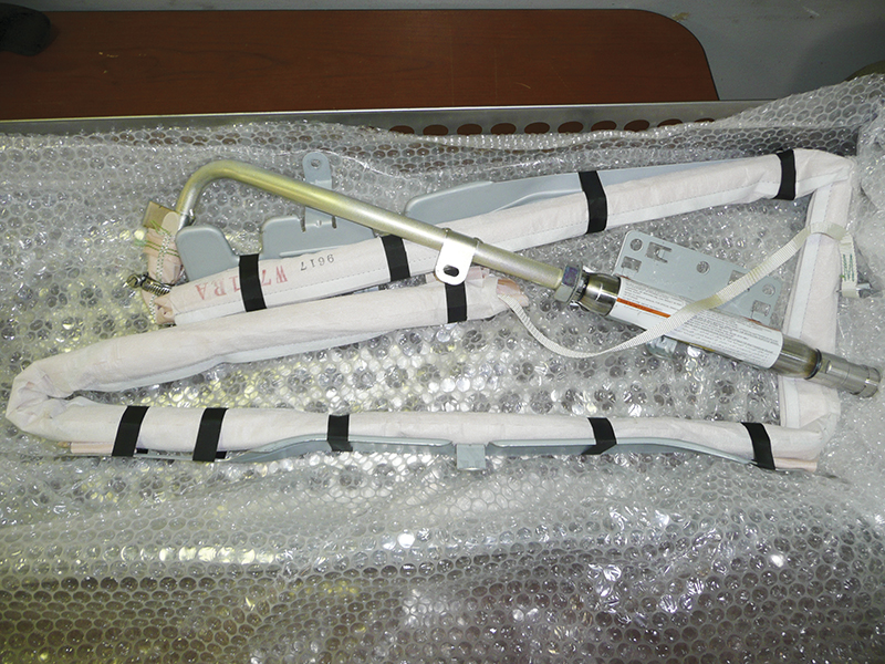
Nissan has a number of SKUs for airbags. Ordering the correct airbag is critical to minimizing cycle time. Each airbag unit, such as the 2012 Cube side curtain unit above, is shipped in bubble wrap to protect it, inside a perforated metal box designed to diffuse the impact if the unit is set off accidentally.
Nissan vehicles are equipped with the Advanced Air Bag System (AABS). The AABS-monitored circuits include the Airbag Control Unit (ACU), crash zone sensors, satellite sensors, front air bag modules, side air bag modules, curtain airbag modules, pre-tensioners, other pressure sensors, and all related wiring. Airbag deployment is based on information from these sensors, the crash severity, and whether the occupants are belted or unbelted.
Nissan cautions that all warnings and procedures contained in owners manuals and repair guidelines apply and must be followed. In particular, Nissan model-specific service information should always been consulted before any work on and around the airbag system is started. As examples, Supplemental Restraint System (SRS) wiring should not be modified or disconnected, unauthorized electrical test equipment and probing devices should never be used on the airbag system, and all collision repair work pertaining to AABS should only done by a qualified Nissan facility and technician.
Nissan has also authorized the Inter-Industry Conference on Auto Collision Repair (I-CAR) to provide collision repair training to facilities and technicians that repair Nissan vehicles. Visit www.i-car.com for more training information. Of note, the I-CAR website has a subpage, titled Airbag Parts Replacement Recommendations, which provides airbag replacement recommendations in chart form once a visitor inputs year/make/model data. Nissan vehicles are covered, but again, these guidelines may lag behind current Nissan service information.
The chart recommendations cover frontal, side, and rollover collision events. For our example, let’s continue with the 2008 Altima. Details cover two categories:
- Parts that must be replaced following airbag deployment — For frontal collision events, if the driver or passenger airbag has deployed, the airbags must be replaced with new ones and also be installed with new fasteners. Any pre-tensioners or damaged restraint system parts must be replaced with new parts. Sensors and electronic system components must be tested and replaced according to service information directions. For side or rollover events, some other actions are required. For instance, in a side collision, SRS components deployed in a side collision, satellite sensors, seatback assemblies and fasteners on the collision side must be replaced with new parts.
- Parts that must be inspected and, if damaged or faulty, replaced — Following a collision, inspect for and replace any SRS components and related parts that show visible signs of damage (dents, cracks, deformation). In addition, a diagnostic check of all SRS electronic controls, restraint system parts and wiring must be conducted; all parts identified as faulty must be replaced with new parts. Examples include undeployed airbags, steering wheels, wiring harnesses, connectors, terminals, seat belt assemblies, seat mounting points, sensors and others.
.")
For specific Nissan year/model airbag replacement recommendations, visit the I-CAR website at www.i-car.com and navigate to the page titled “Airbag Parts Replacement Recommendations,†which provides airbag replacement recommendations in chart form once a visitor inputs year/make/model data (courtesy I-CAR).
In both cases, Nissan emphasizes that new parts are the only option. New aftermarket replacement parts provide no guarantee that they will perform identically to Nissan parts, while used or salvaged replacement parts carry a substantial risk and liability for the collision facility doing the collision repair.
Given the important function that airbag systems serve, a visual inspection for damage is insufficient. Full testing of these systems is essential and required by Nissan. Similar to the A/C case above, the CONSULT III plus scan tool, network topology maps, and circuit wiring diagrams for the pertinent circuits are the primary tools to testing, diagnosing, analyzing, understanding, and planning a correct, complete, safe repair.
Increasing vehicle complexity loads body shops with more responsibility and liability to ensure that a safe, complete repair is provided. But in today’s marketplace, where a glut of information butts head with available time, shop managers face a difficult choice. They can become capable of in-house electrical diagnosis and repair, or they can utilize a mobile expert so equipped, or rely on another facility (e.g. Nissan dealership) that is fully service-ready for Nissan vehicle collision repair.
That choice boils down to how much control of the repair process a facility wants to have. Any choice other than complete in-house service-readiness provides a temporary stop-gap at best. There’s always an opportunity to improve service-readiness. Just don’t let time and technology pass you by.


0 Comments