
We are a demanding people. We want to buy high-performance cars, but we don’t want to deal with the hard-starting and “lumpy†idle that come with high-profile, long-duration camshafts. How can engineers make more power and yet still give us a smooth idle?

On early 112, 113, 119, etc. engines, only the intake cam had variable valve timing. Oil pressure and a spring kept the intake cam in the retarded position. The solenoid pulled on a shaft and altered the oil flow moving an inner piston along a helical-cut gear thereby advancing intake valve timing.
Think of an automobile engine as an air pump. That’s all it is, an air pump. The only difference is it is a self-powered air pump. We should all know the four phases of an Otto-cycle internal combustion engine: Intake, Compression, Ignition and Exhaust, in that exact order. Now, this may sound simple, but it really isn’t. Engineers learned a long time ago the timing of the intake, compression, ignition and exhaust determines the state of tune of the engine. If you have a portable gasoline-powered generator, you know that when you start the engine it only runs at one speed. An engineer will have designed it to open the intake valve, close the intake valve, ignite the air/fuel mixture, and finally open the exhaust valve allowing the spent combustion gases to escape all at the proper and most efficient time for that rpm. It’s not a particularly difficult task to design an engine to run efficiently within one specific rpm range.
Simple enough for a generator, but automobile engines don’t spin at one specific rpm. Instead, they must be able to make enough compression to start while being spun by an electric motor at 150 to 250 rpm, then continue to produce power up to 6,000rpm or more. Even though most cars are capable of doing this, it is not so easy to engineer. The problem is that at low rpm the air is flowing through the engine (the air pump) more slowly than at high rpm. The valve timing needs to match the air flow if efficiency is to be gained. This is known as the engine’s volumetric-efficiency — the amount of air that it can flow at a given rpm with the current valve timing. If an engine is designed with ideal valve timing for low revs, the air flow will be insufficient at high speed and restrict power output.
Valve Timing Limitations

On this early system, a repair requires the replacement of the entire camshaft. Speak with your Mercedes-Benz dealer’s parts specialist who can recommend all the hardware needed to do the job. This can save you several parts-acquisition trips.
If, on the other hand, an engine is designed to work best at high rpm it will “breathe†better and produce more power, but its volumetric efficiency will be low at low rpm. This means the car will be hard to start and not produce power until the driver revs the engine and gets it up into the “power-band.†If you were a mechanic in the 1960s, you may remember the procedure of “re-degreeing†a camshaft. By advancing or retarding the valve timing, you would change the relative position of the power-band. What if a system could be developed that could vary the valve timing dynamically so it could be retarded at low rpm, then advanced at high rpm? That would represent the best of both worlds: smooth running at low rpm, and the ability to generate more power at high rpm. Since as early as 1990, Mercedes-Benz has used variable valve timing to broaden the power band of its engines.
Early systems keep the intake camshaft in the relatively retarded position while starting and at low rpm, and advance the intake cam timing at higher rpm. The means of doing this are cleverly-conceived. Hydraulic actuators in the cam sprockets are used to vary the valve timing. Oil pressure is fed through an electrical solenoid valve to the actuator. At low rpm, oil pressure, with the help of a return spring, keeps the valve timing retarded. At higher rpm, the PCM energizes the solenoid. This action pulls on a valve in the actuator that redirects the oil pressure and moves the piston inside the cam sprocket actuator. The piston moves along a helical gear and changes the position of the sprocket relative to the camshaft. The grooves in the gear are cut to move the intake camshaft in the advance direction, thus opening the intake valves sooner.
Later-model Mercedes-Benz engines such as the M272 use “vane-type†cam actuators and vary the valve timing of both the intake and exhaust camshafts. This gives the engineers a lot of latitude in achieving volumetric-efficiency throughout a broader rpm range.
Exhaust Valve Timing?
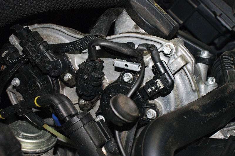
Looking at the passenger side bank at the front of the engine you can see the cam actuator solenoid mounted with three Torx bolts. Just to the left of it is the cam sensor for that actuator. Each actuator has its own cam sensor so the ME control unit can monitor what position the camshaft is in relative to that of the crankshaft.
While advancing valve timing to generate additional power is a good thing, there’s more to the story. Advancing exhaust valve timing would allow unburned fuel to exit the combustion chamber and increase harmful emissions. Retarding the exhaust cam timing, on the other hand, allows some of the exhaust gas to stick around for the next combustion cycle. Recycling exhaust gases into the combustion process has been done for years to reduce combustion chamber temperatures and cut NOx production. Exhaust Gas Recirculation (EGR) does just that – dilute the air/fuel charge for a cooler burn. By retarding the exhaust valve timing and leaving some exhaust gas around for the next combustion cycle you achieve the same thing. In fact, this is known as the “EGR Effect.†Federal emissions regulations require that a manufacturer do all it can to reduce harmful emissions and increase fuel economy. This is why the M272 motor and others vary the valve timing for both intake and exhaust camshafts.
You can monitor the position of the intake and exhaust camshafts on your Xentry software SDS. The values are given in degrees, which indicate the position of the intake and exhaust camshafts. The positions are read by the cam position sensors and they are compared to the signal from the crankshaft position sensor. On later models (272 and later), there are four cam position sensors — right intake, right exhaust, left intake, and left exhaust. With this array of sensors the ME control unit can determine the engine’s exact position with the ignition key on even before the engine is cranked, which helps reduce crank times. It also allows the cam position to be monitored relative to the crank position, and the variable valve timing to be measured and controlled. Of course, it can also detect if there is a problem. If a cam sensor stays in the advanced position or does not return fast enough, the ME can figure out if the actuator is sticking.
If Actuators Rely On Oil Pressure…?
 with a paid subscription to www.startekinfo.com. You will also see what special tools, if any, are required to do the job. Here, we are measuring the basic setting of the intake and exhaust cams.")
If you have diagnosed a bad camshaft actuator, you can access step-by-step repair techniques on WIS (Workshop Information Systems) with a paid subscription to www.startekinfo.com. You will also see what special tools, if any, are required to do the job. Here, we are measuring the basic setting of the intake and exhaust cams.
Each of these actuators (two intake and two exhaust on V8s) are of the vane type and rely on oil pressure to help the actuator move between the advanced and the retarded position. If the improper (non-synthetic) oil is used, sludge can develop in the actuators causing them to stick in either the advanced or retarded position. This can cause the ME to flag a code. This is one reason it is critical that only Mercedes-Benz approved engine oils are used at the recommended service intervals. If the camshaft actuators are sticking, you will need to replace them. This is the equivalent to doing a timing chain job since the cam sprockets will need to be removed. If you are servicing the actuators, make sure you have all the proper tools for setting valve timing, and carefully read the instructions for the procedure. Each actuator must be in the correct position when it is installed on the camshaft. With a paid subscription to www.startekinfo.com, you will have access to the proper procedures and a list of the special tools required, if any, to complete the job.
As with any electronically-controlled system, you should back up your scan tool results with electrical and mechanical testing. The basics should not be overlooked when diagnosing a problem. Keep in mind that if you test the cranking or running compression when you suspect a stuck camshaft actuator, your readings will show only subtle differences from one bank to the other. The diagnostic trouble code (DTC) present should direct your testing. If you have a circuit code for a camshaft actuator solenoid, you should verify that you have voltage to the component with the key on, and check the integrity of the wire from the actuator to the control unit. This is quite simple since the control unit is mounted on top of the intake manifold. You can use a DMM or an oscilloscope to watch the control unit switch the actuator solenoid on and off. If the control unit is not advancing or retarding the valve timing, note if it is pulsing the solenoid to ground with a very small duty cycle. To change the valve timing, the ME control unit increases the duty cycle of the cam actuator solenoid to ground. Â
Seeing What the ME Sees
. The third trace is the control of the actuator. Notice the duty cycle change as the cam is actuated in the beginning of the pattern. The bottom trace is the amp draw of the solenoid. It pulses with the actuation and averages about one amp when activated.")
This oscilloscope is monitoring the driver’s side intake cam. The top trace is the crank sensor — notice the TDC cutout in the pattern. The second trace is the cam sensor pattern (each cam sensor pattern is unique). The third trace is the control of the actuator. Notice the duty cycle change as the cam is actuated in the beginning of the pattern. The bottom trace is the amp draw of the solenoid. It pulses with the actuation and averages about one amp when activated.
If you have a dual-trace oscilloscope, you can watch the relationship of the crank sensor and cam sensor signals while actuating the solenoid through your Xentry SDS unit. Under “Actuations,†you can control each cam individually and watch the degree readings change. You will be directed to rev the engine to between 3,000 and 3,500 rpm to perform the test. You can also see the cam/crank sync change on your scope if everything is working properly. Older Mercedes-Benz engines such as the 112, 113, and 119 used AC pulse generator crank and cam sensors. Cam sensors evolved into three-wire Hall-effect sensors. The more modern M272 engines and later use three-wire Hall-effect sensors for both the cam and crank sensors. These newer sensors require a reference voltage, signal voltage, and ground. Scope the signal wires for the cam and crank shaft sensors.
You will see consistent pulses with a single TDC pulse from the crank sensor. The cam sensor will have four for each revolution. By the way, if the camshaft impulse wheel (what passes by the cam sensor) needs to be removed to service other components, it must be replaced. The mechanical work of setting up the VVT actuators will be covered in future issues of StarTuned. Understanding how these systems work should give you a greater understanding of what to do if something goes wrong. Consider your Mercedes-Benz parts supplier as your partner in this effort.


0 Comments