Some people consider the vacuum gauge a lowly instrument that might have been part of a DYI tune-up kit decades ago. Think about it for a minute, though, and you’ll realize how basic and important the info it gives you really is.
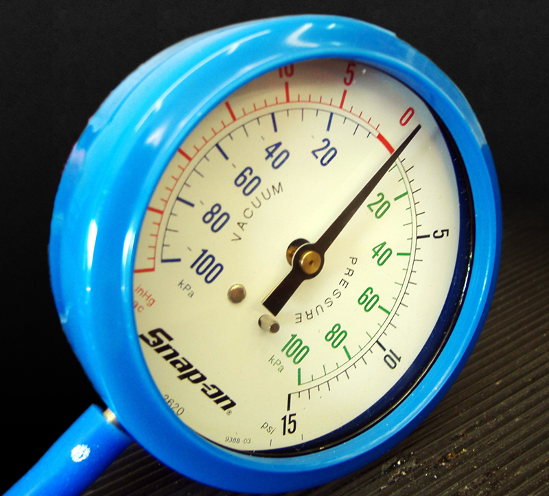
Once you learn to properly interpret its readings, a vacuum gauge can be one of the most useful tools in your toolbox.
A vacuum gauge may be one of the most powerful diagnostic tools in your toolbox because it shows you the actual vacuum produced as the pistons draw air into the cylinders. The readings that you can see can help you diagnosis many engine problems such as vacuum leaks, sticking or burned valves, flat camshaft lobes, weak valve springs, leaky piston rings or head gaskets, worn valve guides, and a restricted exhaust system. The readings can also help in tuning the ignition spark timing and the air/fuel mixture.
The vacuum produced by an engine as it is powering a vehicle down the road is a very good indicator of the operating load conditions. A typical engine should produce 17 to 21 in. Hg (inches of mercury) of vacuum during light load, but this will drop below 5 in. Hg when it is operating at high-load conditions such as wide-open throttle acceleration, or pulling a trailer up a steep grade.
The normal vacuum reading of a properly-tuned engine with a stock/mild cam is in the 15 to 21 in. Hg range at idle speed or faster with the engine unloaded. When the engine is accelerated under load, the vacuum should drop to near zero then slowly rise up as engine rpm increases. During decel, the vacuum may rise to 25 in. Hg inches or higher. An engine with a high-performance cam will have a lower vacuum reading at idle, but it should be close to that of a stock engine at higher engine speeds.
A stock engine with worn piston rings will have a slightly lower vacuum reading at idle, plus the vacuum will not get as high on deceleration as in a healthy engine. An engine with “sticky valves†will cause the vacuum gauge to pulse or flicker at low engine speeds. An engine with worn valve guides, burned valves, leaking or poorly-seated valves will cause the needle to move in a regular sweep or pulse of 3 to 8 in. Hg at idle speeds. If the vacuum readings are normal at idle, but begin to pulse or flicker as the engine speed is increased, broken or weak valve springs are most likely the problem.
Low engine vacuum can be the result of a lean air/fuel mixture and/or retarded ignition timing. A lean mix at idle can cause surging, and the reading will slowly sweep up and down. A restricted or plugged exhaust system can cause the vacuum reading to gradually drop as an unloaded engine is sped up.
Vacuum will be at its highest when the ignition timing and air/fuel mixture are tuned for maximum power, but avoid over-advancing the spark timing because it can lead piston failure from detonation/pinging issues.
The computer of a modern fuel injected engine references the vacuum along with the throttle position, the density of the air and the volume of air, as determined by mass, that the engine is consuming to determine what ignition spark advance setting is needed at any given time. The vacuum signal is used as part of the calculations that determine when the engine needs to be fed a richer air/fuel mixture when operating under high-load conditions.
Tuning timing via the gauge
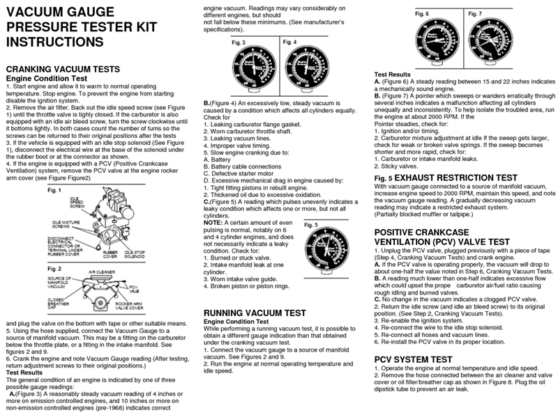
This set of instructions that came with one of our vacuum gauges shows a few of the tests it can be used for.
The first rule in performance tuning is to tune the ignition system before tuning the air/fuel mixture. Adjusting the ignition timing using a vacuum gauge can be done, but it isn’t as simple as it sounds because many older engines have an initial spark timing setting plus both mechanical (rpm) and vacuum spark timing advance systems. The ideal spark timing will cause the pressure in the combustion chamber to be at its maximum when the piston is at approximately 12 deg. after top dead center. The amount of ignition spark advance it takes to get the combustion timed correctly varies with the rpm, the air/fuel mixture, the temperature inside the combustion chamber, and cylinder pressure (how full each cylinder is, which will vary by the throttle position).
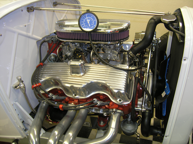
This vacuum gauge is being used to observe what the manifold vacuum is on this 348 Chevy while the automatic transmission is in Drive.
The initial timing that will cause the engine to create the highest vacuum reading will often also cause it to kick back against the starter during hot engine cranking. Typically, 10 to12 deg. BTDC of initial timing works quite well on an engine with a stock/mild camshaft (duration of the camshaft is less than 220 deg. at 0.050 in. of valve lift), but if the engine has a high-performance grind it may respond well to more initial timing. The initial timing settings we use for an engine with a high-performance camshaft with a duration of less than 240 deg. at 0.050 in. is 14 to 16 deg. BTDC. If the duration is more than 240 deg., but less than 260 deg. at 0.050 in. of valve lift, we use an initial timing setting of 18 to 20 deg. BTDC.
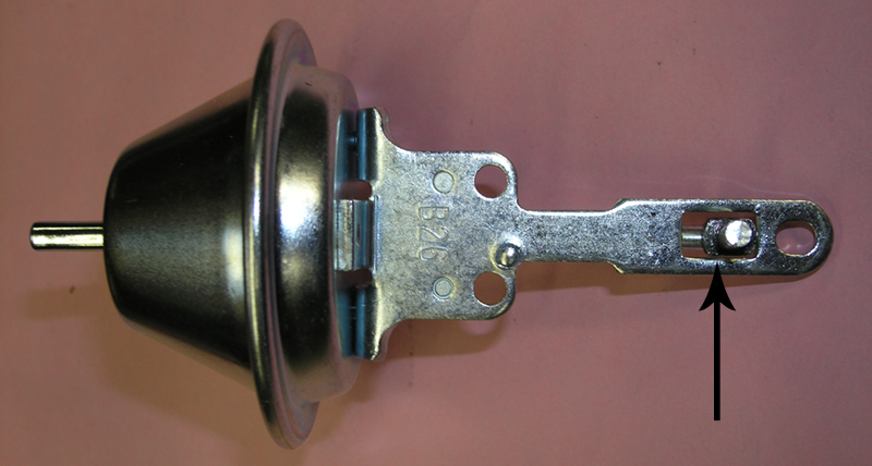
The arrow in this picture points to the bushing that was used to limit the vacuum advance to 10 degrees of spark timing.
The timing at idle will also vary depending on whether the engine uses ported or manifold vacuum for the vacuum advance system. Many tuners prefer ported vacuum for the vacuum advance because the timing at idle will remain the same regardless of the vacuum level at idle, but some tuners prefer manifold vacuum for the advance system. If you use manifold vacuum for advance, the mechanism should be fully advanced at 2 in. Hg lower than the engine will have at idle (in gear with an automatic transmission). Always remember that the vacuum at idle will also be lower at higher elevations such as during a trip to the mountains.
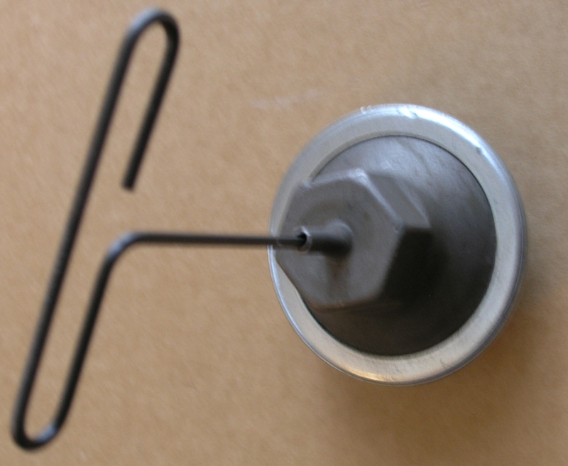
The Allen wrench in this Ford vacuum advance can is used to adjust how much spark timing advance the engine will get from this mechanism.
The method many people use to adjust the timing with a vacuum gauge is to advance or retard the ignition until the highest steady vacuum reading is obtained, and then retard the timing until the vacuum gauge reading drops slightly. But remember most carburetor-equipped engines have both mechanical and vacuum advance systems. The mechanical advance is used to provide the amount of spark advance it needs for maximum power, and the vacuum system adds the extra advance an engine needs to burn the leaner air/fuel mixtures encountered at part throttle, thus providing the best fuel economy. In both cases, you may need to retard the timing from the setting that gives you the highest vacuum reading to prevent engine damage from detonation/pinging problems.
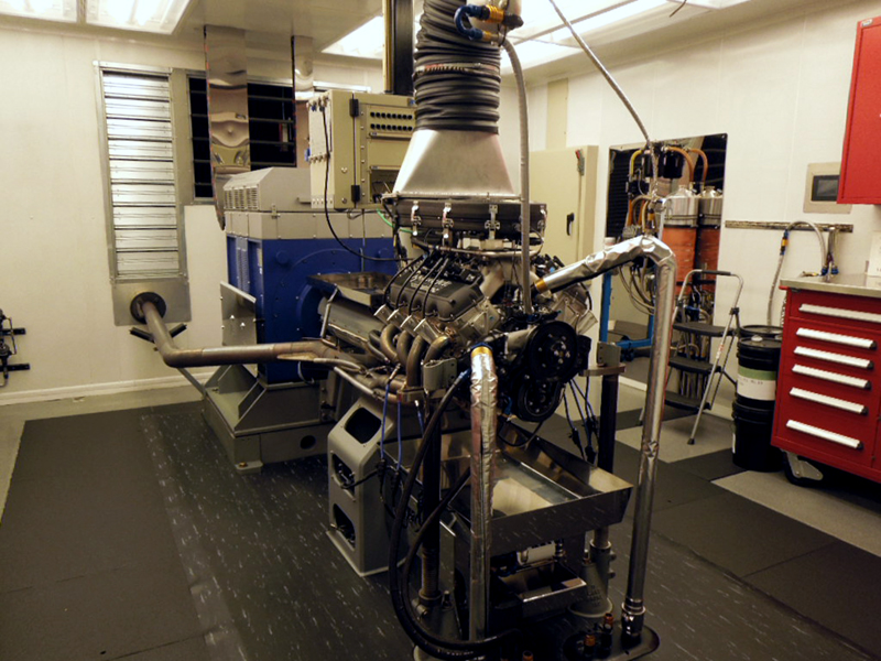
Both the intake manifold vacuum and the air charge temperature readings of this Hendrick Motorsports engine are being monitored on the dyno so tuning can be done to match the conditions of real-world racing. Attention to details such as these is part of the reason the team wins so many NASCAR races.
Most vacuum advance units were designed and calibrated for leaded gasoline (which was phased out beginning in 1975). Today’s reformulated unleaded gasoline burns somewhat faster, which means that most vacuum advance units supply too much spark advance for modern gas. In order to allow the engine to achieve the ideal peak combustion pressure at the 12 deg. ATDC setting we most often reduce the vacuum-based advance. The amount of advance from most diaphragm can mechanisms is in the 18 deg. range or slightly higher, but most performance tuners limit this to 10 to 12 deg. to avoid engine misfire problems at cruising conditions.
Vacuum and the air/fuel mixture
With carburetors, the vacuum gauge can be used to adjust the air/fuel mixture for the highest reading, but the resulting air/fuel mixture will be on the rich side of what the engine needs at idle or normal driving conditions. To adjust the idle mixture, you would start by turning each idle mixture screw until the vacuum gauge gives you the highest reading, then adjust the mixture from each screw slightly leaner.
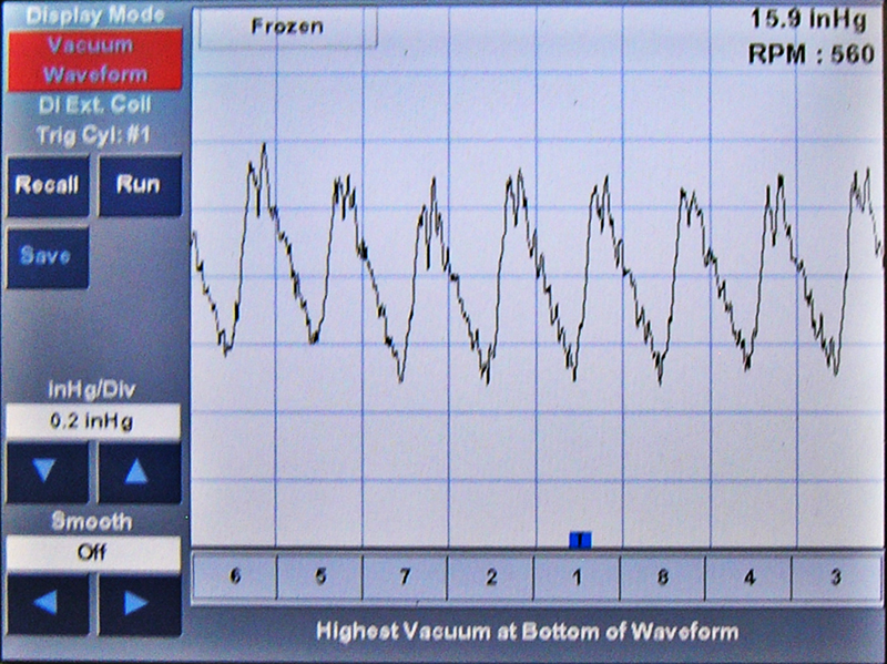
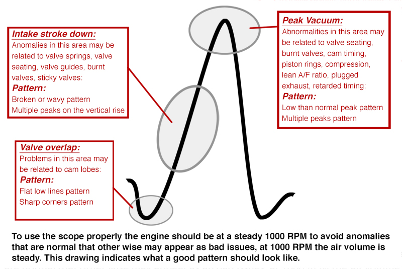
This digital vacuum waveform screen shot from a Bosch MTS5200 engine analyzer shows a normal vacuum signal waveform of a small-block Chevrolet V8.
The vacuum gauge air/fuel mixture tuning method could also be used the tune the cruise- and power-circuit air/fuel mixtures, but the mixture that will cause an engine to create the highest vacuum readings would be a richer setting that is better suited to allowing the engine to make maximum power than it would be for the best fuel mileage and lowest exhaust emissions. The best tool to determine what air/fuel mixture an engine wants is an exhaust gas analyzer because the readings can show the tuner the misfire rate, efficiency, and the air/fuel ratio the engine is burning. Another very valuable tool is a digital air/fuel meter, but the tuner will need to know what air/fuel mixture setting the engine needs for the various operating conditions at which it will most likely be driven.
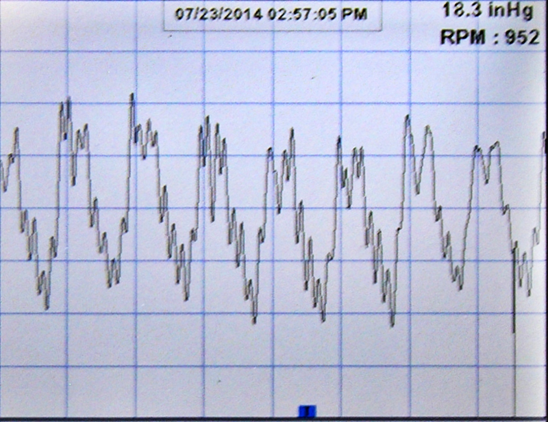
This screen shot shows that the vacuum signal the engine is producing has some anomalies. The readings indicate that the engine will need further diagnostic attention.
The vacuum produced at wide-open throttle at peak-power rpm can be used to determine if the air-flow/cfm rating of a carburetor is correct for the needs of an engine. A reading of one in. Hg under those conditions is the most common target. If it is higher, the carburetor may be too small and thus acting as a restriction to the engine’s demand. If it is lower than the target the carburetor may be too large causing the air speed through the venturis to be too slow, which can result in the air and fuel not being properly mixed into the vaporized charge that’s necessary for the engine to turn it into horsepower!
Vacuum diagnosis in the digital age
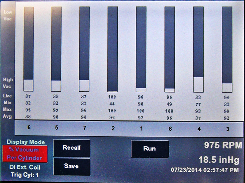
This display shows the percentage of vacuum each cylinder of the engine is producing. In this case, cylinder #2 is making very little vacuum.
The digital age has expanded the diagnostic information that’s available from the vacuum signal an engine produces. A technician can now use a modern lab scope with a vacuum module to observe the vacuum signal produced by each cylinder during cranking and while the engine is running. The vacuum waveform that’s displayed allows you to view the properties of the intake stroke of each cylinder and thus you will be able to get a look at the internal health of the engine.
The diagnostic tool we are using to observe these vacuum signals is the Bosch MTS5200 engine analyzer. The MTS5200 has both ignition scope and digital vacuum waveform functions so the user can perform vacuum, ignition, and cylinder balance tests on individual cylinders. The vacuum signal is synchronized to #1 cylinder so the vacuum waveform display will be listed by the cylinder, thus making it easier to diagnose which one is creating any problems.
The signal should be the same for each cylinder; therefore the waveforms should be almost identical. The display is a picture of each cylinder’s vacuum signal so it can identify the culprit, then you can use whatever means of diagnosis you choose to find out what the mechanical or sealing problem is.
Note: Even if a cylinder has no spark or the air/fuel mixture is not correct for the needs of the engine, it will still produce a “normal†vacuum signal.
Bad vacuum waveforms can be caused by poor piston ring sealing, improper valve opening due to worn camshaft lobes, damaged pushrods, improperly-adjusted rocker arms, poor valve sealing due to weak/damaged valve springs, sticky valves, burned valves, or an intake manifold vacuum leak. The hardest part of this diagnosis is identifying which cylinder is creating an irregular vacuum signal. Next, perform a compression test of the affected cylinder and look for vacuum leaks or mechanical problems that are causing the problem.
Modern diagnostic equipment such as the Bosch MTS5200 engine analyzer as well as the use of a traditional vacuum gauge can make it easier to diagnose mechanical problems with a vintage carburetor-equipped or even a modern fuel-injected engine so it can achieve its full potential power and driveability while avoiding the possible damage that can result from improper tuning.



0 Comments