For most of automotive history, the intake manifold was just an inactive lump of iron or aluminum. Not anymore.
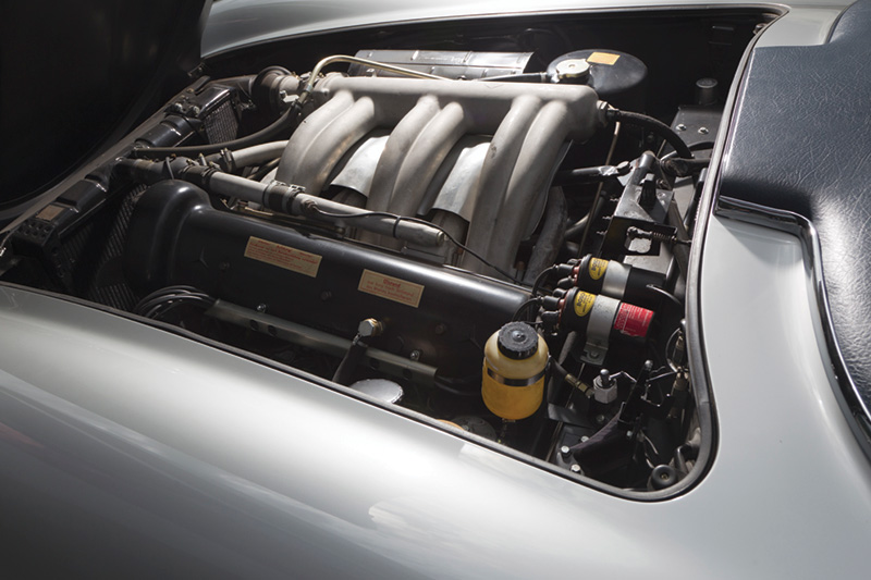
The runners of this 1952 300 SLS six prove that science was being applied by Mercedes-Benz engineers over six decades ago. The long runners enhance torque in the low- and mid-rpm ranges.
The history of the air intake manifold had been largely uneventful. For many decades, the design remained pretty much the same with sparse innovation. It was simply plumbing that made the air/fuel charge available to the combustion chambers willy-nilly with little thought devoted to how far each intake valve was from the typical centrally-located carburetor. The simplest way to understand this function is to think of the internal combustion engine as what it is: an air pump.
As an engine piston moves down on the intake stroke, a vacuum occurs the strength of which depends on atmospheric pressure at that time and location. In a carbureted or throttle-body injected engine, this atmospheric pressure forces the air/fuel mixture through the intake manifold and on into the combustion chamber through the intake ports in the cylinder head, which is burned and pumped out through the exhaust.
Traditional intake manifolds all follow the same basic design, usually consisting of four distinct parts: a mounting flange for an inlet control such as carburetor or throttle valve, a plenum to collect air volume, runners to direct air flow, and an additional mounting flange to couple with the cylinder head.
Saving weight
Early manifolds were simply steel or copper pipes, which were soon supplanted by highly-stable cast iron. To save weight, later versions were made of aluminum alloy. So, you won’t see cast iron intakes on newer engines, and even aluminum has been largely phased out. As manufacturing processes and materials evolved, composite plastic manifolds were developed. These offered an advantage beyond light weight in that they have better thermal properties. They can run much cooler than aluminum, improving air charge density, which can be blended with additional fuel to produce more power. In addition, plastics can be molded into more complex shapes than the sand casting of aluminum allows. This gives greater flexibility during the engineering process.
Magnesium alloy is another innovation that is becoming popular in certain applications. Magnesium parts have been around for maybe a century, but recent advances in high-pressure casting have made it a favorable material. The advantages of magnesium are its light weight along with strength and rigidity. Good thermal and acoustic properties are added benefits. Both composite plastic and magnesium manifolds are employed on today’s Mercedes-Benz vehicles.
Transitions
The move from carburetion to electronic fuel injection decades ago spurred changes in manifold design. This transition moved the industry away from “wet†manifolds that carried an air/fuel mixture on carbureted or throttle body injected engines. Port-type fuel injection brought us to a new age of “dry†manifolds that only flow the air involved in combustion.
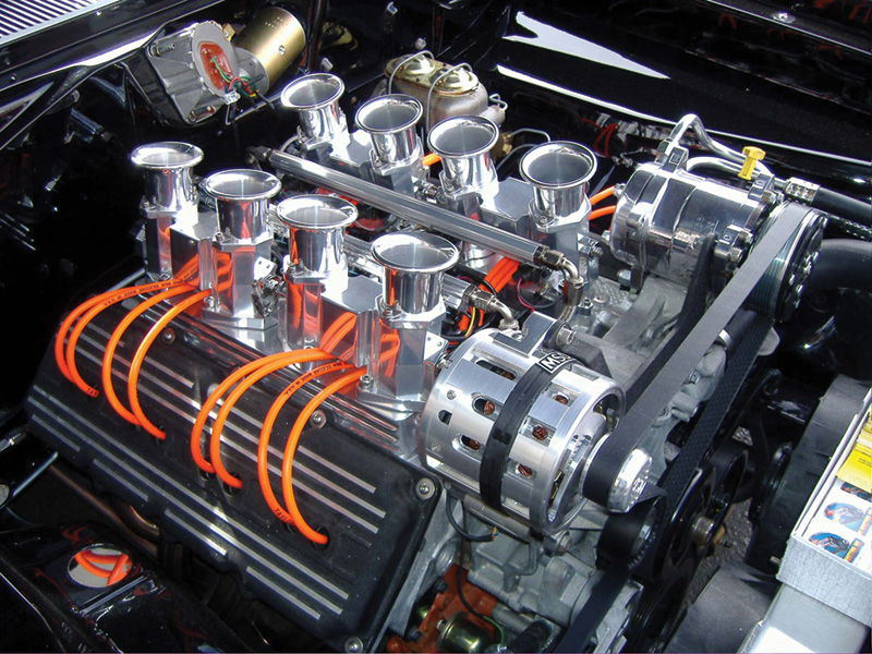
No, that’s not a Mercedes-Benz, but this domestic hot-rod engine serves to illustrate a point: Those intake runners are so short, this big V8 can’t generate enough power at low rpm “to pull your hat off,†as the saying goes.
Over the years, more and more attention has been given to “tuning†aspect of manifold design. In today’s world, demands for better fuel economy must coincide with demands for maintaining power. The intake manifold has become an integral part of the total engine design process rather than just an afterthought. Constant manifold refinement has added to the engine’s ability to produce more power, smoother operation, and vastly improved fuel mileage, and all with lighter, smaller displacement engines compared to those of years past.Â
The manifold comes alive
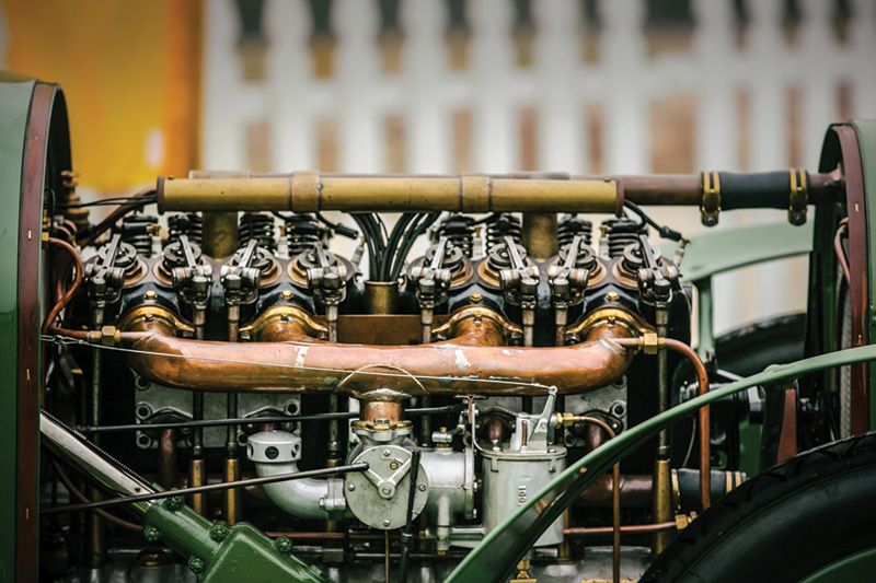
This early Daimler engine has as basic an intake manifold as possible. No tuning to a particular rpm, just copper plumbing.
Manifolds of the past were “fixed curve,†meaning they were designed to only accommodate a general balanced torque curve. In manifold design, plenum size, runner length, and shape are defining factors in how it performs. With a fixed design, the power band or fuel curve cannot easily be changed, so it is an exercise in compromise. It would tune reasonably well at all engine speeds, but excel at none.
In its quest for ever-increasing performance and efficiency, Mercedes-Benz introduced its first version of a two-stage manifold, or Variable Length Intake Manifold (VLIM), in 1994. Basically, VLIM technology allows for intake runners of two different lengths within the same manifold housing with controls that make it an “active†engine component rather than a passive one. This is accomplished by adding an internal flap that can open and shut depending engine speed.
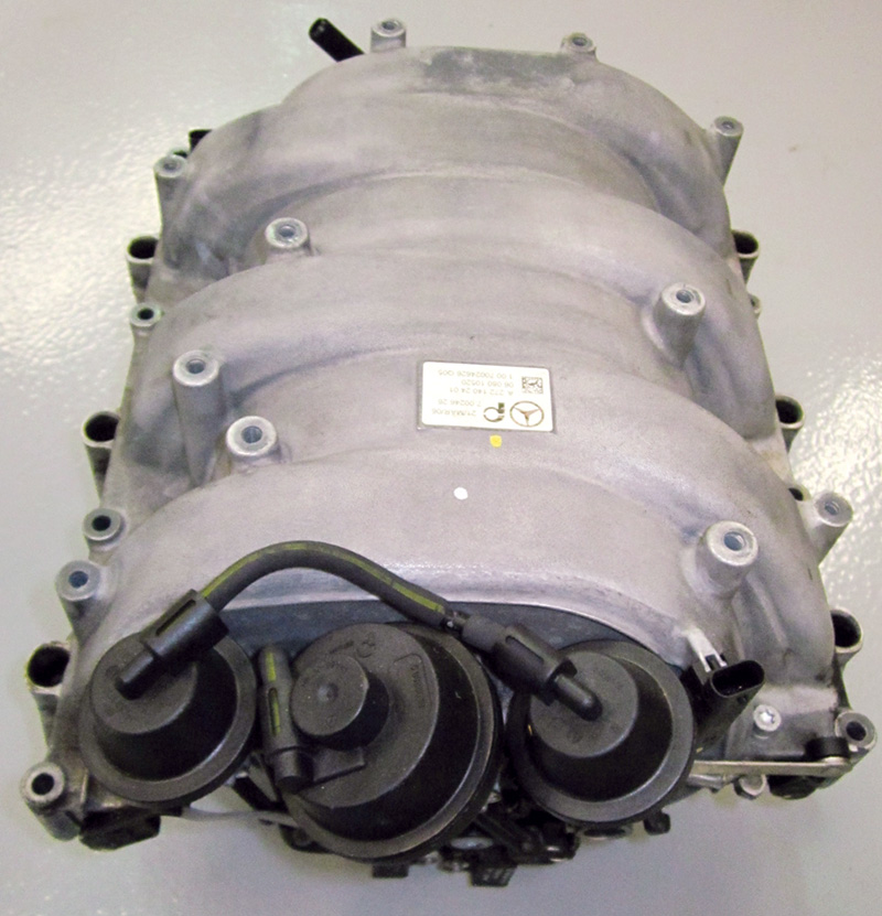
On this M272 intake manifold the vacuum actuator for the actuation of the tumble/swirl flaps is located between those for the variable runner flaps.
Why is varying the intake length a good thing? It optimizes horsepower, torque, and fuel efficiency by taking advantage of both the venturi effect and pressure waves known as “Helmholtz Resonance.†The ultimate goal of the design is to achieve 100% or better volumetric efficiency, which means having the cylinders fill to atmospheric (or greater) pressure as the compression stroke begins. At low speed and engine rpm, high vacuum exists, allowing for combustion chamber filling using the venturi effect. To fill the negative pressure in the chambers, air is sped up by shorter, slightly tapered intake runners. This increased air velocity allows for a more complete air charge.
As the throttle is opened and rpm and load increase, vacuum falls off, so resonance pressure waves are brought into play. When an intake valve shuts, the incoming air “slug†has momentum and is abruptly stopped. This causes a pressure wave to build up behind the closed valve inside the intake runner. By making the intake runner longer, this wave can be harnessed. Stacking the waves of air into the runner raises pressures and the amount of air for charging the cylinder, acting as a kind of low-pressure supercharge. This phenomenon only occurs in the narrow mid-rpm range. At higher revs and speed, dynamic pressure becomes key. This is the outside air being pushed into air inlets as vehicle speed increases. During this stage of operation, high rpm requires less fill time, so a short intake runner is desirable.
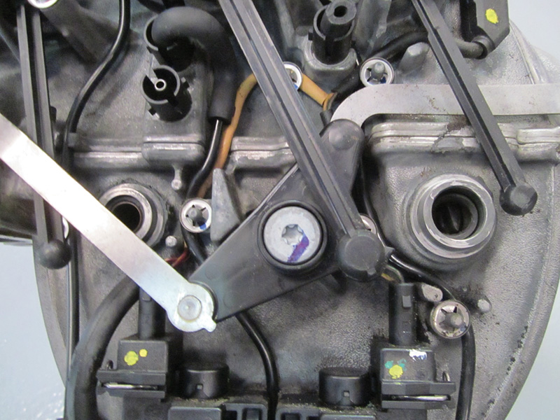
This M272 engine was neglected to the point that the flaps stuck and broke, as did the vacuum actuator rods. Plastic from the flaps was ingested into the cylinders, bending valves.
The mechanics of it
The Mercedes-Benz VLIM uses a spiral design with runners formed around the central internal plenum. This allows for longer intake runner length in a compact area. Each individual runner is typically about 800 mm in length. Individual runners are used to ensure that each cylinder has a sufficient supply of air flow without being affected by pressure waves created by other cylinders. Inside the manifold, resonance flaps were added to the runners. These are what allow the manifold to be variable. The flaps are located about halfway into the length of the runners. They are normally open, allowing air to take a shortcut from the plenum to the cylinder via a shorter runner path. Actuating the flaps closes the midway opening, forcing the air to take a path through the full length of the runner. Every runner has its own flap, but all are interconnected by shafts so that they actuate simultaneously.
Mercedes-Benz uses a vacuum actuator mounted on the manifold to actuate the variable flaps. At idle and low rpm, the internal resonance flaps are in the open position, held by pressure from a spring inside the aneroid. This is the short-runner mode, allowing incoming air to travel the shortest path to take advantage of the venturi effect. During midrange, approximately 1,700 to 3,900 rpm and under load of more than 50%, the flaps close for the long-runner mode. The power of engine vacuum is used in the aneroid to overcome the spring pressure and pull the flaps closed. The vacuum actuator receives vacuum from an internal supply reservoir located inside the manifold. This allows for the capsule to be cycled approximately five times before the reservoir replenishes itself via an internal check valve. Using a storage system ensures actuation during low-vacuum, midrange operation. Vacuum to the capsule is controlled by an electric solenoid valve. Mounted on the manifold, the valve is triggered by the engine management computer when conditions are right.
Continued refinement
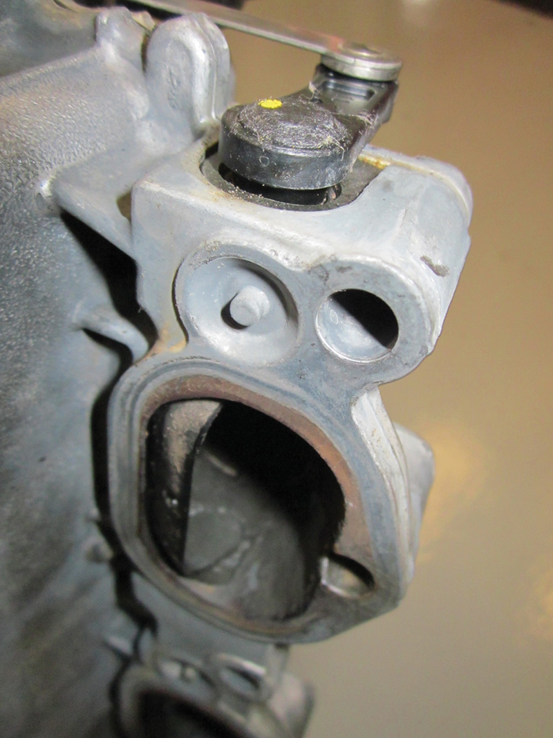
The tumble/swirl flaps are located directly upstream of the manifold runner/cylinder head intake port interface.
The latest innovation in manifold technology came when Mercedes-Benz introduced the M272/273 engines. Tumble flaps were added to the manifold outlets. These flaps are swung into the intake ports just ahead of the fuel injectors. By partially closing the port, the curved shape of the tumble flaps causes the air charge to speed up and swirl. This helps to blend the mixture for a more homogenous charge. These flaps are actuated by means of a vacuum actuator similar to the one for the resonance flaps, and are held in the recess position by spring pressure until they are vacuum-actuated by engine management at 50% load. Sensors at the end of the tumble flap shaft are used to monitor position. In the event that a flap does not fully open, or fails to open at all, a fault code will be set.Â
Moving parts can fail
Taking intake manifolds from a completely static component to one with mechanical motion brings a new set of concerns. Older fixed manifolds were almost completely problem-free other than the warpage of aluminum units on inline engines that caused vacuum leaks at the manifold/cylinder head seam. Adding moving parts both internally and externally makes proper maintenance more critical than ever before. Because the internal flaps, pivot bushings, and seals are exposed inside the manifold, anything flowing there has the potential to cause damage. This should lead us to look at emissions controls that also make use of the intake manifold. First is the exhaust gas recirculation (EGR) system. EGR takes a little spent exhaust gas and returns it to the intake manifold. This process under light engine load dilutes the air/fuel charge to help keep oxides of nitrogen (NOx) from forming during combustion. The potential hazard that arises is coking. Coke is the sticky tar-like substance that can form due to incomplete burning of carbon during the combustion process, and this flows through the intake manifold during EGR operation. The unburned carbon combines with moisture in the incoming air to become this sticky film. Over time, these deposits build up and coat the flaps. If enough coking exists, eventually it can cause part failure. Failure comes in the form of sticking or broken flaps, and premature bushing/seal failure. Symptoms could range from misfires, vacuum leaks, loss of power, to, worst case, broken parts that become free and are ingested into the cylinders causing valve or piston damage.
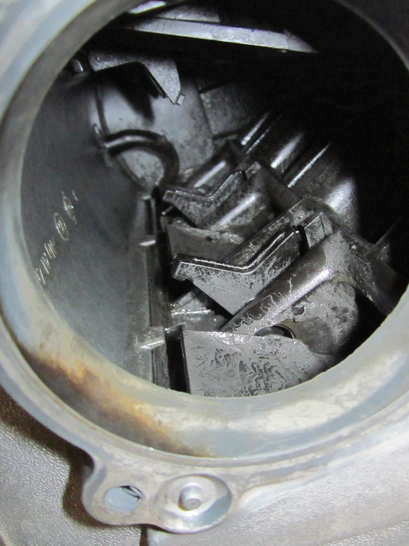
Looking inside this manifold, you can see the coked-up variable flaps, and also the vacuum line at the back coming from the internal reservoir.
Another system for concern is positive crankcase ventilation (PCV). Crankcase pressure build-up is also routed through the intake manifold. This process poses the same coking hazards as EGR, only in this case the carbon comes in the form of oil vapor.
To prevent or minimize these hazards, proper Mercedes-Benz maintenance is highly encouraged. The right fuel grade (“Top Tierâ€), and recommended air filter and spark plug service intervals optimize combustion, decreasing coking from EGR carbon. Factory-recommended oil and weight at correct mileage or time change interval will reduce coking from oil vapors. Intake tract cleaning has become a popular service, but that will be the subject of a future StarTuned article.
So, once again, recommending good maintenance services to your customers will likely save them from having to pay for expensive repairs.Â


0 Comments