
VW exhaust valves have a split personality
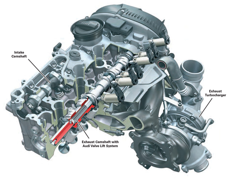
In the mid-2000s, Volkswagen introduced a 2.0L version of its 1.8L SOHC EA 888 engine family. This new turbocharged fuel-injected gasoline engine incorporated many of the features that had proven successful and reliable in its previous iteration, with a dual overhead cam/4-valve design, and was identified as CCTA/CBFA. Subsequent engineering led to innovative new technology for exhaust valve actuation that actually provided an exhaust camshaft with dual lobes for each valve and a sophisticated switching mechanism to alternate valve operation between two modes. This new configuration became known as the CBEA family of engines.
The dual-function exhaust valve activation allows for differing engine performance characteristics depending on demands and operating parameters, such as throttle position and other inputs as determined by various sensors and the vehicle’s Motronic Electronic Control Unit (ECU). At low engine speeds, when demand for power is modest, a narrow profile cam lobe contour manages exhaust valve timing. In particular, it provides for very late valve opening, such that the exhaust pulse cannot back-flow into the cylinder during the valve overlap phase of the combustion cycle.
At the same time, under light loads, this dual-valve technology allows the intake cam to be designed in such a way that the intake valves open sooner than they would otherwise. This provides two benefits: Advanced valve timing tends to move the engine’s torque curve downward, enhancing low-speed driveability and acceleration. At the same time, the earlier ingestion of the intake charge, combined with the delayed exhaust valve opening, generates a more positive charge in the cylinder, reducing the volume of spent exhaust gases remaining in the combustion chamber and retaining more of the intake charge in the cylinder at lower engine speeds.
What are the benefits?
Specific benefits of this technology include improved throttle response and higher torque at low rpm, making the torque curve steeper, and reducing turbo lag at lower engine speeds.
Conversely, at higher engine speeds, the engine switches to an alternate exhaust camshaft lobe profile that allows for more efficient combustion and enhanced fuel economy, with correspondingly lower exhaust emissions.
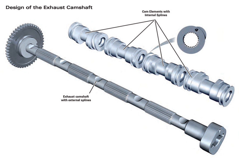
The dual operation of the exhaust camshaft function is an ingenious design, using separate exhaust cam “elements,†one for each cylinder (remember, that as a DOHC engine, there is a separate intake cam that is unaffected by the dual exhaust cam lobe function). Each of these four exhaust cam elements is mounted on a common splined exhaust camshaft. Each of the four exhaust cam elements contains two lobes for each of two exhaust valves, such that the four exhaust cam elements contain a total of sixteen lobes, sufficient to provide dual function to each of the eight exhaust valves.
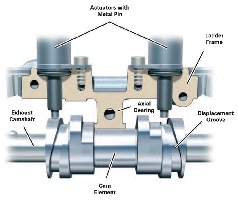
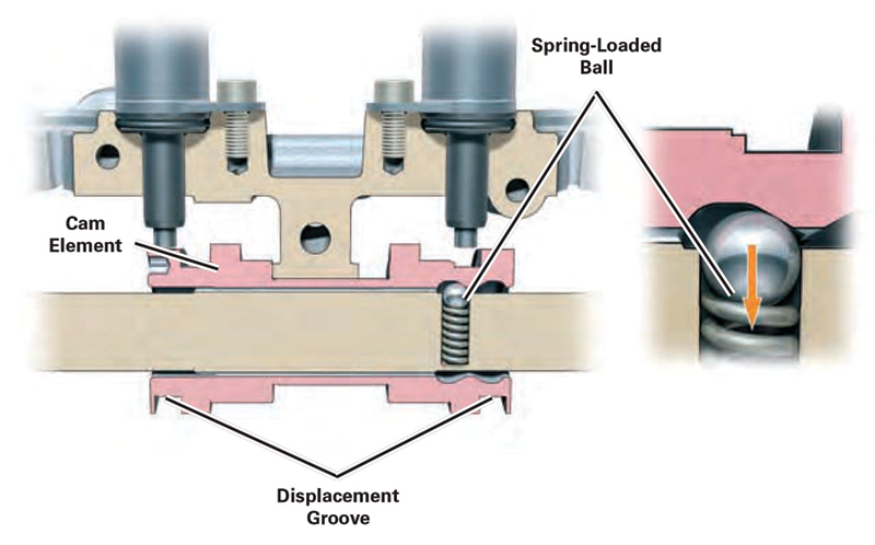
In operation, when various conditions are met, the selection of a particular exhaust cam lobe is performed by electro-mechanical solenoids that move the exhaust cam elements side-to-side, depending on the mode selected. There are two solenoids for each of the four cam elements — one solenoid selects the large cam lobe, and the other solenoid selects the small cam lobe. A spring-loaded metal detent pin helps hold the element in the appropriate position.
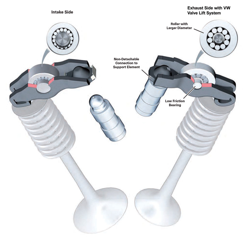
Since it is the camshaft elements that move side-to-side courtesy of the solenoids, the rocker arms with their roller followers remain in a fixed position. A helical groove in the elements helps allow for a smooth transition from one lobe to its mate.
In operation, when the engine is first started, the Motronic engine management system directs the solenoids to select the larger exhaust lobes for easier startup. Immediately after the engine starts, the system changes over to the smaller lobes. Under most driving conditions, the system will retain the use of the smaller lobes up to about 3,100 rpm. Upon shut-down, the system reverts back to the larger cam lobes in preparation for the next start-up.
Service considerations
In the nearly ten years this system has been in service, it has proved to be both durable and reliable. Yet there are some items that technicians need to be aware of. The solenoids that activate the elements can, upon occasion, fail. When they do, a Check Engine light will help alert the driver to a problem, and a Diagnostic Trouble Code (DTC) will advise the technician as to which solenoid requires attention. Once the plastic engine cover is removed, the solenoids are readily visible, and are easily replaced after removal of a single Torx® fastener and electrical connector.
Similarly, the vehicle is equipped with camshaft rotation sensors, which have also been known to develop trouble. Again, a Check Engine light and DTC will direct the servicing technician to the appropriate sensor. Less likely is a problem in the cam phaser system, but this too will be identified with the appropriate DTC.
Maintenance is especially critical
Because of the precision of this dual-lobe system, and the speed with which it must respond in order to help optimize engine performance and emissions control, it is especially critical that maintenance be performed at least as often as recommended. Due to the tight tolerances of the various components in this system, you can make a strong case for owners to schedule oil changes and other routine maintenance at the intervals spelled out in owners’ manuals or electronic service reminders. Be certain to use engine oil precisely as specified for this engine family, available, of course, from your local VW parts department.
Any sludge or carbon build-up in these engines can adversely affect the performance of this sophisticated dual-valve function. This debris can cause binding or galling of the splines on the exhaust camshafts and elements, they can interfere with the proper operation of the detent balls and springs, and, of course, they can cause wear on the camshaft lobes and followers. Wear or damage on the lobes of the camshaft elements will be evidenced by an engine misfire DTC, which will direct you to the errant element and lobe.
What about the cylinder head?
With proper maintenance, cylinder head service is not required on this engine family any more than on other modern-day engines. The cylinder head gasket is a robust MLS (Multi-Layer Steel) design, and holds up well. However, with these engines, as with all engines with aluminum cylinder heads, overheating can quickly cause a cylinder head to warp and the head gasket to fail.
If removal of the cylinder head is called for, you must exercise various cautions — some typical of cylinder heads from other engine families, and some specific to this engine design. For example, you should perform appropriate diagnosis before beginning any disassembly. Most likely a cylinder leak-down test coupled with DTCs that are displayed will point you to the particular problem area.
You’ll want to set the engine at TDC before beginning disassembly, and be sure to take special note of markings on timing gears/sprockets, including corresponding markings on the cylinder heads, and also markings for direction of rotation, since these steps will help you greatly during reassembly. Like most sophisticated engine designs, this engine family is an interference design, so you’ll want to be certain not to rotate the crankshaft if the cylinder head is on and the timing chain is not in place.
Special cautions
You’ll probably not be surprised to learn that the cylinder head bolts on these engines are of the Torque-To-Yield (TTY) type, which means they can only be used once and then must be discarded and replaced with new. These head bolts are not included in VW head gasket sets, and must be purchased separately.
You may be surprised to know, however, that many of the other fasteners on these engines are also TTY bolts, and cannot be re-used. Such bolts are used in various places around the engine, and also for mounting of the turbocharger. As such, the parts professional at your local Volkswagen parts department can be your best friend here, and can help identify those fasteners that must be replaced every time.
Another note of caution: Any cylinder head service will likely call for disconnecting the fuel rail from the fuel injectors. Any time the fuel system is open there is the potential for debris to enter the system. Since modern fuel injection systems work within extraordinarily close tolerances, the introduction of any debris into the system holds the potential for compromised performance and/or component damage. So, be especially careful to plug any openings in the fuel system when performing cylinder head or related services.
Timing chain tactics
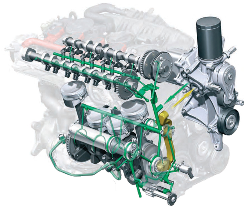
These engines use chain-driven camshafts, so no routine replacement of fibrous timing belts is required. If you do encounter one of these engines with substantial sludge build-up, however, it is likely that the timing chain will also warrant replacement. These timing chains ride on guide rails, and if the chain is worn, then the guide rails are likely due for replacement as well. Furthermore, these engines use a hydraulic timing chain tensioner behind the guide rails, and if the chain is badly worn, it is possible that the free play in the chain exceeds the ability of the tensioner to compensate for that wear. This would be evidenced by timing chain rattle, which, sadly, is a sound that many technicians are familiar with.
Timing chain replacement on these engines is not a simple task. In addition to removal of the cylinder head, the process will also require removal of the harmonic balancer, the timing cover, and other components that restrict access to the front of the engine.
Finally, though it may be routine, and you should make it so if it is not, you should be certain to chase all threads before reassembly, and also to remove any oil or other debris or liquid from tapped holes in the block, head, and elsewhere. It is entirely possible that torquing a fastener into an obstructed hole can generate enough mechanical or hydrostatic force to crack and destroy the component the bolt is being threaded into. It’s a simple step, easily overlooked, but a critically important one.


0 Comments