Not that many years ago, the advanced safety systems found on Mercedes-Benz vehicles would’ve been considered science fiction, and there’s no question that they’ve helped prevent thousands of accidents. So, you sure don’t want to compromise their functionality during collision repair.
For decades, automotive safety has been about making the strongest, most energy-absorbing protective bubble possible. Today, Mercedes-Benz is transforming the bubble into a truly interactive driving partner. The new Mercedes-Benz evolution — and we have to call it that because it is constantly innovating and improving — provides not only advanced structural support to maximize collision survival odds, but also a wide variety of state-of-the art accident avoidance technologies.
The Mercedes-Benz accident avoidance strategy combines four high-tech safety elements: risk monitoring, driver alerts, interactive driver assistance, and, if necessary, autonomous steering, speed control, and braking. The focus is to either keep drivers from getting into an accident in the first place, or to significantly reduce the severity of an unavoidable collision.
Mercedes-Benz has engineered an impressive amount of cutting-edge sensor technology, including multiple camera, radar, and ultrasonic devices to monitor and assess risk in the environment 360 degrees around, including in front and behind the vehicle. There is technology that can sense if a vehicle or obstacle, including a pedestrian, is too close for your current driving speed and direction. Immediately upon detection, in-vehicle systems alert the driver to any potential danger, including lane change, cross traffic, blind spot, backup, and, of course, frontal collision risk.
Monitoring also includes making sure that the driver is paying attention to the road. If he or she does not respond to the visual and audio warnings provided by the safety systems, the more advanced systems can automatically initiate collision avoidance maneuvers without waiting for driver input.
Radar-based systems
The DISTRONIC (DTR)/DISTRONIC PLUS systems regulate speed and distance from the vehicle ahead. The distance is measured in the amount of time in seconds it would take at the intended speed to reach and impact the vehicle ahead. The driver sets the desired speed and distance using the cruise control lever.
DTR systems are managed by the video and radar sensor system control unit. The control unit reviews input from the long- and short-range radar sensors, then initiates braking and adjusts engine speed as needed to meet the speed and distance targets set in cruise control.
Correct body alignment is critical for proper function of radar-based safety systems. If panels on which short range radar sensors are mounted are misaligned, it can negatively affect what they see. For example, even small deviations from the proper angle when a short range sensor is mounted on the inside of the bumper can create large errors in the observation of the road ahead.
Radar system function is also sensitive to suspension alignment. An incorrect rear thrust angle is likely to cause rear or front radar to scan off target. If the thrust angle is off enough, long range radar may actually scan the wrong traffic lane.
Check radar vision after repairs
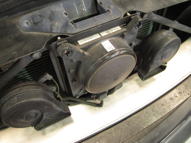
After any front collision or suspension repairs, the Distronic sensor must be adjusted using a Mercedes-Benz headlight aiming system to determine where to place spacers and how much to tighten each individual mounting adjustment bolt at the four corners of the sensor mounting frame.
If there has been damage to the DTR radar sensor, or any alteration of the camber, caster, track width, or vehicle level, you must adjust the DTR radar sensor after the repair. Check and correct ride height using a Romess gauge for height and inclination angle measurement and Diagnostic Assistance Software (DAS), or, for 2011 and newer model year vehicles, XENTRY (see sidebar for more about XENTRY). Perform an initial start-up and aiming of the Short Range Radar Sensor after replacement of the sensor or of the Radar Control Unit, and after any front or rear bumper repairs. Use XENTRY or DAS to confirm Short Range Radar accuracy.
Initialize the DTR Control Unit
Don’t forget the DISTRONIC control unit. Because it receives inputs from a wide variety of vehicle systems, many different repairs require as a final step initialization of the DTR control unit. Initialization of the unit requires the use of XENTRY.
System operating inputs include engine and drivetrain operating condition, engaged gear range, parking brake status, engine drive torque/brake torque, and yaw, lateral, and longitudinal acceleration information, all sent over the chassis CAN to the DTR control unit. After any repair that includes disconnecting chassis components, technicians must initialize the DTR control unit.
Accurate collection and assessment of steering inputs requires initialization of the DTR control unit after removal of the steering wheel, replacement of the steering angle sensor (SAS), or installing new yaw, lateral, or longitudinal sensors. Driver inputs through cruise control are sent to the DTR control unit by the steering column tube module, which, if replaced, also requires DTR control unit initialization.
If repairs included wheel alignment, or, of course, replacement of the DTR control unit, you’ll need to initialize the DTR control unit.
PRE-SAFE Brake and BRAKE ASSIST PLUS
PRE-SAFE Brake is part of the DISTRONIC PLUS system. Once DISTRONIC PLUS detects an unsafe following distance or speed, the system provides the driver with both visual and audio warnings. If the driver does not react quickly and with the appropriate braking effort, PRE-SAFE Brake activates the Brake Assist System (BAS) PLUS, which begins independently applying a light braking force. If light braking is not adequate to resolve any impending collision risk, BAS PLUS applies emergency brake pressure.
Blind Spot Assist/Active Blind Spot Assist
The Blind Spot Assist system monitors the rear and side areas of the vehicle using short range radar sensors mounted in the rear and front bumpers. Blind Spot Assist alerts the driver of any risk of impending collision with vehicles in the blind spot via visual and audible warnings. Active Blind Spot Assist adds the ability to initiate braking without input from the driver. Given the vehicle weight and momentum, braking force applied to selected wheels alters the vehicle direction away from the blind spot area in which there is another vehicle, thus reducing the risk of a collision.
PRE-SAFE Brake and Blind Spot Assist each rely on short- and long-range radar technology, as do the DISTRONIC/DISTRONIC PLUS systems. As such, each are subject to the same radar check and adjustment requirements as the DISTRONIC family of safety systems.
Parking Assist Systems
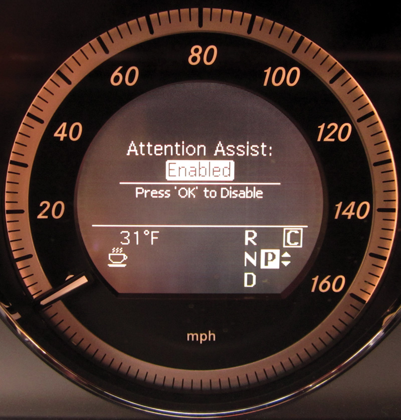
Attention Assist assesses driver fatigue by monitoring the steering angle sensor (SAS). An algorithm assesses the frequency of change (or lack thereof) in steering direction, acceleration, and other indicators of driver activity level. It warns the driver using audio and haptic (vibration of the steering wheel) signals when the software determines that inattentiveness may have reached a dangerous level. The steering column tube module and SAS form one component and can only be replaced together if damaged. After replacing the steering column tube module you must initialize the Distronic control unit.
The Parktronic system assists drivers making parking maneuvers. The system uses ultrasonic sensors and short range radar to measure the distance between the vehicle and objects near its front and rear bumpers.
Parktronic short-range radar sensors are mounted behind, and must be able to “see†through, the bumper. When filling or painting bumpers in the area of the sensors, do not exceed a coat thickness equal to approximately two coats of paint. Even though they may not be mounted behind a bumper or other component, the same two-coat limit applies when painting ultrasonic sensors. Use the two-coat guideline when repairing any Mercedes-Benz models with Parktronic, Park Assist, DISTRONIC PLUS, and Blind Spot Assist technologies.
Test radar-based and ultrasonic systems after repair, noting whether or not you can see all relevant forward, rear, and corner (side angle) views. If a sensor does not function after painting, and removing the paint and re-coating is not likely to solve the problem, replace the sensor or bumper in which it is embedded.
Camera-dependent Safety Systems
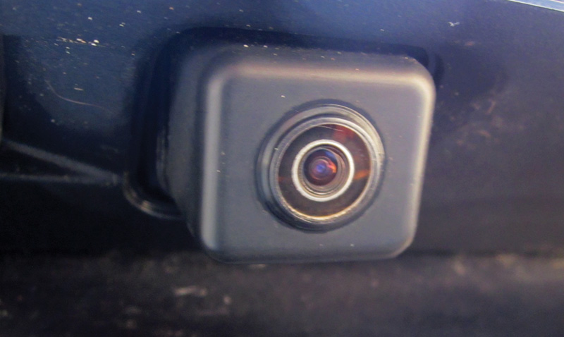
Sometimes it’s the simple things. A complaint about a hazy rear-view screen in the dash on this 2010 E 350 turns out to have been due to the backup camera location. The owner missed cleaning the camera lens at car wash time due to the rear deck lid overhang. A little glass cleaner, and a suggestion to the owner to remember the backup camera when washing the car, and everyone was happy.
Lane Keeping Assist, Active Lane Keeping Assist, Night Vision, and Backup Camera systems each use multi-function cameras to provide visual data about where the vehicle is relative to road markings, nearby traffic, and other potential collision risk factors. Steering angle and radar sensor data is combined with the camera-provided images to give a reliable assessment of vehicle location at any point in time.
Lane Keeping Assist constantly scans the road ahead and provides images of lane markings to add to the radar data about traffic volume and flow. It warns the driver when the vehicle is about to cross into another lane. If the driver does not respond to the warnings, and the vehicle is equipped with Active Lane Keeping Assist, the active system initiates braking action to shift the vehicle direction back between its original lane markings. The camera data is fed into the radar sensor control unit, which, after checking radar inputs to confirm that the vehicle is drifting too close to traffic in another lane, makes minor steering adjustments to help bring the vehicle back inside its original lane markings.
The backup cameras provide visual guidelines that show the driver where the rear of the vehicle is pointed and which way and how much it needs to turn to fit into a parking space. The space can be defined by traditional parking lot markings on the ground, or by the proximity of nearby vehicles. The visual guidelines provided by the backup camera change as the steering angle changes.
All cameras must be recalibrated using XENTRY Connect if the control unit, camera, or cable connecting the two is replaced, or if the component on which the camera is mounted (windshield, trunk lid, etc.) is replaced. A calibration fixture, laser and target are also required for backup camera calibration. A headlight aimer and target are required for calibration of the Night Vision Camera. See WIS for complete headlight aiming and other calibration procedures.
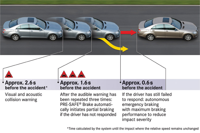
PRE-SAFE Brake assesses risk and takes collision avoidance action in milliseconds, if necessary. However, collision repair must restore the correct body alignment. Any misalignment will cause sensors to “see†somewhat off-target. Radar sensors in the bumpers must be mounted at the exact factory-recommended angle, thrust angle and ride height must meet specifications, and body panels must be within tolerances at all attachment points.
XENTRY – Trial Run Recalibrations
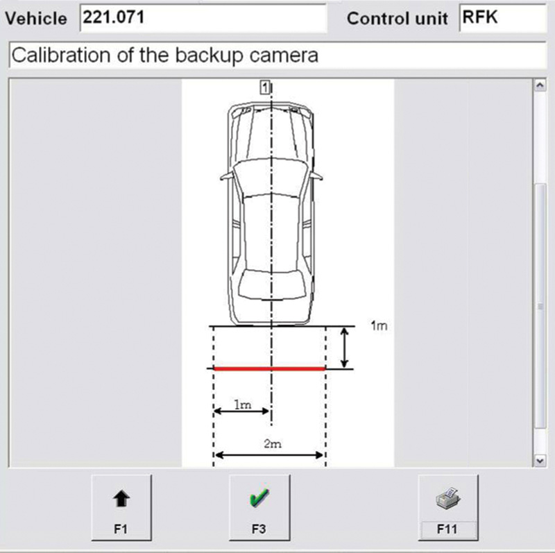
The Backup Camera must be installed perpendicular to the vehicle centerline, centered horizontally, and calibrated with targets showing precise distances from the rear of the vehicle.
The Mercedes-Benz Star Diagnosis System (SDS) combines a compact, portable computer, access to OBD and other vehicle systems performance data, and XENTRY — the latest Mercedes-Benz diagnostic software. The hardware and software together help you check vehicle systems for possible causes of error codes and performance problems.
You all know how frustrating it is if you miss a step in a diagnostic trouble tree, hardware initialization sequence, code reset, program re-flash, or component calibration process. XENTRY allows you to go through a simulation of the sequence of steps in a test, diagnostic process, or hardware initialization/recalibration. You learn what codes and inputs are needed, the proper order in which to perform certain steps, when it is ok to key-off or disconnect a device, etc., without risk of losing data or damaging a component.
Check and adjust the aim of the Long Range Radar Sensor if any repairs that could affect the position of the sensor have been made. This includes front collision repairs, wheel alignment, and, of course, long-range radar sensor replacement. A special Mercedes-Benz laser tool is required.
The long-range radar sensor can only be aimed on the MKS alignment rack. The MKS system is recertified every six months to ensure that the rack is level and the heads are calibrated to a max tolerance of ± 1 mm. Check your MKS rack daily for accuracy. Remember, correct long-range radar vision is a critical safety feature.Â


0 Comments