This state-of-the-art system has been around for a while. You should know how it works. Today’s technician also needs to know how this system integrates into the big picture of engine management. Let’s also look in to the need for proper connections in this system.

Many of us technicians were shocked when we first heard of the concept of throttle-by-wire (or, drive-by-wire). What, no positive, mechanical connection between the driver’s right foot and the throttle blade? No traditional and completely-safe control of engine acceleration? Whew.
Believe it or not, electronically-controlled, electric motor-powered throttles first appeared in Volkswagens with the adoption of Robert Bosch Motronic ME 7 engine management back in 1999 for the 2.8L VR-6 engine, then in 2000 for the 2.8L 5V V6 and the 1.8L 5V turbo. In all the years since, it hasn’t actually been the big technical nightmare you might have expected it to be, and to our knowledge no accidents because of it have ever been reported.
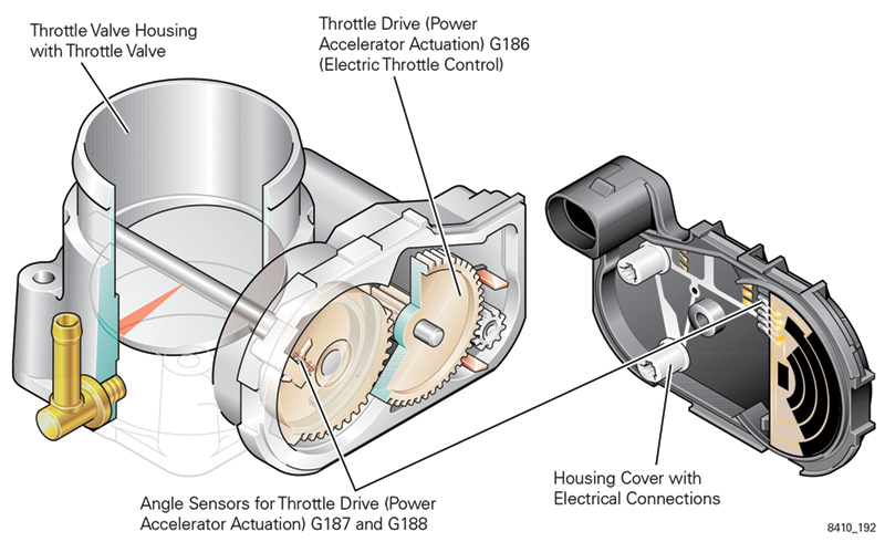
Basically, an electric motor rotates the throttle valve shaft through a set of reduction gears according to computer commands. Benefits over a simple cable? More than you might think. Not only does it maximize engine torque and efficiency by keeping the velocity of the intake stream and manifold vacuum at higher levels than a human could ever do, it also allows cruise control without the necessity of adding a big vacuum actuator and attendant hardware.
Extreme safety measures have been designed into both the hardware and the software. Two position sensors are used for continual self-checking of signal plausibility. A safety module is integrated into the ECM to monitor the functional processor for proper operation.
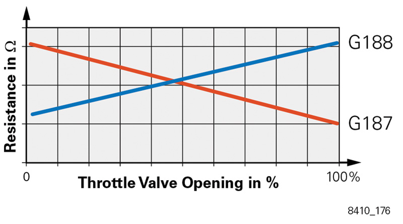
One of the clever features of the design is that the two Throttle Drive Angle Sensors (G187 and G188) are opposite in resistance, and are used for continuous cross-checking by the ECM. The sensors are provided with a 5V reference voltage, then the ECM reads the voltage drop across these variable resistors and uses this to monitor throttle valve angle. The assembly including the throttle drive mechanism is designated G186. In later models, throttle-by-wire is integrated into the K132 Electronic Power Control (EPC) system.
An Aside on ME 7
Motronic ME 7, by the way, was the first torque-based system and also the first to consolidate processing of all subsystems in a sub-processor responsible for engine performance functions. Earlier systems used separate sub-processors for such things as ignition, fuel, or emissions controls.
It also allowed cruise control to be integrated into the ECM, which is given the authority to hold and change the throttle valve angle as the previously-used vacuum pump did with much less intelligence. This allows for a more accurate transition of throttling as well as a more stable speed. Similar to M5.9.2 systems, the Brake Pedal Switch (F47) and Brake Light Switch (F) are combined in a single housing. One side controls normal brake light function, and the other lets the ECM know that the brakes are being applied so it can disengage cruise.
Motronic ME 7 brought about several changes in, and additions to, components for both engine management and other related functions. Besides Electronic Throttle and cruise control, these include:
- Charge Air Pressure Sensor (G31)
- Integration of the Barometric Pressure (BARO) Sensor (F96) as a component of the Engine Control Module (ECM, J220)
- Turbocharger Recirculating Valve (N249) — Using an electrically-operated solenoid valve to manage activation of the bypass valve allows for more accurate control of charge pressure bypass during throttle changes (refer to Self-Study Program 892303).
- Dual stage intake manifold with an ECM-actuated Intake Manifold Tuning (IMT) valve (N156)
- Dual ECMs (W12 only)
- For more information on ME 7, refer to SSP 842003.
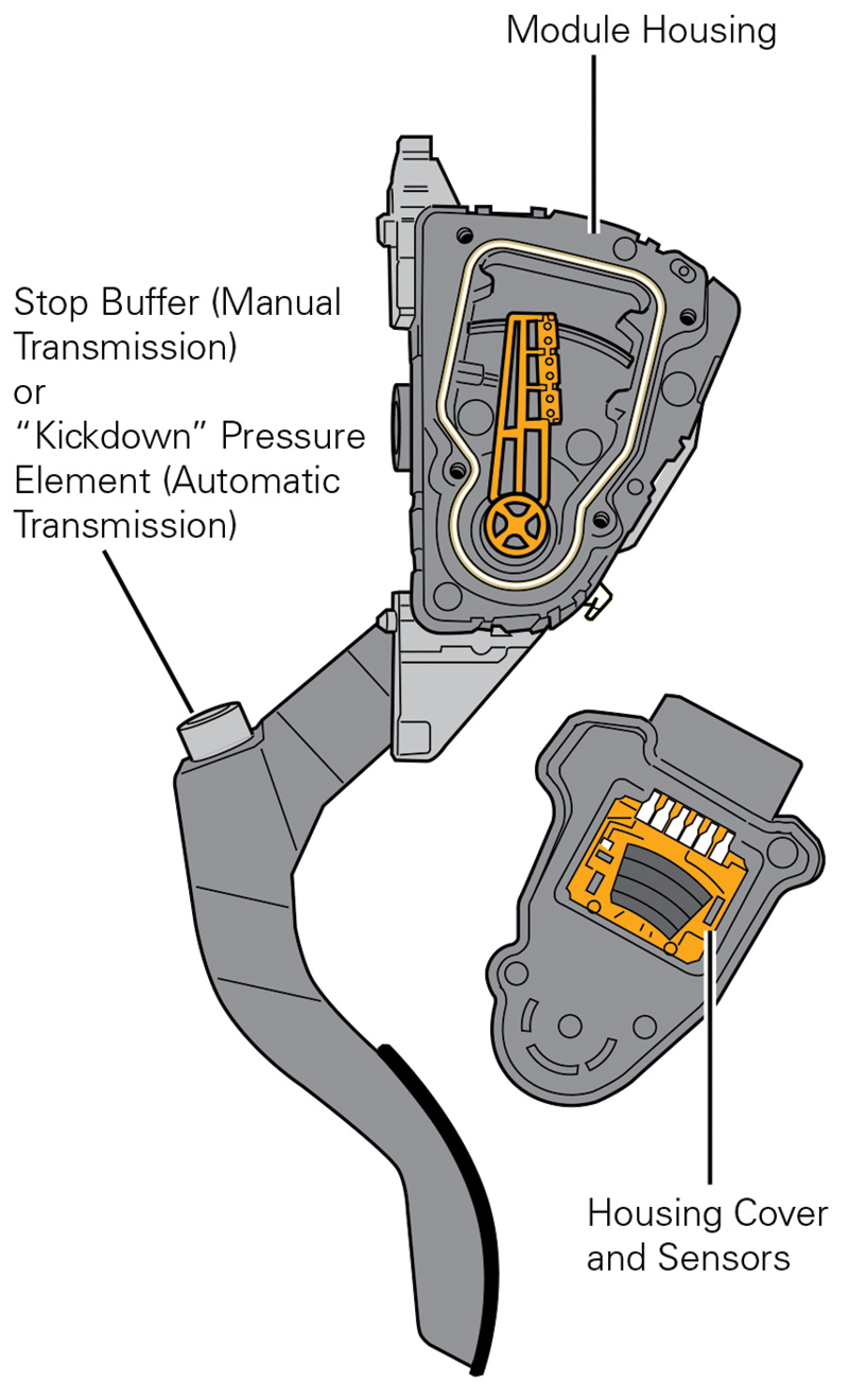
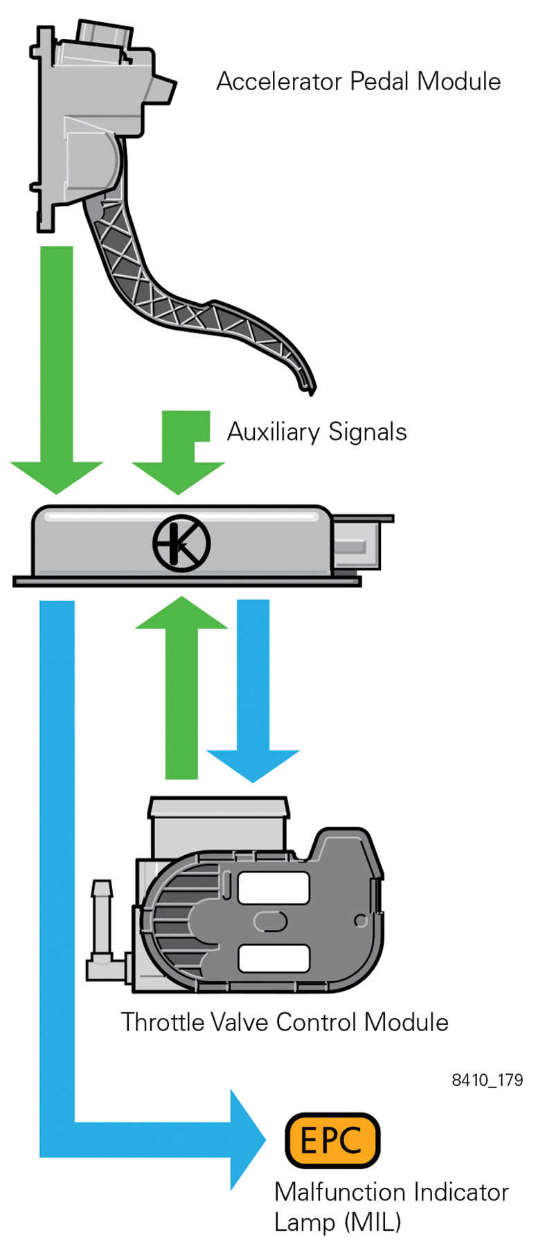
Pedal Module
The accelerator pedal module combines the accelerator pedal and the accelerator position sensors into one assembly. The electronic components of the pedal module are:
- Throttle Position (TP) Sensor (G79)
- TP Sensor (G185)
The redundant throttle position sensors are linear to each other on different scales. Like the dual throttle drive sensors, the duplicate sensors are for self-diagnosis. They also provide an analog signal to the ECM referencing accelerator position, and the kickdown function is incorporated into the module. If the driver activates the kickdown, the full-throttle voltage of the accelerator pedal position senders is exceeded. The ECM interprets this as a kickdown and sends a signal the Transmission Control Module (TCM) by way of the CAN data bus.
If one of the TP sensors fails, the ECM relies on its companion sensor for redundancy. If both TP sensors fail, an Emergency Running Mode is initiated — fast idle, but no throttle response.
Warning!
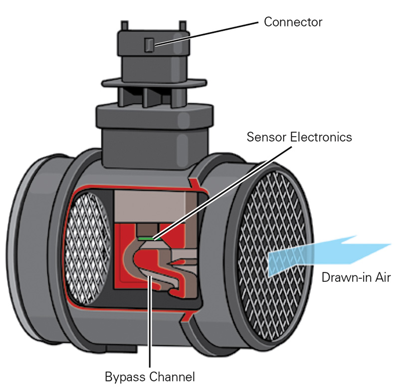
In addition to the universal OBD II MIL (Malfunction Indicator Lamp), a separate fault indicator light (K132) is used for EPC. Malfunctions in either the electronic accelerator system or associated sensors are detected by the self diagnostics, and are indicated by the separate EPC warning light. For example, a fault in the Mass Air Flow (MAF) sensor (G70) signal triggers the EPC warning because the ECM uses it for input on engine load. The computer also references this signal to check the plausibility of other inputs. When a problem is detected, an entry is made in the fault memory. The ECM is able to recognize range/performance faults, as well as signal range checks for the angle sensors. The G186 is monitored for range of operation and idle adaptation faults.
When the ignition is switched on, K132 is illuminated for three seconds. If no faults have been detected, it goes out. K132 is activated by the ECM, which turns it on by providing ground.
From the Field
With this system having been in use for so long and on so many models, some problem patterns have naturally shown up. The most obvious, of course, would be the illumination of the EPC “Fault Light†on the dash, typically located in the tachometer face. As already mentioned, when malfunctions in either the electronic accelerator system itself, or associated sensors or wiring, are detected by the self-diagnostics, they are indicated by the illumination of this separate warning light, and an entry is made in the fault memory.
Reports from techs in the real-world trenches of auto repair indicate that other symptoms sometimes appear, often in confusing combinations and especially on early models. For example, you may encounter a specimen wherein engine rpm does not respond to pressure on the accelerator and stays at a fast-idle speed (although very high revving has also been mentioned). A likely cause of this condition is that the ECM has initiated an “Emergency Running Mode†(sometimes called “Limp-Inâ€) and is only allowing very limited vehicle operation with a high-enough idle speed to allow some forward progress, but nothing like normal highway speed. There is no substitute function for the throttle drive that can take over when this happens.
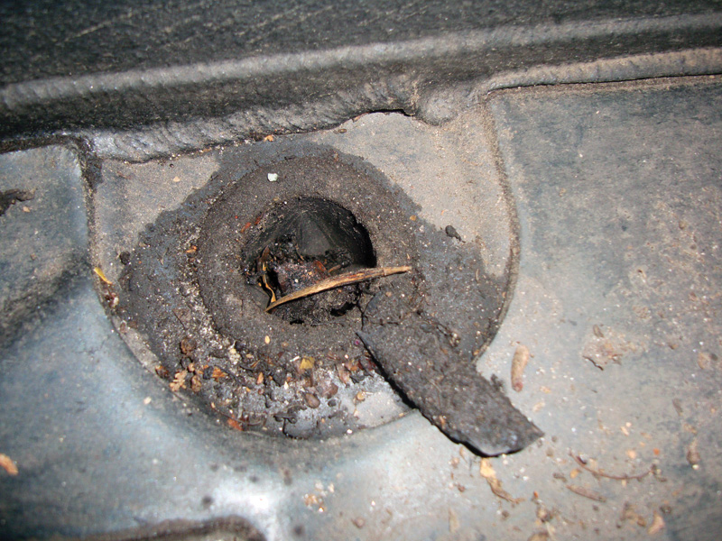
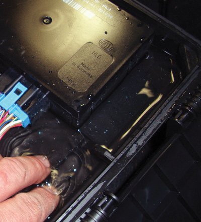
But what’s causing it to happen? Most of you will immediately break out your scan tool (VAG or otherwise), pull codes, and pore over the data stream. That seems sensible, but our investigations point to the need to check some basics first, mostly wiring and connections for water infiltration (see if the sunroof and cowl drains are clear), corrosion, or loose pins in the connectors. Junction boxes, especially near the battery, and various branch connections are especially vulnerable.
In some cases, the important grounds need to be re-established — corrosion again. Unfortunately, this isn’t always discovered until some expensive parts have been replaced, such as the throttle assembly, MAF, or even the ECM. This will, of course, be an embarrassment for the technician and the shop, which is why we always stress checking the basics of wiring and connections early in any driveability or performance diagnosis.
And it’s not just rain water. One tech said he disconnected the coolant temperature sensor only to find that it was full of coolant. He replaced it, but still had the problem along with Code P1171, so he removed the connector at the ECU and found that the liquid had traveled all the way there. Cleaning that cured the no-throttle-response problem.
Four final notes:
- For all the electronic components to work properly, a system voltage of at least 11.5V is required. Check this first.
- Surging and stalling are other possible symptoms of trouble associated with throttle-by-wire.
- After you’ve replaced a throttle valve assembly, you absolutely must run the adaptation procedure (or, throttle body re-learn) of the ECM to the throttle control module (J338) properly. Refer to “Guided Functions†in the vehicle diagnostic tester. Throttle body position should be at 3% at idle and transition to 100% at wide open throttle. If other, related repairs have been done and a problem appears, try running this protocol before you start blaming parts.
- We should mention the logical step of giving the throttle body a thorough cleaning using acetone and a suitable brush. This simple maintenance job has cleared up many seemingly mysterious malfunctions, so it should be done early in your investigation.


0 Comments