Many independent service facility technicians are unfamiliar with Nissan heating, ventilation, and A/C systems. Here’s an overview of the main components of Nissan HVAC systems, and some helpful diagnostic tips and strategies.
Some HVAC problems are easy to diagnose: low refrigerant, low coolant, a clogged cabin filter. But once in a while, a car will roll into your bay that thumbs its nose at you. Of course, the service manual contains the information you’ll need, but it always helps to have a general idea of how a system should work before trying to figure out why it’s not working. Let’s review Nissan HVAC systems so you’ll be primed for your next diagnostic challenge.
A/C
We’ll start by reviewing how the A/C refrigerant loop works. Refrigerant carries heat from the inside of the cabin to outside the car. It absorbs heat when it changes from liquid to gas in the expansion valve as it enters the evaporator. The refrigerant then continues to the condenser where it releases the heat it picked up from the cabin, before the compressor squeezes it back into a liquid so it can repeat the cycle.
For the system to work well, all the components need to be working properly. The compressor must be capable of creating the necessary suction and discharge pressures. The condenser must be free of restriction and have good heat transfer. The receiver-drier must filter out debris and remove moisture that might reduce system performance. The temperature sensing bulb and expansion valve must open to allow flow, and close to prevent freezing and blockage. The cooling fans must pull cool air over the condenser to remove heat. Finally, the system must have enough refrigerant charge to move the heat, but not so much that low side pressure can’t drop. We’ll cover how to test all of this later in this article.
Heat
The heater is a loop system as well. Heat generated by the engine is put to use to warm the cabin. Engine coolant is pumped from the block to the heater core using the engine’s water pump, an auxiliary heater pump, or both. Once the warm coolant reaches the heater core, the blower strips the warm air radiating from the heater core and blows it into the cabin. Some vehicles also use a Positive Temperature Coefficient (PTC) electrical heating element in addition to the heater core, or in the case of the LEAF, to warm the coolant, as there is no internal combustion engine to generate heat.
For the heating system to work, the thermostat must allow the coolant to reach operating temperature. Cold engine coolant can result in a cold driver. The water pump(s) must also be working properly to keep the coolant flowing. Finally, the coolant level must be correct. The heater core often sits relatively high in the system so when the level drops, the heater core fills with air, which is a poor conductor of heat.
Controls
We’ve covered how the evaporator gets cold and the heater core gets hot, but there’s a lot more to the HVAC system. The system must be made to do the driver’s bidding. It’s not enough to have hot and cold under the dash; the driver must be able to choose the temperature he wants and where the warm or cold air is directed.
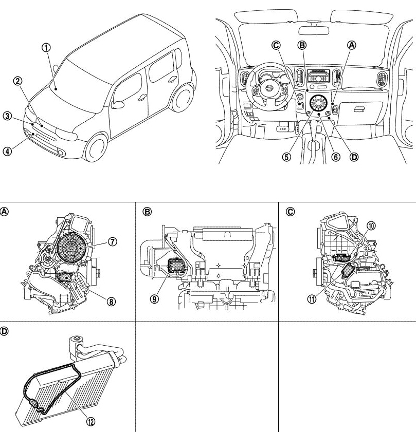
Diagnostic strategy will depend in part on the accessibility of the various test points. Knowing where the components are located is important when developing your plan of attack.
Once upon a time the driver would direct air flow through the use of levers, cables, and flaps; acting as a human thermostat and adjusting the system when he noticed he was uncomfortable. Modern vehicles are far more automated; the driver lets the system know what he wants and a control unit makes it happen, leaving the driver to concentrate on driving. Fuzzy logic allows the system to make decisions much like a human. Adjusting a manual system may seem simple to us, but our comfort actually requires that thousands of rules be programmed. Sensors monitor temperature and sun load, and the controller adjusts air flow and temperature to our liking.
The climate control unit is either integrated into the control panel or a separate unit using the control panel as one of its inputs. If separate, the control unit is usually called the “A/C Auto Amp†or “Automatic Amplifier.†If integrated, the control unit may be called the “Front Air Controller†or “A/C Auto Amp.†A quick check of the system description section in the service manual is always a good plan. Knowing the players, their names, and where they’re located is a big help.
A single control unit is “in charge†so to speak but, these days, most outputs are not directly actuated. Instead, outputs are able to work on their own once they have instructions. The controller and the outputs are connected via a network. The controller might issue an instruction to the blend door to open 30%, and the blend door will carry out the instruction on its own. In older systems, the controller would send a PWM signal to the blend door servo and monitor the position sensor voltage change. Now the controller is more like a manager of autonomous employees. This is great for technicians because the networked outputs can be tested using a self-diagnostic function or the CONSULT. Check the service manual; even some very old Nissan products have surprisingly robust self-diagnostic functionality.
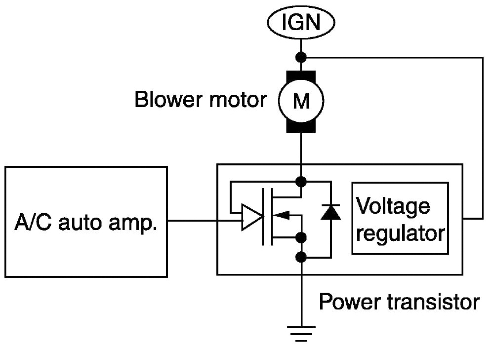
Solid state blower motor control is more efficient and offers a greater degree of control than a set of switched resistors in series with the blower motor.
Outputs
BLOWER MOTOR
Typically the blower motor is controlled by duty cycle. The more on-time, the faster the motor spins. The A/C auto amplifier ramps the blower motor speed up slowly to prevent an unpleasant blast of air. Also, after a cold start it may not run the blower for a while to prevent the driver from being hit with a chilly burst of air. Once the coolant warms a little, it will ramp up to the optimal speed.
MODE DOOR MOTOR
The mode door directs air flow to the defroster vents, dash vents, floor vents, or a combination of two or three. Door position information is often sent to the control unit via a single wire network connection. The mode door position can be automatically selected on vehicles with automatic climate control. Mode door position can be directly controlled using the self-diagnostic functions explained in the service manual.
AIR MIX DOOR MOTOR (BLEND DOOR)
The air mix door directs air flow over the heater core, evaporator, or a combination of the two. Its position can be automatically adjusted on vehicles with automatic climate control. Air mix door position can be directly controlled by using the self-diagnostic functions explained in the service manual.
INTAKE DOOR MOTOR
The intake door switches the intake side of the blower duct from outside air to inside air. The A/C auto amplifier will automatically select the optimal door position on vehicles with automatic climate control unless the driver overrides it. The intake door function can be tested using self-diagnostic functions explained in the service manual.
A/C COMPRESSOR CLUTCH
The compressor clutch engages or disengages the compressor from its drive belt pulley. Typically, the climate control unit sends a “clutch on†request to the ECM, which relays the request to the IPDM E/R provided the engine is not overloaded or overheating. The IPDM E/R sends 12V power to the compressor clutch coil. The coil usually grounds directly through the compressor body.
Inputs
Sunload SENSOR
When the sun shines on you, it feels warm. The sunload sensor input helps the A/C auto amp compensate for this. Typically a sunload sensor trouble code will set any time there is no sun (like when you’re in the shop). Shine a bright flashlight on the sunload sensor to clear the code.
Refrigerant Pressure Sensor
The Refrigerant Pressure Sensor breaks the compressor clutch circuit when the pressure becomes too high or too low. A high pressure will strain and may damage the compressor. A low pressure usually means low refrigerant, which also means poor lubrication for the compressor.
DEFROST
Even automatic A/C systems need driver input to activate the defroster. The rear window defroster is usually a resistive grid built into the rear window. The front window is defrosted by directing blower output to the windshield and front side windows, using fresh air, and using the A/C to dehumidify the air.
RECIRC
Recirculation can be manually controlled or controlled by the A/C auto amp logic. In defrost mode, the auto amp will switch to fresh. When maximum cooling is needed it will be switched to recirculation.
AMBIENT TEMP, INTAKE TEMP, & CABIN TEMP
The A/C auto amp uses ambient air temperature, inlet air temperature and cabin temperature to help plan its strategy for keeping the cabin comfortable.
COOLANT TEMP
The A/C auto amp uses the coolant temperature in its decisions on blower operation. There’s no point in blowing air over the heater core if it’s still cold.
VSS
The VSS is also used in making decisions about blower operation. Blower noise will be less noticeable when vehicle speed and road noise are higher.
System Diagnosis
Start by taking inventory of what works and what doesn’t. This will usually take care of the first step in diagnosis as well. Verify the customer’s complaint. Start in the cabin by checking the following functions:
- Does the blower work in all speeds?
- Does the mode control switch air flow between floor, vent, defrost, etc.?
- Does the vent temperature get hot with the heater on?
- Is the vent temperature sufficiently lower than ambient temperature?
- Do the defrosters work normally?
What to check next depends on what problems you find during the function checks.
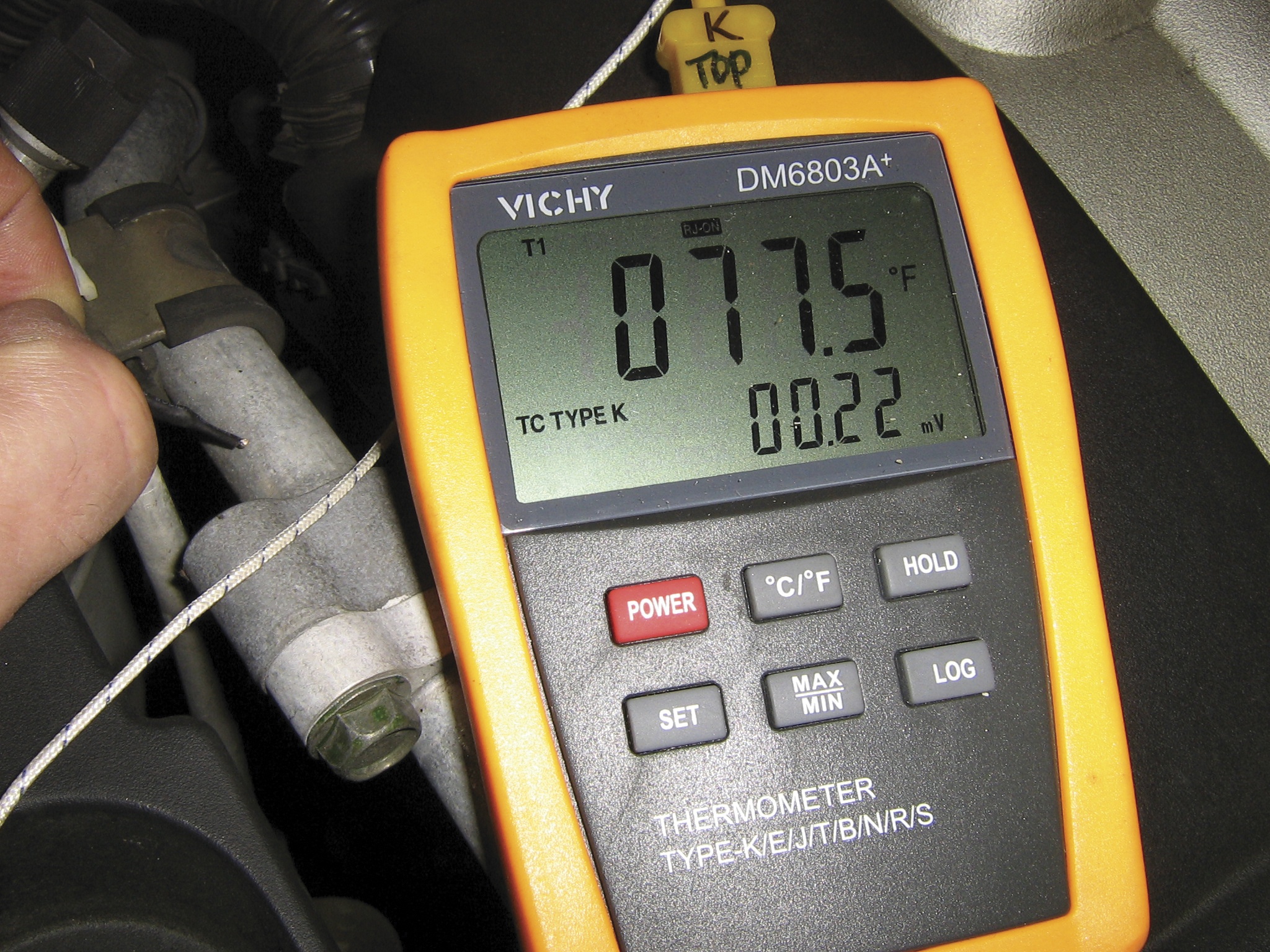
A contact pyrometer is a very useful tool for climate control diagnosis. An infrared thermometer can also be used, but reflective metallic surfaces or attempting to measure small areas can lead to inaccurate readings.
The Vent Temperature is Not Cold Enough with the A/C On
How cold is cold enough? There are many rule of thumb specifications, and they may be adequate for a quick check, but the best way is to follow the test procedure in the service manual. This means setting conditions exactly as they’re outlined in the manual and taking humidity into account. If you don’t have a hygrometer, just check the National Weather Service’s website at www.weather.gov. You can look up local humidity by entering your zip code.
If cooling is inadequate, start by dividing the system. Is the problem in the refrigerant loop or somewhere else in the climate control system? A quick way to find out is to check the low side line temperature at the evaporator. It should be pretty cold, usually around 40°F. If it’s cold but the vent is not, check the climate control. If it’s not cold, check the refrigerant loop for problems. A quick check to see if the compressor is engaged is a good place to start. If it is, check pressures with an A/C pressure gauge set. If not, check into the compressor clutch control.
Pressure gauges are an under-used diagnostic tool. Often, a technician may not be confident in his ability to interpret the pressure readings. The truth is you don’t need to be a thermodynamic guru to use a pressure gauge set to accurately diagnose an A/C system. The service manual has a chart that provides normal and abnormal pressure readings and their meanings. Look at the gauge readings. Find similar readings in the chart. Read the information in the probable cause column.
Depending on where the service ports are in the refrigerant loop, it’s sometimes possible to have good pressure readings but poor cooling. The loop is kind of like a series circuit, where all of the voltage drops are equal to the source voltage. Ideally, all the voltage is being dropped across the component doing the work instead of being wasted in parts of the circuit with high resistance.
Restrictions in the A/C loop can cause pressure drops. This is bad because, when the refrigerant goes from higher pressure to lower pressure, it goes from higher temperature to lower temperature. When this happens somewhere other than in the evaporator, it doesn’t help to cool the cabin.
So, how can we find restrictions in the A/C system? Well, because we know a restriction will cause cooling, we can check for cold spots. A pyrometer could be used for this, but feeling with your hands will work just as well. Restrictions usually occur in the receiver-drier, condenser, or in a damaged or kinked line near the condenser. To check, just compare the inlet and outlet temperatures of the receiver-drier, feel the condenser in several places for cold spots, and run your hands along the lines to check for kinks or cold spots.
Finding A/C Leaks
The most frequent problem with A/C systems is low refrigerant caused by a leak. An A/C sniffer can be used to find leaks, but UV dye is arguably a much better method, with the possible exception of finding an evaporator core leak. It’s worth noting that removing the cabin air filter will often provide a line of sight to the evaporator core, which can be used to check for leaks with UV dye.
Before charging the system, do a careful visual inspection. When refrigerant leaks, oil also leaks. Unlike the refrigerant, the oil does not evaporate and leaves behind an oily dust-collecting stain. Check exposed areas of the condenser and O-ring joints, hose to line crimps, and the compressor seal area for stains. It’s also possible that dye has been added to the system in the past, so a quick inspection with a black light is worth a try.
A vacuum decay test is also a good plan before adding any refrigerant. It will not find small leaks, but it will prevent adding refrigerant to a system that may lose refrigerant as fast as you add it.
No Heat
Poor heating complaints are often due to low coolant or a stuck-open thermostat, but can also be caused by issues with the blend door, heater control valve, water pump or auxiliary water pump, PTC heater, or even a restricted heater core.
Checking for low coolant is pretty straight-forward, but be sure to consider the possibility of air pockets. Many Nissan products have cooling system bleeders to help trapped air escape. The Nissan cooling system fill tool can also be used to avoid trapped air.
A stuck-open thermostat can be found by monitoring the temperatures of the upper and lower radiator hoses while the engine warms up from cold. Assuming the lower hose leads to the thermostat housing, the upper hose should slowly increase in temperature and the lower hose should stay relatively cold. When the coolant temperature reaches about 180°F, the lower hose temperature should rise quickly. A CONSULT is a great way to monitor the coolant temperature for this test. If the temperatures of both hoses rise equally, the thermostat is stuck open or missing.
Here’s a quick and easy water pump test: squeeze the upper radiator hose and snap the throttle. You’ll feel a pressure pulse every time the throttle is snapped. Unfortunately, there are no newer Nissan products with cable actuated throttles, so this test is limited to older models.
The self-diagnostic functions or a CONSULT will help with diagnosis most other issues.
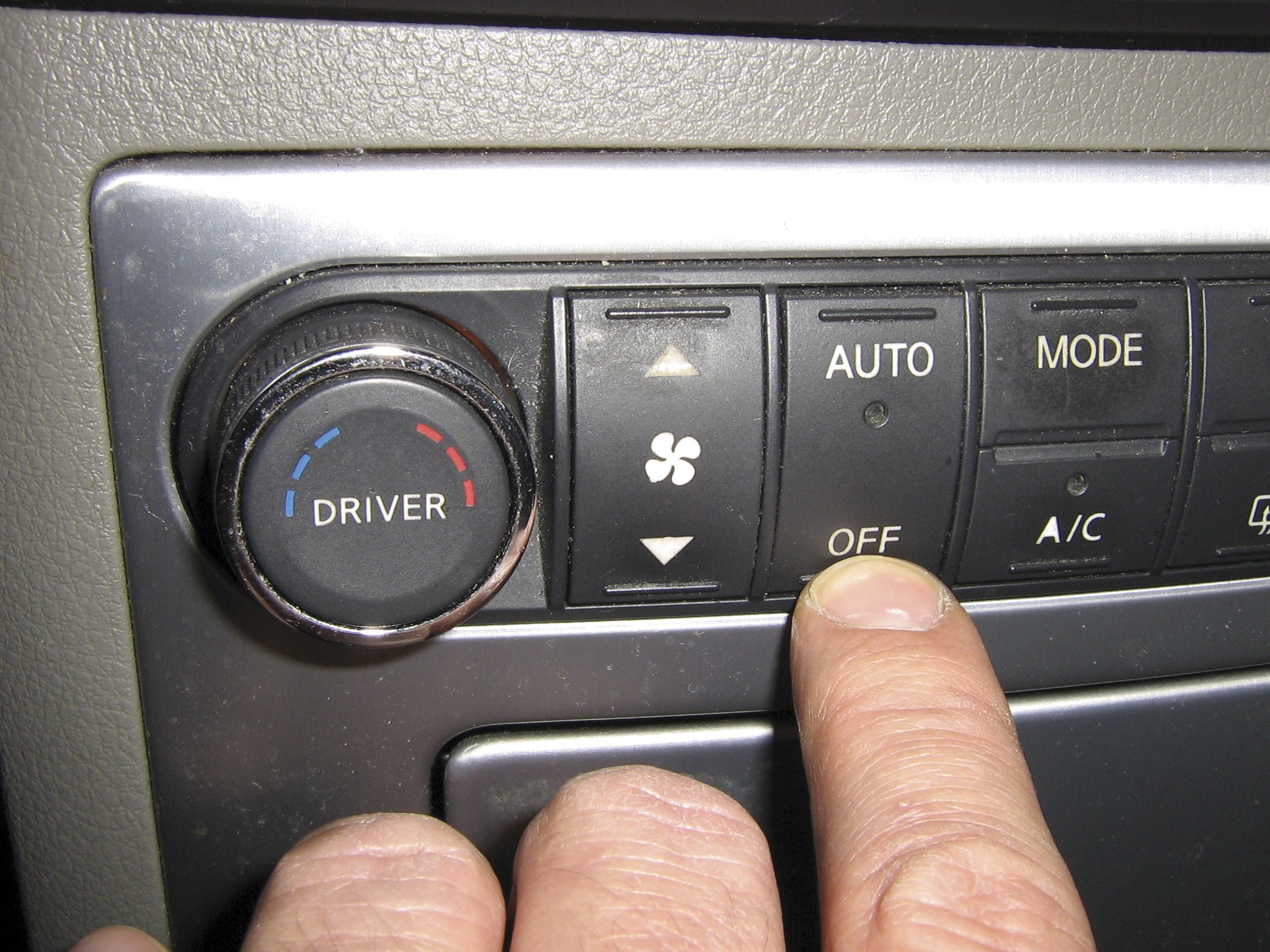
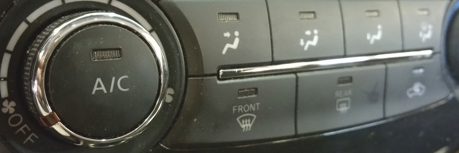
Press and hold the OFF button for five seconds right after starting the engine to enter self-diagnostic mode.
Self-Diagnostic Functions
A/C Auto Amp inputs and outputs can be tested using the self-diagnostic function built into the A/C Auto Amp – no CONSULT required. Typically the self-diagnostic mode can be activated by starting the engine, then pressing and holding the OFF button on the climate control interface for five seconds. You must do this within 10 seconds of starting the engine. Navigation once in the self-diagnostic mode is usually accomplished with the temperature control. To exit self-diagnostic mode, either press the AUTO button or just turn the ignition off.
The CONSULT can also be used for climate control diagnosis, although its capabilities will vary model to model. At a minimum, you’ll have active tests for the cooling fans and compressor clutch relay, and data list items for the Refrigerant Pressure Sensor, coolant temperature, compressor request, and cooling fan request.




When the temperature control knob in my 2012 frontier is in a middle position (not fully on or fully off), I hear a “flapping” noise coming from somewhere behind the instrument panel. What is causing this?
Jerry Salatino
salatino49@gmail.com