Accidents happen, but don’t miss something that could contribute to another.
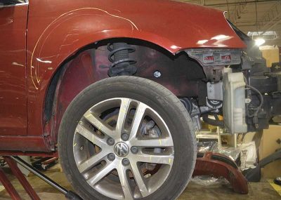
Anti-lock brake system (ABS) components are on every corner of modern Volkswagen vehicles, and in the event of a collision are vulnerable to damage that can reduce braking operation. Incomplete or improper repair of brakes after a collision can increase the body shop’s risk of liability for future accidents due to brake system failure. Even if you sublet ABS brake repair, you should have a thorough understanding of what is required and whether the service provider you partner with has the knowledge and skills to make the correct repairs.
Restoring braking ability
A rotor that has been bent or cracked in a collision can knock the caliper pistons back away from the disc surface and slow application enough for it to be recognized by the ABS control module, and may cause pulsation. Damaged mounting hardware can prevent a caliper from developing the desired clamping force on the brake pads. An axle and related support components, if damaged, can alter the ability of the suspension to handle the load transfer as vehicle weight shifts from the rear to the front during braking.
These are examples of brake system components that require the same precision measurement as structural members to restore functionality after an accident.
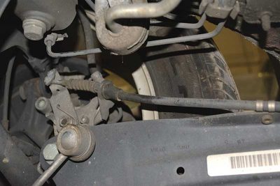
Your visual inspection should also include attention to the condition of brake lines, hoses, connectors, sensors, and other components. Any cracked or kinked lines, components that are leaking brake fluid, damaged sensors, connectors and seals, and cut or worn electrical wires must be replaced.
After repairing collision damage, use a scan tool to pull any trouble codes that relate to the braking system.
Sliding or scraping?
Anti-lock brake systems (ABS) are based on the principle that a wheel that is rotating slowly has more traction in an emergency braking situation than one which is under a constant maximum brake pressure and is locked. Maximum traction is achieved when a tire is scraping the road surface no more than 20 percent of the time, rather than locked and sliding constantly.
ABS technology achieves this by applying brake pressure just until the tire stops rotating, then backing off slightly to allow the wheel to spin a little and maintain traction. This pressurizing and de-pressurizing the brakes occurs up to eighteen times per second.
The increased traction helps prevent loss of directional control, and slows the vehicle in less distance than would a knee-jerk slamming down on the brake pedal in a non-ABS vehicle.
ABS first appeared on production vehicles in the late 1970s, and has naturally evolved over the decades. First, there were three-channel configurations that managed the two front wheels independently and the two rear wheels via a single channel. There was even a simple one-channel system used on some domestic pickups and SUVs that only prevented lockup of the rear wheels.
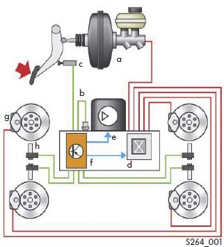
Volkswagen first adopted ABS for the 1986 Passat, and all late-model VWs employ the four-channel configuration – all four corners have sensors to measure wheel speed and separate lines to carry brake fluid pressure.
Wheel speed basics
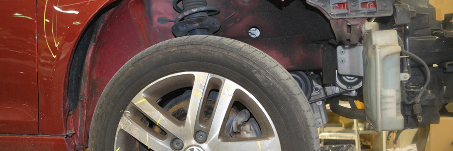
A collision that damages wheels is likely to also have damaged key ABS components, depending on which area of the vehicle was hit. The wheel speed sensors especially, but also the lines and wiring, are vulnerable to collision damage, and must be repaired in order to restore proper braking.
ABS components are very reliable elements of Volkswagen vehicle safety systems. Post-collision problems with ABS are far more likely to be the result of a damaged component or circuit than a design or manufacturing defect. As already mentioned, one component that is very vulnerable to collision-related damage is the wheel speed sensor (WSS).
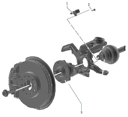
Wheel speed sensors monitor and provide speed data to the ABS, traction control (TCS), and stability control (ESC) systems. The WSS receives information about the rotational speed of the tire from a toothed wheel, called a tone ring, located on or in the wheel hub.
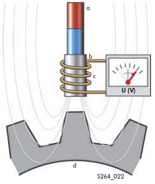
The sensor sits near the tone ring and measures the strength of the magnetic field generated as the tone ring rotates. When a gap between teeth is close to the sensor, the magnetic field is weak. When a tooth is close to the sensor, the field is strongest because metal conducts magnetic force better than air.
The wheel speed sensor picks up the strong or weak magnetic field as either a high or low voltage. The voltage data from the wheel speed sensor produces an alternating current (AC) waveform, or if it is a digital WSS, a square wave output. This voltage signal varies in frequency with the speed of the rotating tone ring.
The voltage data goes to the electronic brake control module (EBCM), which in turn uses it to actuate solenoids that increase, maintain, or decrease brake fluid pressure from the master cylinder to an individual brake circuit.
Visual inspection of ABS components
Look for obvious signs of damage. Easy to spot are a cut wire, crushed sensor housing, cracked connector, or missing tone wheel tooth. Any of those problems are enough to weaken, destabilize, or outright block the wheel speed sensor signal from reaching the ABS control module. ABS functionality will be reduced or eliminated, and the vehicle will have to rely on the old-fashioned, unregulated hydraulic braking until the WSS signal problem is solved. The ABS will set a fault code and illuminate the dash warning light.
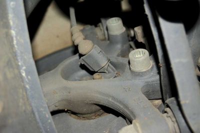
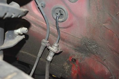
For example, too wide or narrow an air gap between the tone ring and wheel speed sensor can cause the WSS to send an inaccurate voltage signal to the ABS control module. A variation of only 0.010 in. on a single tooth can cause a significant fluctuation in WSS signal output. This can occur if the sensor or its mounting bracket is broken or bent in a collision.
The fix is easy. If inspection reveals missing, broken, or chipped teeth on the tone ring, replace it. If the sensor is damaged, replace it, and assure that the bracket is oriented to hold the sensor at the proper distance from the tone ring.
Metallic debris, possibly from collision damage, that has gotten stuck in the space between two teeth on the tone ring can cause a false sensor reading. Also, metallic debris sticking to the end of the magnetic sensor can change the air gap, as can debris that becomes wedged under the sensor and alters its height or angle. If you find a buildup of metallic debris on or under the sensor, clean or replace it.
Choose Genuine Volkswagen parts to make sure that they match other components in the braking system. For example, if your repair includes replacement of a CV joint, brake rotor, steering knuckle, or axle, and the new part includes the tone ring for wheel speed measurement, Genuine Volkswagen parts will have the correct number, size, and location of teeth. The wrong design or number of tone ring teeth will cause the sensor to read too fast or too slow, and set an ABS trouble code. Repair the underlying problem, reset the ABS, and check to see if the same code reappears.
Refer to your Volkswagen repair manual for the correct air gap specification. Check the gap using a non-ferrous feeler gauge (brass or plastic). A steel gauge would interact with the magnet in the sensor and you’d have difficulty getting an accurate measurement.
Check for DTCs
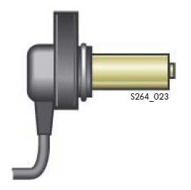
Many different problems can set an ABS trouble code. Before you start swapping costly brake parts on a vehicle, use your scan tool to check for stored diagnostic trouble codes (DTCs).
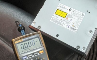
Diagnostic tests and information available in Volkswagen repair manuals and training materials help get the most out of your scan tool, DMM (Digital Multi-Meter), or lab scope. For example, step-by-step test procedures to check for a faulty ABS wheel speed sensor tell you to first turn off the ignition and check the resistance in the sensor. If it is outside of the specification of 1.0 to 1.3K ohms (in this case, for a 1998 to 2005 Golf or Jetta), separate the connector from the sensor, and wiggle the wire slightly while testing. If no malfunction can be found in the wiring, but the resistance of the sensor is out of spec, you need to replace the speed sensor for that wheel.
Before you toss a sensor, even if a DTC points to it, first check to see if tire sizes are mismatched (that would be an embarrassing mistake!), then that there are no problems with wheel bearings or bent wheels. These conditions can alter the air gap and create a false modulation of the voltage signal.
Sine wave or square wave?
You can test resistance and voltage of the sensor using a DMM, or check it and other components with an oscilloscope. A missing or broken tone ring tooth appears on an oscilloscope screen or digital pattern as a missing or deformed section in what should be a repeating, uniform up and down sine wave or square wave cycle as you rotate the tire manually.
An oscilloscope can often catch problems that a DMM may miss. For example, a scope pattern that is flattened or erratic is an indication of a weak signal that is likely caused by too wide an air gap between the WSS and the tone ring.
A buildup of metallic debris on the tip of the sensor can also interfere with the sensor’s ability to pick up an accurate signal. Other possible causes of a weak signal include internal resistance in the sensor or its wiring, or loose, cracked, or corroded connectors.
A quick way to check if the wheel speed sensor is communicating with the ABS control module is to lift the vehicle so all four wheels are off the ground, turn the ignition on (engine off), and rotate the wheel by hand quickly. The amber ABS light should come on, because the control module sees one wheel spinning while the others are not.
Reset the ABS light by turning off the ignition. Repeat the wheel spin test for each of the remaining wheels, resetting the light before each test. If the light fails to turn on for any wheel, inspect the tone ring for missing teeth and cracked or warped body. Inspect the wiring and connections between the sensor and the ABS control module. Check the resistance level of the sensor to make sure it is within the factory-recommended range. If the ABS light does not turn off when the ignition is turned off, the problem is not in the wheel speed sensor.
If your scan tool found no trouble codes suggesting a fault in the wheel speed sensor, remove it and clean the mounting area before re-installation. A buildup of corrosion between the sensor and its mounting surface would cause the air gap to be too narrow, and alter the voltage signal.
Volkswagen Tests for ABS Components
(examples for 1998 to 2005 VW Golf or Jetta only)
| Item Tested | Test Conditions | Specification | Next step if out-of-spec |
| Voltage supply for ABS hydraulic pump to ABS control module (w/EDL) | Ignition switched off | 10.0 to 14.5 V | Check wire |
| Voltage supply for the valves in ABS hydraulic unit to ABS control module (w/EDL) | Ignition switched off | 10.0 to 14.5 V | Check wire |
| Voltage supply (terminal X) to ABS control module (w/EDL) | Ignition switched on | 10.0 to 14.5 V | Check wire |
| Function of brake light switch | • Ignition switched off • Brake pedal not depressed | 0.0 to 0.5 V | • Check brake light switch and read measured value block, display group 003 • Check wiring |
| Function of brake light switch | (additional test) Press brake pedal | Approximate battery voltage | Check brake light switch |
| Resistance of ABS wheel speed sensor | Ignition switched off | 1.0 to 1.3 k ohms | • Separate connector on ABS wheel speed sensor • Check wiring • Wiggle wiring during test • If no malfunction found in the wiring, replace the wheel speed sensor |
| Voltage signal – ABS wheel speed sensor | • Vehicle raised • Ignition switched off |
| Check installation of wheel seed sensor and tone wheel |
| Voltage signal – ABS wheel speed sensor | Rotate wheel at approximately 1 revolution / second | Min. 65 mV alternating voltage | Check whether ABS wheel speed sensor has been interchanged and read measured value block, display group # 001 |
| Supply voltage for connector | • Ignition switched off • Connect multimeter to connector | 10.0 to 14.5 V | Check wiring |
| Resistance of K wire for connector | • Ignition switched off • Disconnect multi-pin connector from ABS control module (w/EDL) | Max. 1.5 ohms | Check wiring |
| Function of ABS hydraulic pump | • Ignition switched off • Pull hydraulic pump connector off control module |
|
|
| Function of ABS hydraulic pump | Connect Ground to connector T2/1 and battery voltage to connector T2/2 on hydraulic pump | Hydraulic pump runs without malfunction (max. 10 seconds) | • Perform output Diagnostic Test Mode (DTM) • Replace control module |
| Function of ABS hydraulic pump | Connect Ground to connector T2/1 and battery voltage to connector T2/2 on hydraulic pump | Hydraulic pump does not run | Replace hydraulic unit |


0 Comments