
We’ve explained the design, operation, and benefits of TSI (also known as FSI, and generically as gasoline direct injection) in previous issues of Volkswagen TechConnect. Now, we’re beginning a series of hands-on articles that will give you the real-world diagnostic and repair information you need to handle VW vehicles so equipped. This time we’ll look at power, the network, and preliminary testing.
This first installment of our series on this ground-breaking system will help you be sure the foundation is sound before you waste time on high-tech diagnostics.
Safety Notes: Being very different from traditional EFI, this system demands extra cautions as follows.
- In all conditions and in all circumstances, if the fuel lines, transducers, and regulating systems are opened, disconnected, or damaged, FUSE 28 (read the schematic!) MUST be removed. When opened, the driver’s door as part of the network will activate fuel pump control module J538 and cause a serious fuel spill that could result in a fire.
- Always follow the official cautions and warnings when opening the high-pressure fuel system lines. Serious injury can result if proper procedures are not observed – the pressure is high enough to force gasoline through your skin. Bleeding down fuel system pressure is an important facet of service.
- TSI injectors often actuate at approximately 70V and 10 amps, with the capability to rise to over 120 volts, so a serious shock hazard is present.
Just as with most other automotive tasks, the most important step when trying to solve an issue with a TSI VW is getting information from the customer. Asking the correct questions and requesting a timeline of the performance defect or fault with the vehicle paints a picture so that the technician can “walk in the customer’s shoes.†Ideally, you should take a test ride with the customer aboard. Nothing good will happen if you’re not both talking about the same thing at the outset.
Juiced up?
Believe it or not, one of the most common (and basic!) causes of trouble with TSI is battery voltage and capacity. Really. We’ve seen many cases where technicians have wasted a great deal of time and practically torn their hair out trying to isolate the cause of a “ghost†problem only to have it evaporate after the simple expedient of installing a high-quality new battery with the proper rating for the vehicle in question, something that’s readily available from your local Volkswagen dealer’s parts department.
Human nature being what it is, you’ll often find that the customer has installed the cheapest possible battery that will physically fit in the space provided. As an early step in your investigation, it makes sense to take a minute to actually read the label and note the amp-hour rating, reserve capacity, and cold cranking amps. The brand matters, too, and if you can ascertain when it was bought either from a sticker, receipt, or notation in the service records, this will amount to another factor to plug into the equation. Even a quality battery that’s four years or more old should be suspect.
Why is this so important? Namely, if the battery can’t supply sufficient juice during TSI testing, or during high-draw operation with numerous network controllers energized, it’s apt to divert you to a fallacious troubleshooting path besides causing driveability problems and perhaps even a no-start. It can cause various parts of the CAN to go to sleep, or function erratically.
To delineate this further:
- The initial quality and size of a battery, the number of years of use, the heat and cold it has endured, and what that vehicle model has installed from factory (or even non-factory equipment) all affect its capacity to keep the CAN properly powered. In today’s vehicles, batteries are much more heavily taxed than they were in earlier models.
- See below a partial list of network controllers that become active when the driver’s door is opened.
- If the battery is in poor condition and multiple controllers are activated in repetition, expect strange, often repeating, faults.
- Repeated or prolonged testing will deplete a battery’s reserve, perhaps to the point of no-start status. In the worst case, some control modules will “lock†so that the security systems will be activated, and some effort will be required to get the engine to crank and fire. That is why the before and after scans are so important. Deleting the faults found will in most cases give the technician the ability to start the vehicle.
Testification
So, what’s the best way of making sure that battery has the moxie it needs to keep the electronics and electrical devices running properly? There are many approaches to finding this out that range from decades-old procedures to the most modern techniques and equipment. If we were asked how to do it in the form of a multiple-choice question, we would likely answer “all of the above.â€
Of course, we recognize that this is supposed to be an article on diagnosing TSI trouble, but a review of the means of determining the health and essential strength of a battery might help save you from spending diagnostic time needlessly, or, worse yet, making an erroneous diagnosis and perhaps replacing perfectly good parts. Therefore, we’ll run through all the possibilities:
- Heedless of suggestions to the contrary about first establishing a vehicle-wide baseline, we’ll bet you’ve already plugged in your scan tool. Okay, note the voltage present and compare it to a temperature-corrected chart for lead-acid batteries. Observe cranking voltage while starting the engine, and make sure base voltage goes up at least one volt at idle. Even the simplest OBD II scan tools have this function, although to go much beyond this level of troubleshooting you will need a much more capable tool such as a VAG or a laptop-based system that will unlock specific VW information in many specialized data groups and enable bi-directional control. Of course, you could use a DMM (Digital Multi-Meter), or even an analog voltmeter, across the terminals for this first step in battery testing.
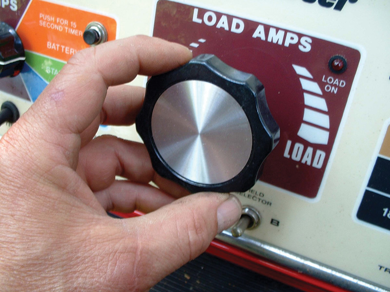
- We’re still fans of the traditional VAT (Volt Amp Tester). Its carbon-pile load will tell you things fancy electronic “smart†testers can’t. It gives you true reserve-capacity information.
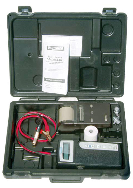
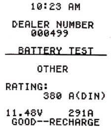
- Presumably, you own a modern impedance-type “smart†electronic battery tester, so don’t be afraid to use it. One advantage to this is the printout for the customer, or a warranty claim.
- We’ll get really primitive here and state that a hydrometer test is still definitive in many cases providing the configuration of the cell vents permits it. You’ll identify the dead cells and the unevenness that points to sulfation.
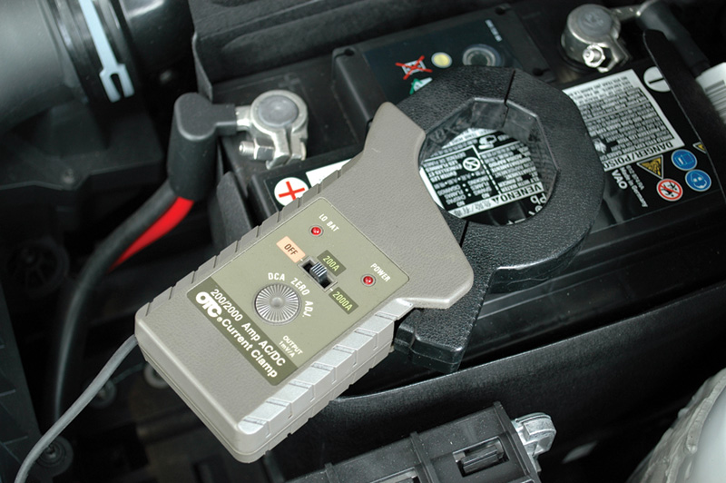
While we’re on the subject of electrical testing, we should mention two other essential tools. First, the “amp clamp.†Years ago, the only way to find out how much actual current was flowing through a wire was to break a connection and install an analog ammeter of sufficient capacity in series, which was time-consuming. An inductive clamp that you simply put around the wire in question and attach to your DMM or oscilloscope is a great convenience, but you must be careful to only use one of high quality or the readings may be wildly inaccurate.
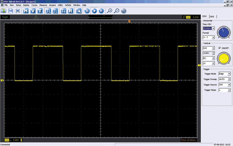
Second, the oscilloscope (otherwise known as a lab scope and not to be confused with an old-fashioned ignition oscilloscope), gives you real-time readings and catches otherwise unseen intemittents in any electronic/electrical testing. It offers a true image of anomalies or “noise†in a circuit. It may take some mental discipline to learn how to use it, but once you become proficient you won’t want to settle for anything less. In battery/starting/charging applications, it will show you the alternator ripple voltage that might not be picked up by a DMM or VAT and that can raise havoc throughout a vehicle’s electronics.
Keeping up with demand
Even if you’ve confirmed that the existing battery is healthy, or if you’ve just installed a new, high-quality unit, what will happen during extended periods of troubleshooting or reprogramming/reflashing? The voltage of even a robust battery can easily fall below the threshold that ensures full CAN operation and accurate testing.
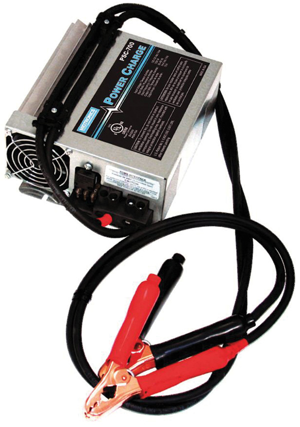
The answer, of course, is a dependable, ripple-free auxiliary power supply. Many technicians don’t understand how power-hungry modern vehicles are. During any test, any program update, or vehicle scan, a power supply – NOT a battery charger – should be attached to the electrical system. Professional shops typically use a 90A floating power supply for testing and flashing. If battery voltage is allowed to drop, expect some CAN (Controller Area Network) systems to go to sleep and go off-line. Expect some adaptations to be reset, and customer preferences to be “forgotten.†Expect fault codes and other anomalies that were not present when the vehicle came into the shop to now be evident and require your time and attention to rectify. In simple terms, a good, steady power supply helps ensure that the vehicle will leave your care with no faults in the CAN system.
System scan
Once your auxiliary power supply is attached and turned on, the next step is to scan the entire system, and save this first scan-shot and baseline test. Some PC-based scan tools will do that test in text that can be saved, emailed, and printed. It is also read using MS Notepad. Use this as a guide, then delete all faults, reset, and exercise the systems again. Rescan and see what faults return within the network. If possible, photograph the PR tag code in the trunk, or find the vehicle-specific owner’s maintenance manual. That same PR code should be on the second page of that manual. This code clearly identifies what is in that vehicle and how it was built in the factory.
To go back to customer communications for a moment, the steps you’ve taken so far should amount to between 0.5 and 1.0 hrs. of shop time. It is reasonable to include these steps in the work order as part of the estimate. It is not unexpected to spend a few hours to prepare and test a fuel system in a VW.
CAN do
Some details of the CAN in these VW models is appropriate here. To begin with, the moment the driver door is opened, many network controllers become active:
(A) Comfort control address 46 (J393)
(B) Instrument cluster electronics address 17 (J285)
(C) Engine electronics address 01 (J623)
(D) Fuel pump (G6)
(E) Fuel pump control module (J538)
(F) Central electrics I address 09 (depending on model) (J519)
An interesting test is to attach a DMM with an amp clamp around the negative battery cable and measure the actual current draw on the model under test. You may be surprised at how much current is measured when first opening a door, and later notice the change when the fuel pump control module shuts down. Measure again when cranking or with the key in the ON position. Record those measurements for future reference. That same test can also be of interest when an auto-scan is being performed. Again, record the values. Not all vehicles will consume the same amount of battery power. That will depend on what components and options were installed at the factory.

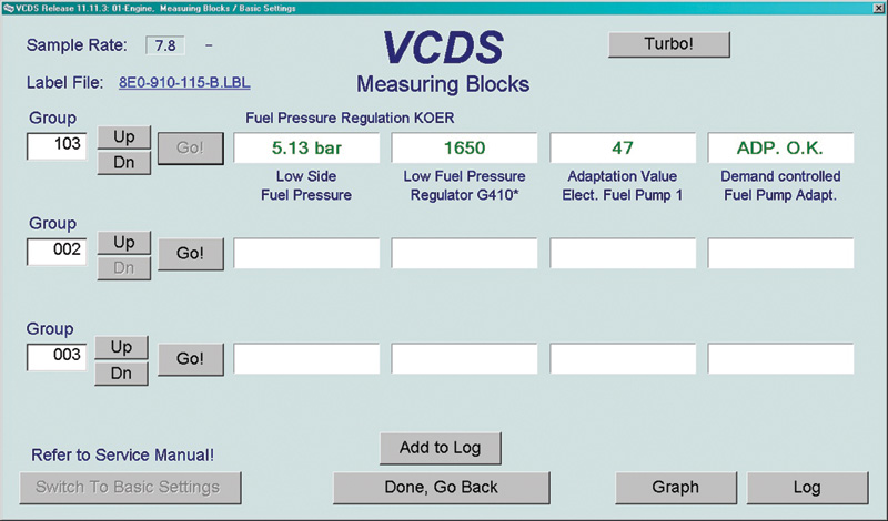
PSI
Fuel pressure is another important basic parameter to check. With an oscilloscope, the technician will be able to see how the pump behaves via the fuel pump control module. With a normal running TSI engine, the duty cycle will change with engine speed and engine load. Using a scope and scan tool, those measurements can be viewed easily. In more and more shops, two laptops, a scan tool, and a scope on a diagnostic cart have become the norm. Screen captures and screen movies have also become common, and saving this data for future use makes a great reference.
Random
We’ll conclude this installment of Volkswagen TechConnect’s TSI coverage with some important points:
- If a fuel pump or fuel pump control module is suspected as the fault that’s causing a no-start, measure the battery’s state before you engage in more complex diagnostics.
- If the weather is hot and the engine is at operating temperature and NOT running, expect the fuel pump control module to be active for quite some time after the ignition key is removed. The hotter the engine, the longer controller J538 and the pump will be active. Therefore, a cool engine will equal a shorter ON time for J538. The rationale is heat soak – maintaining pressure until the engine cools helps eliminate this condition by collapsing vapor bubbles in the fuel system. This is yet another reason why the battery must be in excellent shape.
- The above situation means that besides the fuel pump and controller J538, the ECM remains ON as well. Test that on some hot day with a scan tool at address 01 with the key removed, and you’ll see these results:
- (a) The ECM will remain active.
- (b) The fuel pump controller J538 will remain active.
- (c) Battery voltage and reserve will drop.
- (d) Network activity will remain ON until the temperature drops.
After any repairs, all faults must be cleared, fuel pressure adaptation MUST be carried out, and a fuel integrity check should be done before doing a road test.
Download PDF


0 Comments