
There’s a whole lot more to the science of camshafts than you probably ever imagined. This series will help you make the right choice.

There is a lot more Big Science ground onto this simple device than first meets the eye. A cam is about timing the event, maximizing the flow at a specific point, controlling the valve, and keeping the lifter, pushrod, rocker, spring, and valve stable throughout the operational range of the engine. And, of course, it’s all a compromise among the goals of economy, power, torque, and drivability.
While we in this industry think of cams as something unique to the automotive engine, they are, in fact, common to all manner of contraptions in the world of manufacturing and machine control. There are disc cams, rotary cams, wedge cams, roller gear cams, inverse cams (where the cam is stationary and the follower moves, not inverse lobed cams, more on that later), cylindrical cams, and translating cams to name just a few found in industry. For our purposes, we will from this point on only refer to the camshafts we all know and love, but it’s important to remember that ours isn’t the only industry where cams are found.

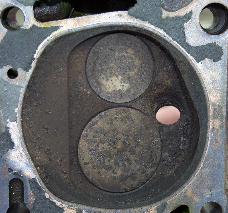
Taken from the crankcase, in this photo you can see how on this head the intake valve is significantly larger than the exhaust, and how the plug has been relocated to a more central location in the bore. The chamber form is very shallow, the valves are tipped away from the bore walls to help unshroud them and there is a lot of quench area showing. With tight 65 cc chambers, this head uses a piston with a dome on it of only about 1 cc to achieve a static compression ratio of 16.8:1. Central plug location means that the flame front progresses across the chamber more uniformly, the shallow chamber means that the surface area-to-volume ratio is good, and the extended quench zones help induce turbulence to speed combustion and keep the mixture stirred. This is a very efficient chamber, typically using only 28-30 degrees of spark lead at 8,000 rpm on a 4.625 in. diameter bore.
Trapping air
In the most common forms of the automotive racing engine, we attempt to consistently and uniformly trap the most mass of air and fuel above the piston, light it off, convert as much of the chemical energy into heat energy (released during combustion), then into the mechanical energy that drives the car forward. The crankshaft converts the reciprocating linear motion of the piston and the swinging connecting rod to rotary motion for delivery to the transmission and differential, while the camshaft (cam shaft, as two words, means a shaft with a cam or cams on it) converts the rotary motion of the shaft to a linear motion via the lifters or followers, or some combination thereof. The goal is to precisely and accurately translate the cam lobe designer’s lift, duration, and event timing into accurate valve motion via the lifter, pushrod, and rocker system on an overhead valve engine, or directly into valve motion on an overhead cam engine on direct acting systems, or through a follower and lifter on indirect acting systems.
If we are high-performance overhead-valve engine builders, and if the cam grinder has done his development work correctly, from that point on our job as a builder is to make the lift and duration designed into the cam actually appear at the valve retainer — by using the lifters, pushrods, rocker arms, valve springs, and valves that most closely meet the required stiffness to match the profile and intensity of the lift and duration ground onto the cam lobes. You must confirm that as much of your calculated lift and timing appears at the valve as is practical. Always confirm your cam at the retainer, with the engine as-built to race.
Pulminary parts
If cams are the heart, then the cylinder heads are the lungs, and between these two is where all power is made or lost; these two parts, or more correctly systems, account for nearly all power production. While the biggest contributors to power, they are a little like a surgeon: They can’t operate effectively without a strong supporting cast. Valve train stiffness and design aside, bores must be round, rings must seal, piston rockover must be minimized, internal clearances properly set, internal oil control and windage managed, and internal friction lowered as much as practical to avoid using up the power produced in an effort to roll over all the internal engine parts at the expense of rolling the tire.
Delicate choices

This is an early, pre-emissions-control street cylinder head. It’s a much larger and much less efficient chamber with notably small valves, too much surface area, and a spark plug location that will make it hard to lead the spark enough to get good power production and stay away from detonation. This chamber is very inefficient and would require roughly 50-55 degrees of lead at 8,000 rpm. Not that it could ever spin that fast with those valves — or without driving over the rods and crankshaft!
There are two ways to buy cams, out of the catalog and with technical assistance. For street or moderate performance applications, buying from the catalog is probably the way most builders choose to go. Doing your own research, you might land on two or three likely candidates and then call in for help in narrowing it down to your final selection, and this is where you might become a bit frustrated. If you call in to three companies and ask for a recommendation after doing your research, you’ll likely end up with three entirely different profiles. This isn’t a conspiracy — selections are made in part by what you explain you are looking for in terms of results and in part by whatever “tribal knowledge†your tech consultants have about your application. They may know several customers with similar combinations and they might have recommended one cam over another several times and gotten feedback on how well it worked for those customers, or they may be using a broad recommendation worksheet that the company developed in house.

Once again, you can see that the chamber is tight and the plug location optimized on this cast iron small block Chevy cylinder head. While the chamber walls have been pulled back to relieve shrouding, the bore is still close since the valves are in line and some shrouding will occur. For this head, I’d expect that it will require about 32-33 degrees of lead at 8,000 rpm.
This is where our conversation gets a little dangerous. We can talk about “general rules†and “general applications,†but we do this at the expense of specific knowledge about how a specific cam will work in a specific engine. I’m not nearly expert enough to tell you what to do or not do when it comes to cam selection, but I can help you with some general rules and engineering principles that apply to cam buying and installation. That said, as a practical matter, if you are building serious racing engines you will need to consult with your cam grinder to get the best recommendation for your engine and application for every engine you build. The calculations and physics involved in cam development are well beyond the ability of someone lacking extensive engineering training or years of experience, so you absolutely must have the help of those who have both the theoretical chops and the real world practical experience of back-to-back dyno testing to help you maximize your power output. Some companies have online forms to fill out and others use a pdf file that you can download and fill out, but in any case you’ll have to have quite a bit of data to get the best recommendation for your application.
Say what?
They’ll ask things like type of cam (flat, hydraulic, solid, roller — or mushroom lifter if you’re really old-school), then attempt to quantify the desired level of performance you’re looking for (mid-, top-, low-rpm power and torque requirements) and the application (for a circle track car, they’ll need the class you’re in and length of the typical track you race on), and for all other applications the desired output level for street-only use, if it’s a dual purpose street/strip, and, if it’s drag race-only, the class (if you’re class racing). Or, you might be involved in off-road, marine performance, or truck or tractor pulling. You’ll need to know the cylinder head type, manufacturer, modifications, and flow numbers at lifts from closed to 1.00 in. at 28 in. Hg; the engine block type, bore and stroke, rocker ratio, carburetor flow rate, rod length, piston type, make and modifications, static compression ratio, intake manifold type, valve sizes, lifter bore, and porting characteristics, plus vehicle weight, axle ratio, transmission type, operating rpm range from low to high, converter stall speed if you’re running an automatic transmission, and tire size and diameter. They’ll need to know about turbocharging, supercharging, or nitrous use if any of those apply to your application.
Here’s a vintage street engine head with a closed-chamber wedge combustion chamber. It’s a bit of a compromise, but still not too badly done for the era (1969). The plug is more offset to the side than I’d like, but there is some quench area and the chamber is fairly small. The biggest problem we face with this style of head is the shrouding. The chamber walls are vertical and they restrict air flow for almost a quarter of the valve diameter. Getting this chamber to flow will take a cam with more lift than the open chamber wedge shown before — and it’ll take about 36-40 degrees of spark lead at 8,000 rpm (assuming this engine could live at that speed, which it couldn’t!)
There may be other questions as well, so you’ll need to be able to intelligently discuss your combination if you hope to get the best camshaft for your specific use, but all engine design, including the cam selection process, starts with the head and the combustion chamber design, including the ceiling (head and valves) and the floor (piston.) For an all-out racing effort, the cam grinder will need to know how much room he has to work in and how efficient the combustion chamber is for your build.
Dynamic collision paths
Large chambers with big piston domes require a different cam than a shallow, heart-shaped, low-angle combustion chamber because the valves will be attempting to occupy nearly the same real estate as the piston, at least briefly, as the piston transitions over TDC during overlap, with piston-to-valve clearance at the minimum somewhere between 15 degrees BTDC and TDC for the exhaust valve and TDC to 15 degrees ATDC for the intake valve. It helps to think of it as an internal race, piston versus valve. The exhaust valve is “on the spring,†racing the rising piston as the exhaust goes closed while the intake valve is “on the cam†chasing the falling piston as the valve comes open — and remember, increasing rocker ratios increases the rate of lift! The exhaust valve movement is less predictable because it’s controlled by the vagaries of a spring, while the intake is totally controlled by a solid system from cam lobe to valve head, and that explains why minimum exhaust valve-to-piston clearance is typically twice what’s allowed for intake valve-to-piston clearance over TDC. Adding to the mix, small, shallow, efficient chambers run a completely different rate of combustion with far less ignition lead, which also affects optimum cam design. So, if you get asked questions that might not seems pertinent to cam selection, don’t fret — your technical guy is doing his job.
The fact that we will most likely use the advanced services of the cam grinder doesn’t mean that you shouldn’t have a bit of practical knowledge about how the camshaft actually does its job. The practicing racer knows to take advantage of all the resources out there, but knowing how duration, lift, and overlap affect the six engine cycles is handy when you’re thinking about and designing your engine.
Heads first and heavy air
Your design all starts with the combustion chamber. The entire engine is built around first-things-first, and the cylinder head and chamber design and efficiency is the first consideration — the foundation — because everything else is designed around it. Since good cylinder heads are expensive and very good heads are very expensive, it is important to know how to choose your heads. A general rule of thumb suggests that you can support roughly two to two and a half times the intake air CFM in horsepower — an intake that flows 500 CFM can make about 1,000-1,250 horsepower — so if you know your car’s weight and the required performance level needed to run your class, you know how good a cylinder head you have to buy.
We don’t often think a lot about air, how heavy it is and how fast it must move in a typical two-inch by three-inch inlet conduit. Air is light by most definitions — it only weighs about .0807 pounds per cubic foot (at standard temperature and pressure — STP.) All good racers know that air isn’t always at STP, which is why we often tune things a bit for colder, heavier air and hotter, lighter air, as well as compensating for altitude and humidity content when needed. What we need to use is the oxygen from the air, which is only about 21% of the total volume taken in by the engine.
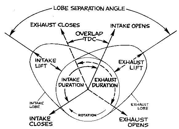
This diagram shows you what to expect, more or less, with your camshaft. The lobe separation angle is the angle between the intake lobe center and the exhaust lobe center, and it’s not as adjustable as you might think. You can roll the lobe centers around a few degrees to “tame†the cam down, but that’s not your best overall solution. You start with lift, which is determined by the application and is based on a percentage of the intake valve size, followed by duration, which follows the lift number you’re trying to achieve because lift and duration have a direct correlation related to how much velocity or acceleration the valve train can tolerate — there are hard limits on both. The intake lobe center is determined in part by the piston movement (reciprocating geometry comes into play), and overlap is the natural result of how much total intake and exhaust duration you end up with.
To put things in perspective, think about your typical bedroom, 12 by 12 by eight feet. At 1,152 cubic feet, that’s less air than is required by a 632 cubic-inch engine per minute at 8,000 rpm (632 times 8,000 divided by 3,456 is 1,462 cubic feet per minute at 100% volumetric efficiency), which means that engine would suck all the air out of your bedroom in less than 50 seconds! At .0807 pounds per cubic foot, 1,152 cubic feet of air amounts to almost 93 pounds, of which roughly 19.5 pounds is oxygen. Now go grab your barbells, carry them into your bedroom and put that together in your head! Hardly seems possible does it? What’s really scary is when you think about a cube of air 100 feet on a side and realize that it weighs roughly 40 TONS! Why is understanding this and thinking about this important? Because moving air in and out of the engine is what makes power and the camshaft is the controlling entity when it comes to air movement. Air has mass and mass and velocity creates inertia. Inertia: A body at rest tends to remain at rest, and a body in motion tends to remain in motion. It’s important to remember that.
Murky math
Now let’s think about the environment we are creating. At 1,000 rpm, an engine is rolling over at 360,000 degrees per minute, 6,000 degrees per second, and 6 degrees per 1/1,000 th of a second. At 8,000 rpm, we are rolling over at 48 degrees per millisecond, starting and stopping an inlet conduit of six to eight square inches on every other stroke creating a violent, pulsing, wet flow with both mass and velocity and, therefore, inertia. Part of that flow we need to somehow stuff into a cylinder, at the right time, over a piston moving at an average of over 100 feet per second (4.625 inches at a time!) and get that intake valve closed before the piston’s upward velocity overcomes the inertial cylinder filling over BDC that the weight and speed of the aforementioned column of air and fuel generates before it leads to intake reversion. If it were easy, everyone would be doing it, right?
At the most fundamental level, our cam selection must balance intake closing with inertial filling, which increases volumetric efficiency (more air stuffed into the cylinder than what the cylinder physically measures) with reversion and backflow caused by piston rise; intake opening with exhaust backflow versus intake restriction (during overlap); exhaust valve opening with improved blowdown versus loss of power extraction caused by venting the cylinder earlier; and exhaust valve closing with exhaust side flow losses and backflow of exhaust into the intake side.
Pulled in
The other consideration of intake open/exhaust closing over TDC overlap is that in a properly designed and tuned racing application, there should be a very high negative pressure present at the exhaust valve that is used to “jump start†intake flow into the cylinder for the next induction cycle. The negative pressure created by the overlap-driven induction cycle is often much higher than the negative pressure created by piston fall by a factor of three to six (15-25 inches of water for piston fall versus over 100 inches of water for the overlap induction).
Every choice you make in camshaft selection is, to some extent, a compromise. You can have drivability, but at the expense of power, torque at the expense of a smooth idle and fuel economy, high-speed operation at the expense of low-speed operation. What you intend to do with your little bundle of nuts and bolts moves power and torque up and down the scale and makes the engine more or less suited to either getting groceries, getting out of the turn or getting down the quarter mile.
In the next issue of Performance Technician, we’ll continue with a few definitions and descriptions, and we’ll begin to examine how event timing varies with engine speed and design. Stay “tuned.â€
IFT to flow rateThis is a spreadsheet that I made up of the flow rates (at 28 inches of water) for a set of cylinder heads I use. First of all, note that the intake-to-exhaust valve ratio is at 75.5%, which is considered “middle of the road.â€Â A Pro Stocker might have a ratio of as little as 65% to allow the engine to run the compression and rpm it needs to to be competitive. High-compression naturally-aspirated engines are more efficient earlier in the expansion phase than low-compression engines and can use larger intakes and smaller exhaust valves than low-compression engines. If you look at cylinder pressure decay in a low-compression engine it, falls slowly — almost linearly at a 45 degree angle — and usable power can be extracted for more crankshaft degrees during the power stroke. With a high-compression engine, the cylinder decay curve looks like it’s nearly a vertical drop as the piston falls from TDC. Because all the usable energy is extracted well before BDC on the power stroke, blowing the exhaust valve open early doesn’t affect power production nearly as much as doing so would on a low-compression engine. The bore size of an engine limits the combined sizes of the valves, but you can shift the ratio, using a larger intake, which only has about 20 inches of water pressure differential inducing flow around it, and a smaller exhaust valve, which when opened earlier might have 60-100 psi differential available to induce flow during the blowdown portion of exhaust. Using that excess pressure to dump exhaust gases would then reduce pumping loss and exhaust flow restriction during the piston-driven exhaust phase. It’s important to remember the relationship of the pressure units we use in this conversation: 1 pound per square inch (psi) is equal to 2.04 inches of Mercury (in. Hg), which is equal to 27.68 inches of water (in. H2O). If you think of psi as a coarse measurement, inches of Mercury as a medium, and inches of water as a fine measurement, it’ll help you keep things in perspective. You can measure closer with a ruler marked in 1/64ths than one marked in 1/8ths, right? What is important to note is that at 70% of the chart — that is, .700 in. lift out of 1.00 in. total — the flow rates for both intake and exhaust are at roughly 90% of their total. And you’ll also note that each .100 in. lift after this point produces correspondingly smaller gains. There’s a point of no return on lifting the valve — you can do it, but the gains might not be worth the increased equipment failure rates associated with extreme lift. There is a reason to overlift the valve and it has to do with how much of the curtain area (the area of cylinder formed under the head of the valve between the seat and the valve) is open when the piston is traveling at maximum velocity on the intake stroke.
|
Â


0 Comments