
This final installment of our tech editor’s ring trilogy gets deeply into the subtleties of preparation and installation. Talk about hands-on!

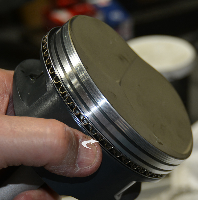
If you are using an oil control ring support rail, it must be installed correctly. The dimple is there to keep the support rail from rotating and the convex side of the dimple faces down to catch the edges of the cutaway where the pin passes through.
It may seem mundane, but preparation begins with a physical count. There’s nothing worse than getting ready to prep eight rings and find you’ve only got seven — or, say, a side rail is missing. After thoroughly cleaning the pistons we verify the piston and ring combination fitment.
Ring sizes, widths, side clearance and back clearances are checked. Side clearance can be measured with a feeler gauge or with gauge pins. If you’re mounting new rings on old pistons during an off-season freshening-up, make sure you monitor the ring groove wear. Grooves tend to open up nearest the bore wall over time, forming a “V†from root to mouth. Back clearance is checked by sticking the ring into the groove backward and rolling it around the circumference of the piston. Oil drain holes behind the oil control ring, oil feed holes into the pin area are checked, and the pistons are marked for skirt-to-bore measurement. Your pistons will come with a card that indicates where on the skirt to measure and it’s important to follow that precisely since piston shapes are irregular due to cam and barrel variation.
Bore cleaning
  |
| These pistons came out of engines during an end-of-season teardown. You can see the minimum contact grooves, also sometimes called anti-detonation grooves because in theory they shield the top ring from the destructive forces of the supersonic shock wave generated by detonation by disrupting wave propagation. You can also see the groove in the land between the top and second ring that’s called an accumulator groove. It’s supposed to provide a little extra volume for the gases that get past the compression ring to vent into so the pressure doesn’t equalize across the ring and cause flutter — looks like it wasn’t needed. What you really are looking at is a top ring that worked really well because there is nearly no color present below the top compression ring. There is a lot of chatter about pressure or vacuum present around the rings and about how rings flutter or unseat during operation. While this might be the case in some applications, it’s clearly not the case here. If this ring unseated, it would have left the piston marked with carbon below the top ring. |
If I’m working with a fresh block and I’ve confirmed that all my bores are within a couple of tenths, I work out of one bore for fit checking. Block prep comes first after machining. I use Dawn dish detergent because it lifts grease and oil so well, and I use hot water and an oversized bore brush that I mount in a drill motor that I drive one direction and then the other, stroking it in and out of the bores for several minutes each. I also presoak a couple of low-lint paper shop towels (available through Cleveland Cotton Products) in WD-40 before starting so that I can wipe right through the water and protect the bore from rust. I don’t know why, but a “green†bore will flash rust in a heartbeat, so I don’t even start blowing it dry, I just wipe through the water and apply the WD-40 to keep the rust from coming up. After block cleaning, I apply WD-40 or Marvel Mystery oil to the gallery brushes and run the galleries to make sure there’s no place for rust to start, and I wipe the bores with MMO or WD-40 until they all wipe perfectly clean on a white, low-lint paper towel.
Fitment
The first ring check I perform is the expander fit. On a racing application with a dry sump or vacuum pump using low or very low-tension oil control rings, I want the expander to lay in the bore with some space between its ends.
The side rails can all be checked at once by stacking them in one bore. Normally, you’ll see oil side rail gaps at something between .015 and .030 in., and they will be consistent from batch to batch. I’ve almost never had to grind one. The top and second rings I purchase are always file-to-fit, and I generally run toward the tight side of the recommended gap range unless it’s a nitrous application.
You must take a great deal of time and care when filing thin rings and rails. Move the ring on the table as close to the grinding wheel as possible, take very little material off at a time and support the ring if need be by using an old standard tension top ring as a support piece under the low-tension ring you’re filing. Make sure to go slowly to control the heat generated by the grinding wheel — you do not want to change ring hardness. Don’t force the ring into the wheel too quickly because you can bend a thin ring if you get in a hurry. Just figure that you’re going to be grinding rings for at least half a day and maybe even a full day, depending on the application and how thin the rings are.
After you file each ring, lightly deburr the sharp corners using a fine diamond file. Do not create a “funnel†at the ring ends, either one that faces in toward the piston or out toward the bore wall. Deburring uses a light touch and you’re only just lightly cleaning the ring ends. They should be smooth and square to each other and when test fit in the bore the ring should be light tight all around the circumference.
Deburr and polish

Pictured is the AL-8 assembly lube used in the ring grooves to prevent microwelding, and on the skirt, and the Quik Seat product for the bore.
When installed on the piston, the rings should freely slip around the groove without sticking. If the rings are not coated or Diamond finished on the sides, I’ll lightly wet sand them with a ring holding fixture on a granite block or piece of plate glass with 2000 grit just to make them slick and smooth on the sides, followed by a good cleaning and a light oiling with WD-40 until installation. Take your time if you’re installing gapless rings as the side rails vary in axial width from as little as .010 in. depending on the ring set, and they can easily be overheated or bent during grinding. Record your end gaps, side clearances, back clearances and piston groove dimensions as well. You’ll need that to modify your next build — possibly reducing end gaps for example — or to monitor parts wear from season to season so you can anticipate when you need to order replacement pistons.
Put ‘em on
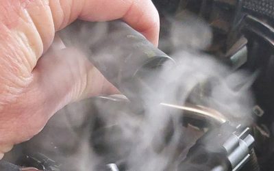
Once the rings are all file-fit, deburred, cleaned, and oiled, it’s time to start prepping the pistons for installation. I start by using a short-bristled paint brush to paint a medium coating of Total Seal’s AL-8 assembly lube into the grooves before I begin mounting my finished rings, and I treat the block with Total Seal’s Quik-Seat dry cylinder wall lubricant.
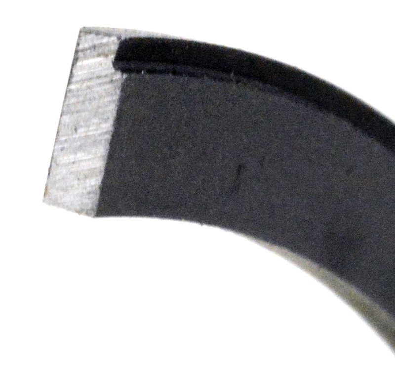
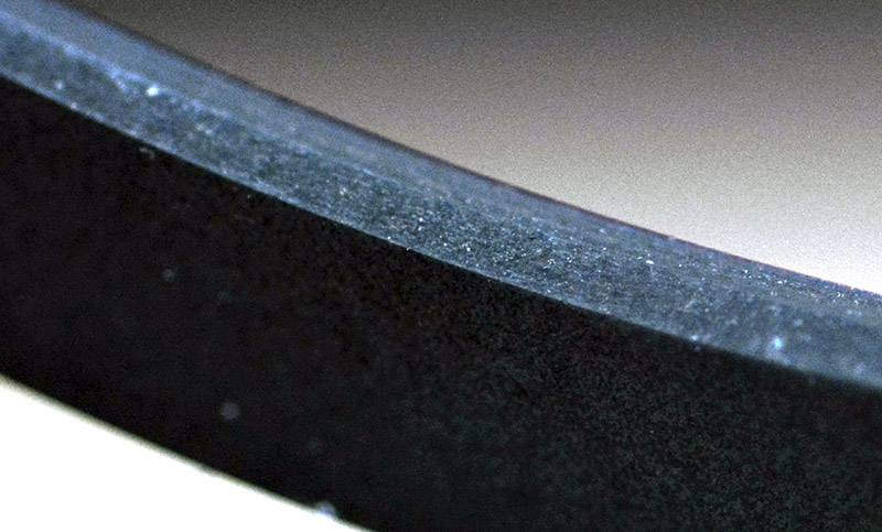
The freshly-filed end of this ring is dressed and ready for cleanup. The Napier profile is clearly visible. The hooked end of the Napier engages the cylinder wall and is used for oil control. While it might be called a second compression ring, that’s a misnomer — it’s really there for fine oil control.
Racing rings, unlike some street sets, do not have a couple of chunks of brightly colored plastic blocking the expander ends to keep you from overlapping them. I guess they’re assuming we’re smart enough to figure out how to avoid that. You’ll find that a fair number of racing pistons with reduced compression height (the distance from the piston pin centerline to the head of the piston) will have so little space between the piston head and pin that the oil control ring groove runs through the pin bore. There are a couple of ways this has been handled; in the past, they used an “Lâ€-shaped button stuck in against the pin to form the missing part of the oil control ring groove, but nowadays we just use a steel oil support rail.
The rail has a dimple that faces down and is positioned in the gap left by the pin boring operation and the oil control ring rests on the support rail. The rail is pretty stiff, so get a good hold on it during installation to avoid scratching the side of the piston up as you put it on. When installing the oil control expander I position the ends opposite the gap formed by the support rail, put my thumb over the ends to prevent overlap, then wind the side rails to space the three gaps 120 degrees apart.
If you are someone who likes to check the oil control tension by using a fish scale to drag-test it through the bore, here’s the correct procedure: Install the piston upside down in a dry bore with just the oil ring installed and pull the piston through the bore with the bore parallel to the floor and record the pounds of pull needed to sustain motion once motion begins, NOT the breakaway pounds reading. I don’t generally check my rings like this. I just record turning torque with all eight pistons installed for each of my builds.
The second ring goes on next, usually a Napier, and if it’s .043 in. or less I can usually just install it by hand, spreading it with my thumbs. Use a ring expander if you lack the hand strength to do that. The top ring follows and I orient the top and bottom gaps 180 degrees apart if I’m running conventional rings. If you’re using a gapless ring, the thin rail always goes down so the main ring can protect it.
Normally, rings are marked with a dot or pip or the word “top†on the ring, but in those rare cases where there are no marks just remember that the inside chamfer of the top ring faces up and the inside chamfer of the second ring faces down 99.99 percent of the time, and the top ring will be the one with a chrome face or moly filling around the outer circumference. Your best option is to lay the rings out on the packaging they came in so you don’t mix them up.
 |
 |
| You can clearly see the differences between Total Seal’s Diamond finished ring and the C33 steel top ring. The Diamond finished ring is very highly polished and the C33 still displays a bit of roughness and some tooling marks. The friction-reducing face coating is seen as a thin gold-colored layer on the ring face. If you’re running anything other than these highly-polished rings, a little wet sanding work with 2000 grit and a piece of place glass will dramatically improve how the ring feels in the groove. You won’t have to touch a Diamond finished ring — you paid them to do the hard work. | |
Put ‘em in

Here’s a .9 mm Napier second ring. It measures .0352 in. and appears considerable smaller and more delicate that the previously-shown .043 in. Napier. Grinding smaller rings is a challenge. You have to minimize the amount of the ring overhanging the table on the ring grinder and in some cases you might use a piece of an old .043 in or 1/16th ring as a support to keep the end of the ring from dancing against the grinding wheel or getting caught and bent down over the edge of the table.
Installation into the bores is accomplished with rod guides and a size-specific tapered bore ring compressor. I like the ones from ARP or Total Seal best as they seem to have the most gradual taper and installation goes more smoothly with them than with some of the others I’ve tried. If you’re using a gapless ring, you only need to make sure that the rail is “clicked†into the “L†ring groove, then center the ring as you insert it into the compressor. Before installing, I paint the skirts with AL-8 assembly lube, install the lubricated upper half of the rod bearing, press the piston home, install the bottom bearing half and rod cap, and roll the engine over to prepare to fill the next bore.
Teardown inspection
Teardown is just as important as assembly because as you relax rod bolts you can check stretch and you can look at the oiled parts, bearings, head gaskets, springs, valve adjustments, and rings to see how everything did that season. Look, if you’ve got a lot of blowby — if you’re pushing oil out of the oil tank or the breathers — that’s a pretty good sign that your rings aren’t getting the job done. Oil consumption and pistons that show a clean edge all around the circumference where the oil wash has cleaned up the piston head are tell-tale signs of a potential ring or bore problem.
You should also look at each piston between the top and second ring. If there’s no combustion color between the rings, guess what? Your compression ring is doing the job. While we call the second ring a compression ring, it’s really just there for oil control. The oil ring handles the gross oil control, the second ring takes care of fine oil control, and the top ring contains combustion pressure. If you’re relying on the second ring for combustion control, you’re in trouble. Make sure you check the ring ends for signs of butting and adjust your end gaps accordingly. If butting was a problem and it was too severe, you’d already have had the engine apart to fix it, but if you see it just shining the ends you might want to add a couple of thousandths to the gap.
Part of racing usually includes producing more power or building an engine with better reliability. Ring seating and sealing is an important part of the formula. Extracting more power during the expansion or power stroke, and increasing the efficiency of the intake and exhaust strokes can both affect the efficiency and tune of the engine. Attention to detail during ring preparation makes all of that possible.
[alert variation=”alert-info”]I’d like to thank Keith Jones of Total Seal Piston Rings for spending quite a bit of his time walking me through some of the newer technology and correcting a few of my bad habits. His contribution cannot be overstated.[/alert]  |
| Once installed, the support rail gap will end up over one of the skirt faces. Install the expander opening on the other skirt 180 degrees from the support rail gap. |
  |
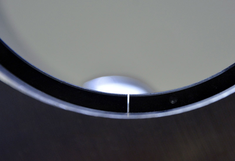
| Here’s a side-by-side comparison of a low-tension expander and a high-tension expander as they sit in their respective bores. As you can clearly see in the high-tension example, its overlapping ends will create more radial pressure once properly butted and installed on the piston. In the low-tension example, the expander doesn’t even come close to touching and in fact there’s clearly space between the bore and the expander. |
The ends of the piston ring must be parallel and the ring must be light-tight in the bore around the entire circumference. After grinding, just lightly deburr the ring ends to remove any sharp edges left from the grinding process.

For all uncoated or Diamond finished top and second rings, I normally spend a little time wet sanding with 2000 paper, a glass or granite plate, and a ring fixture. This is just a few quick strokes to knock down any burrs around the gap and to smooth up the ring faces just a bit. It makes quite a difference in how the ring feels in the groove as you rotate it.

The best and easiest way to check the oil control ring end gaps is to stack them all up with the gaps aligned, and measure them all together. Side rail gaps are normally about .015 to .030 in. They are remarkably consistent from batch to batch, so getting a good reading on them by doing this is pretty easy. Trying to do them one a time is like threading a noodle through a needle — they just twist and flop around all over the place.

Once the end gap is ground and checked, use a fine diamond file to carefully deburr the freshly-ground end. You only want to remove the burrs and sharp edges. You do not want to change the profile of the end of the ring, or put the ends of the rings out of parallel.
 |
 |
| Always, always, always confirm that the expander ends are butted against each other after the side rails are installed. You’d think lapping the ends would be next to impossible to do, but never underestimate folks. You’d be surprised at what determination can get you… | |

The oil control ring expander is what sets ring tension. The side rails are just along for the ride. The corrugated segments collapse slightly as the ring is pushed into the bore and the total radial tension is set by how much or how little overlap the expander had in the bore prior to installation.

When you call to order rings and you ask for “standard-tension 2 mm oil control rings,†understand that that means low tension. The axial width of the ring determines the tension, which is why as rings get thinner they get lower in tension. While an old 3/16th oil control ring might run 22-28 pounds, a 3 mm oil control ring might be down around 10-13 pounds and a 2 mm ring could be around 6-8 pounds. Therefore, asking for a standard-tension 2 mm oil control ring means that you’re going to get a very low tension oil control ring BECAUSE it’s only 2 mm thick. That’s how it works.

Should you buy and use a gapless ring set, there are definite differences between the oil control side rails and the compression rail. The oil control side rail shows a shiny chrome face and it’s a bit thicker axially and radially, although that can depend on the compression rail axial thicknes,s which comes in several thicknesses. The shiny face is the usual giveaway, but just to be sure avoid mixing the rings up during checking and grinding.

It’s not that you can’t do a good job with a hand grinder, it just that it takes you all day to do it. This unit from ABS has a table that the ring is clamped to and a dial indicator to help you get the exact end gap you need. If you do use a hand ring grinder, don’t make the common mistake of trying to grind both ring faces at the same time. One face at a time, please, take your time, and keep the ends square.

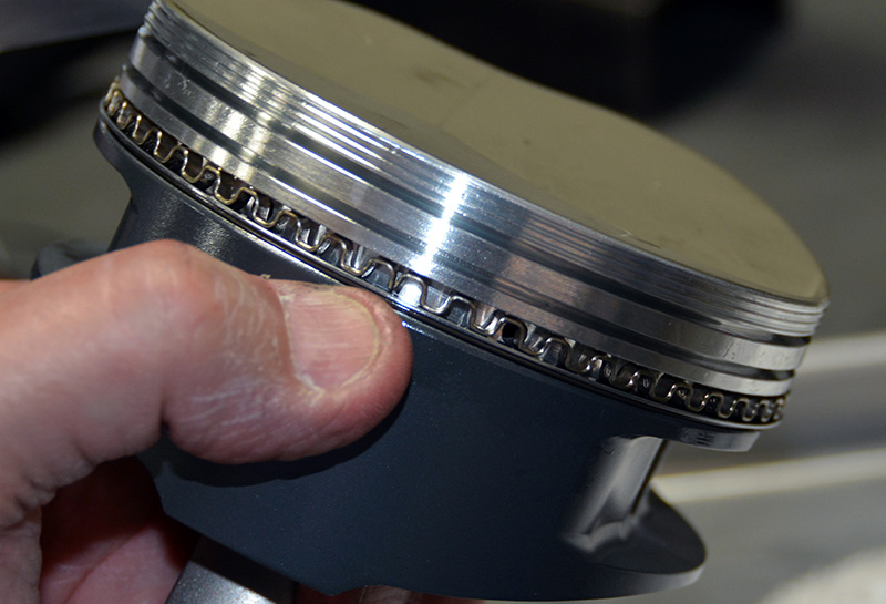
With the support rail in place, wind the expander onto the piston and butt the ends. Then, place your thumb over the butted ends to keep them from overlapping each other as you wind the lower oil control side rail ring in place. Once you get one side rail on, you won’t have too much to worry about.
The inside diameter of a ring may or may not be chamfered. If it is, the chamfer of the top ring faces up in the groove and the chamfer of the second ring faces down in the groove unless marked otherwise. I’ve never seen a ring marked contrary to this rule, but that doesn’t mean that it can’t happen. Normally, rings will have a dot or the word “top†on the rail near the gap opening.

0 Comments