
Determining if a fuel injector is the cause of a problem can be difficult. An injector can cause symptoms ranging from a slight decrease in efficiency and emissions to a total misfire. Here’s how fuel injectors work, how to test them for failure, and some diagnostics that can save time.
 Fuel injectors are generally problem-free, but when something does go wrong, you need to be able to diagnose them quickly and efficiently. This is not difficult on some engines, but others have little or no easy access to the injectors. In these cases, hours can be spent just to access the injectors. If it turns out that there is an injector problem, the time spent accessing the injectors is just part of the repair. But if there is no injector problem, the hours of time have been wasted, and wasted time is wasted money.

This is a cross-section of a typical fuel injector. Designs vary by application, but all port fuel injectors contain these components. Spray pattern is determined by the size, shape, and number of perforations in the perforation disc located at the bottom of the injector.
First, let’s take a look at how a modern fuel injector works. It’s a solenoid valve consisting of a coil and a needle valve (pintle) contained inside a plastic or metal housing. Two wires go to each fuel injector. The first wire will be the same color for all the injectors, and will have battery voltage present any time the key is on. The second wire will be unique to each sensor. This is the ground wire, and is controlled by the ECM. The amount of time the injector is grounded, measured in milliseconds, determines the amount of fuel that passes through the injector. When the injector coil is energized, a magnetic field is generated that pulls the pintle open. This allows fuel to pass through the injector into the intake port and, ultimately, the cylinder. Fuel enters through an orifice on the top of the injector. It passes through a screen filter, the body of the injector, and then through the perforated disc at the bottom of the injector. The screen filter keeps any particles that were too small to be caught in the fuel pump filter out of the fuel injector. The perforated disc determines the spray pattern of the fuel.
Any debris that passes through the screen filter will cause problems in the injector. Either it will hold the injector open, causing fuel to pass through it when closed, or it will clog the injector, causing less fuel to pass through it than desired when open. Both of these issues will confuse the ECM, and it will try to compensate by adjusting the time the injectors are open.
The ECM is programmed with base fuel maps, which determine how much fuel should be delivered for any given engine condition. These base maps are calculated by engineers and are based on computer models of engine requirements. They are a good baseline for fuel delivery, but in the real world, conditions aren’t always the same. Changes in things as simple as humidity can affect the combustion process. So the ECM has to be able to adjust fuel injector pulse duration to keep the engine running as efficiently as possible.
These adjustments are called fuel trim. There are two types of fuel trim implemented in modern fuel injection systems: short term fuel trim, and long term fuel trim. Short term fuel trim refers to the constant, small changes the ECM makes in pulse duration. It is based on air/fuel ratio sensor feedback. The ECM tries to keep the fuel to air to fuel ratio as close to 14.7:1 (stoichiometric) as possible. Long term fuel trim refers to more permanent changes in fuel delivery that are based on the patterns of the short term fuel trim, usually due to engine wear. If the ECM sees consistently positive or negative fuel trims, it gradually adjusts the long term fuel trim to compensate. Long term fuel trim sets a new baseline for short term fuel trim.
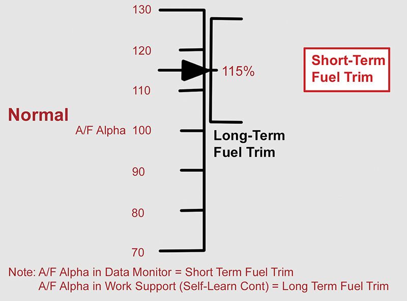
Here we see an A/F Alpha of 115%. This indicates the A/F Ratio Sensor detects a lean condition, and the PCM is increasing injector pulse duration by 15% to compensate.
Nissan’s measurement PID when using the CONSULT III plus for both fuel trims is called “A/F Alphaâ€. While in the Data Monitor screen, A/F Alpha represents short term fuel trim. While in the Work Support screen, A/F Alpha represents long term fuel trim. A value of 100 means there is no deviation from base fuel mapping. A value above 100 indicates the engine is running lean, and the ECM must deliver more fuel to maintain the stoichiometric ratio. A value below 100 indicates the engine is running rich, and the ECM must deliver less fuel to maintain the stoichiometric ratio. A/F Alpha can range from 75-125. Beyond that range, the ECM assumes there is a problem, and sets either a P0171 or a P0172 trouble code.
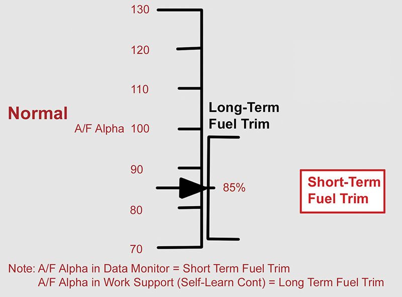
Here we see an A/F Alpha of 85%. This indicated the A/F Ratio Sensor detects a rich condition, and the PCM is decreasing injector pulse duration by 15% to compensate
The fuel injection system is one of the most complex systems in any modern vehicle. It analyzes input from just about every sensor in the vehicle when determining the proper amount of fuel to deliver to the cylinder. The amount of fuel delivered to the cylinder is determined by two things: fuel pressure and injector pulse duration. Fuel pressure may vary, depending on engine load, but always in a predetermined value. Therefore, the only way to differ the amount of fuel entering the cylinder is by varying the pulse duration of the injector. A longer pulse duration holds the injector pintle open longer, allowing more fuel to pass through it. A shorter pulse duration allows less fuel to pass through the injector.
The most common problems involving fuel injectors are the engine running rich, the engine running lean, or single cylinder misfire. There are many different factors that can cause these problems, and because fuel injectors are often very difficult to access, they tend to be tested last. The most easily accessible items should always be tested first. Usually these are components like mass airflow sensor, ignition coils, and spark plugs. Once these components have been tested and ruled out as the cause of the failure, the injectors should be addressed.
Testing Fuel Injectors
After you have determined that the injectors are likely the problem, you need to begin testing them. The first test is simple, straightforward, and requires only a stethoscope and a well-trained ear. With the engine idling, use the stethoscope to listen to each fuel injector. If a stethoscope is not available, a long screwdriver will work, but it is not ideal. What you want to hear is the injectors clicking evenly and consistently. The main purpose of this test is to identify an injector that sounds different than the rest, and any discrepancies can indicate failures. If an injector sounds different than the rest, you should focus further testing on that injector. Keep in mind that even if all the injectors click evenly, there may still be a problem. This test is meant to be a quick check for obvious problems, not a definitive indication of injector health.
The next logical step in testing fuel injectors is also quick and easy, but does require a CONSULT III plus. It is called a power balance test, and is invaluable for identifying how much power each individual cylinder is contributing to the overall performance of the engine. With the CONSULT III plus connected to the vehicle, select the Engine option, then Active Test, then Power Balance. As each cylinder is deactivated, you will see a drop in RPM. The service manual simply says that each cylinder should produce a momentary drop in engine RPM. While this is true, it is not the main benefit from this test. The most useful feature of the power balance test is the measurement of the RPM drop for each deactivated cylinder. Ideally, all cylinders would drop an equal number of RPM when deactivated. In reality, they will never drop the exact same RPM, but they should all be within 10% of each other. Remember that a high RPM drop indicates a strong cylinder, and a low RPM drop indicates a weak cylinder. If a cylinder drops much less RPM than the others, then it should be addressed further. Specifications vary, depending on the engine and application, so be sure to refer to the service manual before condemning any components.
Another very useful, but not definitive, way to test a fuel injector is a resistance check of the injector’s coil windings. This check, as with the previously discussed tests, can identify a failed injector, but does not guarantee a good injector. If the fuel injector connector is easily accessible, simply connect an ohmmeter across the terminals to measure the resistance. Specifications vary by application, but generally, the internal resistance should be between 10 and 15 ohms. An injector winding with high resistance, low resistance, or an open will cause the injector to operate improperly, but it is also very common to see internal resistance within specification on a failed injector. This test simply checks the integrity of the coil windings, and has no bearing on the condition of the rest of the injector.
Some engine configurations make accessing the fuel injector connectors very difficult. In these situations, resistance testing should be done from the most accessible connector available. This may be a sub-harness connector for some vehicles, but most Nissan vehicles place the ECM in an easily accessible area of the engine compartment. Take advantage of this, and use a pin diagram in the service manual to locate the appropriate wire to connect to.

This is a fuel injector voltage and amperage trace on an oscilloscope. Voltage is steady around 14V until the injector is commanded ON, at which point it drops near 0V. Voltage spikes when the injector is commanded OFF due to the collapsing magnetic field. Amperage steadily increases as soon as the injector is ON. The slight drop in amperage, circled in green, indicates the injector pintle is opening. If you do not see this “gallâ€, the injector pintle is stuck.
All of these tests can identify a failed fuel injector, and they often will. However, sometimes you have to delve deeper into investigating the source of the problem. One of the most useful and informative tests involves looking at the voltage and amperage waveforms of each individual injector. Performing this test requires an oscilloscope. As with the resistance test, connect the oscilloscope leads to the most accessible connection. It may take a few minutes to get the scope set to the proper parameters to be able to see the injector waveform, but once it is set up, you can assess each injector fairly quickly.
What you should see, is steady battery voltage up to the moment the injector is commanded open. At this point, the voltage will drop near zero as current flows through the circuit. Voltage will remain near zero for the duration of the injector pulse, after which there will be a large voltage spike. This voltage spike is caused by the magnetic field collapsing when the ground is terminated.
You should focus on amperage when attempting to identify a stuck injector pintle. The amperage will be zero up to the point that the ECM grounds the circuit. It will then steadily climb to the point where the injector pintle begins to move. At this point there will be a subtle dip in amperage due to the movement of the pintle inside the magnetic field. Following the dip, amperage will continue to rise steadily until the ground is terminated, and then drop quickly back to zero. This dip in amperage is what you are looking for, and if you don’t see it, the injector pintle is stuck. It takes some practice to identify, so be sure to produce an amperage graph from each injector and compare them carefully. Replace any injector that does not produce this dip in amperage.
If an injector passes all the tests mentioned above, there is a final test that is the most definitive in identifying fuel injector condition. However, it is also the most time consuming. The test is set up by removing the injectors from the intake manifold, but keeping them connected to the fuel rail, and placing each injector in a suitable container like a glass jar. Each fuel injector is secured to the fuel rail by means of a metal clip. This is convenient, as the injectors can be cycled while they are removed from the manifold, but will still stay connected to the fuel rail.
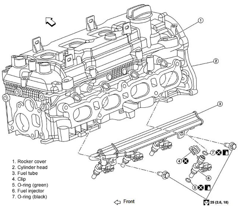
This is an illustration of the fuel injectors and fuel tube (fuel rail) on the QR25DE engine. Notice the clips (#4 in this picture) that hold each injector to the tube. This allows us to cycle the injectors away from the engine without them ejecting from the tube.
Before the injectors are set up in their containers, the ignition system needs to be disabled. Usually, the easiest way to achieve this is by removing the electrical connectors from each ignition coil. After this is done, crank the engine and observe the spray pattern of each injector. They all should produce an even amount of fuel in an identical spray pattern. Replace any injector that is not flowing a proper amount of fuel, or has an abnormal spray pattern.
As you can see, there are many different tests to determine the condition of fuel injectors. They range from quick and easy tests that can take only minutes, to in depth, time consuming tests that may take hours. Always keep in mind that the fuel injection system is perhaps the most complex system implemented in modern engines, and its operation depends on input from many different sensors. In many cases, the fuel injectors themselves are not the cause of the malfunction. Either the ECM is receiving poor data from one or more sensors, or there is a problem with the fuel injection electrical circuit that results in incorrect voltage being applied to the injectors.
Considering all the work that is often required to access the fuel injectors themselves, be sure you are confident that all supporting systems are in good condition before starting complex, time consuming tests of the fuel injectors. Prioritize repairs based on both time required to test, and by the probability of component failure.


0 Comments