

Greg gives us a completely different take on the argument between fans of carburetors and those of fuel injection, plus some historical perspective and great hands-on tips. Everybody should read this.
As carbs give way to fuel injection, a whole generation of racers is missing out on the physics lessons to be learned from old-fashioned atmospheric fuel delivery systems. Simple isn’t always bad and complicated isn’t always good!
Carbs work 100% of the time as long as there’s atmospheric pressure, fuel supplied at proper volume, and pressure and air moving through the venturi. Something else to consider is that, at least as of this writing, for the most part highly-evolved carbs such as the Holley 4150 and Holley Dominators do a better job at atomization than injection does. As one fuel injection expert once said, “When they make a fuel injection system work as well as a carburetor, they’ll call it… a carburetor!†High-pressure fuel pushed through a small orifice tends to form streams and larger droplets than a fully-developed race carb with the latest boost nozzle, skirting, and metering systems installed. Will this change with evolving technology and improved manufacturing? You bet — it always does!
Room to Grow
One big advantage of injection is that since it’s a relatively immature technology in the racing world there’s lots of room for innovation and improvements, improvements we are already witnessing with the port and throttle body racing systems that are on the market today. Where racing injection really shines is under boost conditions. Being able to inject fuel into a pressurized inlet system, tune fuel pressure and volume in combination with the flexibility to design systems that use eight, 16, or even 24 injectors of different flow rates into different points in the intake to tune to the increased oxygen supplied by a supercharger is another huge advantage. Supercharging fixes all kinds of problems when compared to natural aspiration. The “fill-it-up†problem is replaced with an “empty-it-out†problem, and forced inlet flow eliminates a lot of inherent port flow issues associated with natural aspiration. With natural, you have to coax or finesse the air into the cylinder; with a supercharger you just stuff it into the bores. With proper cam and intake-to-exhaust valve ratio selection, a careful builder can make enough reliable power with boost that the limit becomes the physical structure of the engine hard parts. The suppliers of those parts are answering the call with some very robust bits designed to handle the power levels fuel injected, supercharged engines are capable of producing.
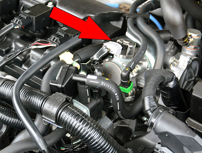
High pressure fuel pump system; direct injection engine 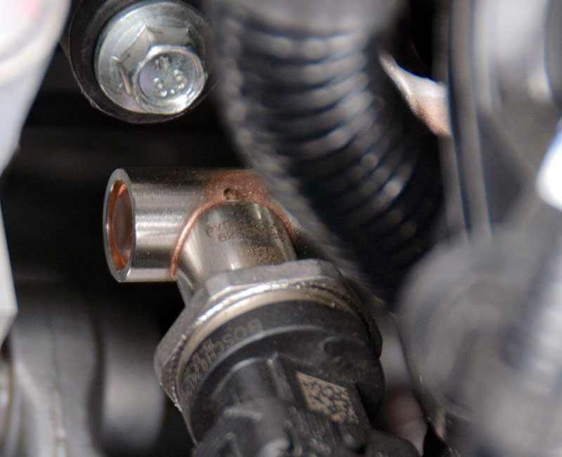
The fuel rail is substantial and buried. You can just make out the end of it.
The other development to watch is that the latest mass-produced gasoline EFI systems are now direct injection — gasoline is injected right into the sealed combustion chamber at high pressure, just like in a diesel engine. Manufacturers are taking advantage of highly-tunable, variable valve timing systems and reliable, very high pressure fuel delivery pumps (in excess of 2,000 psi) and either high-voltage, high-amperage conventional injectors, or piezo-electric, low-hysteresis high-pressure fuel injectors. By the way, be aware of the fact that some of these systems, running at as much as 90 volts and 10 amps, can kill you. Make sure you know what you’re working with BEFORE you touch it!
Direct gas injection has been lurking in the shadows for decades, but rapid advances in manufacturing, quality, and durability are pushing it out into the mainstream. As this technology gains wider acceptance it will likely make its way into the world of high performance as racing parts manufacturers find ways to improve on the original designs.
The biggest advantage of direct gasoline fuel injection systems is that they manage air and fuel independently, with air controls completely dry and the fuel injected at high pressure directly into the combustion chamber at or near the end of the compression stroke, just like in it’s oil-burning counterpart. Incoming air volumes are better managed because you don’t take up intake volume with fuel and you don’t have to worry about fuel falling out of suspension as it negotiates intake manifold turns. You can make the ports right-sized to better manage intake side air velocity since you don’t need enough port volume to handle wet flow, plus you can install air control flaps and valve systems to adjust and tune intake runner effective lengths and volumes because there’s no liquid or vapor in the inlet flow to be stripped by sudden changes in air direction.
With fuel delivered directly to the combustion chamber, you can precisely control the timing and amount of fuel introduced, keep the fuel cooler, longer, and use the wet, cold fuel to cool the combustion chamber, which helps reduce detonation. This fuel delivery system, combined with high static compression ratios and widely variable intake and exhaust valve timing systems, are bringing modified Atkinson cycle engines to the masses from virtually all the manufacturers right now. One manufacturer using this technology has a naturally-aspirated 2.5L engine running a 13:1 static compression ratio that develops 184 horsepower on 87 octane fuel. That’s 1.2 horsepower per cubic inch out of a buy-it-off-the-showroom-floor non-turbo 3,600 pound grocery-getter that also happens to score over 25 miles per gallon in the city. Don’t think there’s not a ton of room for performance enhancements in a larger displacement version of that kind of technology.
Fundamentals
Holley flats align with seat window 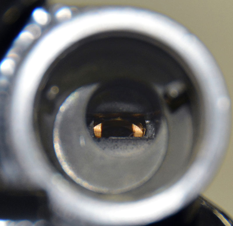
Holley fuel path needle and seat align.
Now that we’ve talked about the future, let’s travel back and take a look at the technology that most weekend warriors still run — the humble carburetor.
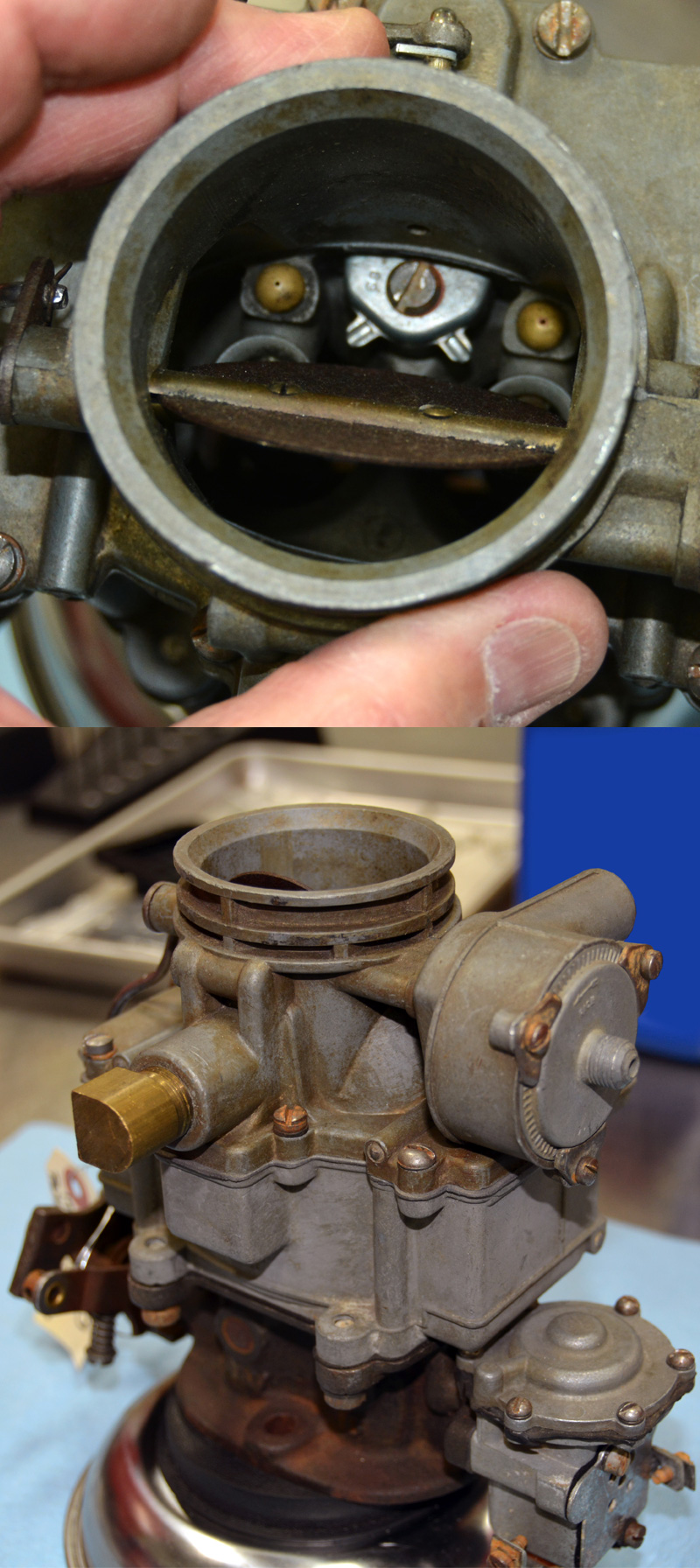
The modern carburetor (or not so modern, for that matter) uses seven circuits to start and control air and fuel ratio from start up to warm up, from idle to full throttle. Each of these systems has subsystem components that can be refined, modified, and designed to improve the performance potential of your little die-cast fuel mixer. The seven circuits are:
- Float, bowl, and fuel level control parts
- Choke, starting, and cold enrichment system
- Accelerator pump system
- Power enrichment circuit
- Idle circuit
- Transfer or transition circuit
- Main circuit
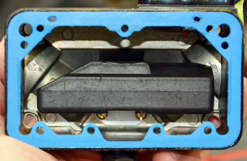
Holley foam float adjustment 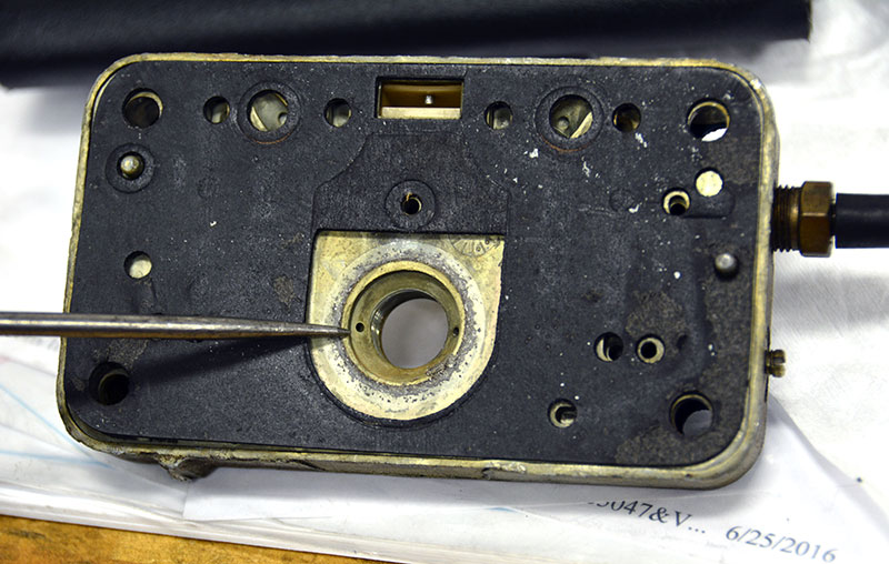
Black gasket and the power valve restrictor channel.
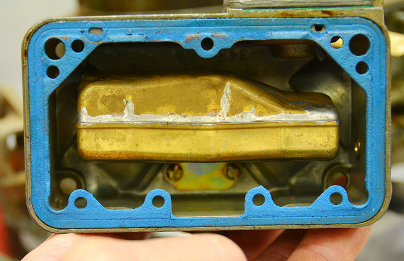
Let’s take them in order from the top. The float and bowl and fuel level control system is everything between the fuel line and the bowl, which is where a reservoir of fuel is kept inside the carb body. You need to have a quantity of fuel in the carb to keep the jets and fuel pickup points covered when the engine is running and under all conditions of acceleration, turning, and deceleration. You also require a quick source of fuel available to get her running. If the bowl leaks off, then you might have to crank the engine for longer than acceptable just to get it to start.
The system includes the inlet nut and path up to the needle and seat. Everything has to be sized and shaped correctly to get all the flow you need at full power without upsetting the liquid enough to risk losing control of it. Something to remember about automotive fuels like gas or methanol: If you put a sharp edge in the flow path and pull a high volume of fuel past that sharp edge, you’ll induce foaming in the fuel stream, and foam is impossible to control. Foaming dramatically increases the fuel’s apparent volume and since it’s largely vapor it won’t provide the buoyancy needed to keep the float lifted, which means the incoming fuel can’t be controlled, spilling out all over the top of the engine and creating a fire hazard. Fuel volatility, high under-hood or ambient temperatures, fuel line proximity to hot exhaust, and poorly-shaped fuel handling components all add to the possible loss of control.
Quadrajet fuel path. 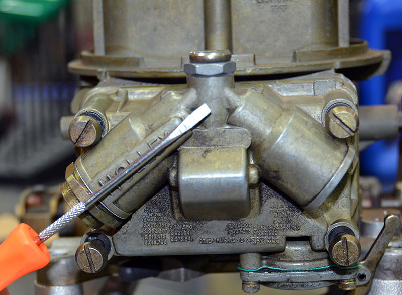
Holley fuel path. 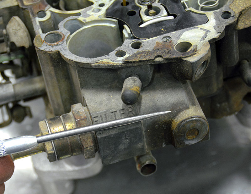
Quadrajet fuel path. 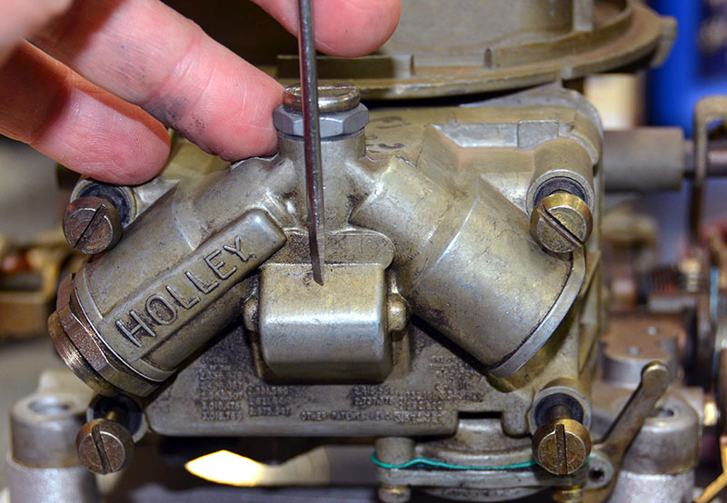
Holley fuel path; one 135 degree turn 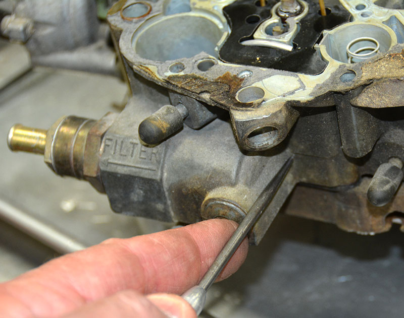
Quadrajet fuel path. 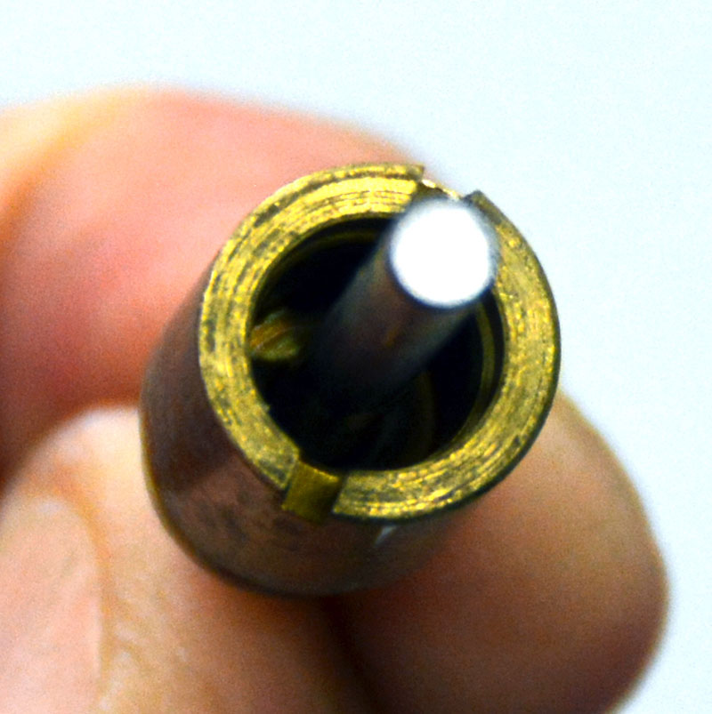
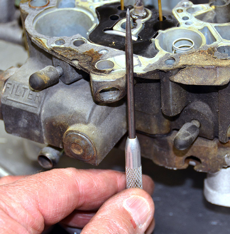
Rochester quadrajet seat measures .130in from bottom feed
By comparison, the fuel path on the Quadrajet is more convoluted. Fuel must make three 90-degree turns to make it to the needle. Where the Holley feeds from the top, the Q-jet feeds from the bottom. I sized the Q-jet seat with a gauge pin measuring .130 in. In a few cases “back in the day,†the Quadrajet was used in a mild performance applications, but it was mainly designed to provide great throttle response and reasonable fuel economy in a four barrel design, something most would agree that it did with a minimum of fuss and maintenance.
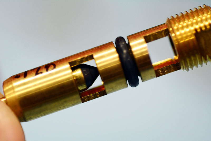
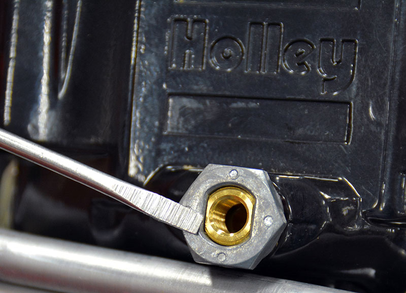
In our 4150, the fuel inlet bore is roughly .270 in. through the fuel inlet nut, which is typically fed by a 3/8 in. line. From there we pass up to the needle and seat area, where an annular opening surrounds the seat assembly, which seals to the bowl body with an “Oâ€-ring on the bottom side. When installing the seat into the bowl, a touch of Vaseline helps to prevent tearing the “Oâ€-rings. The float level adjusting nut and lock screw are sealed with thin paper gaskets to keep the fuel where it belongs on the top side of the needle assembly. I usually apply a little Vaseline to those gaskets to keep them from tearing from future adjustment work — it seems to help.
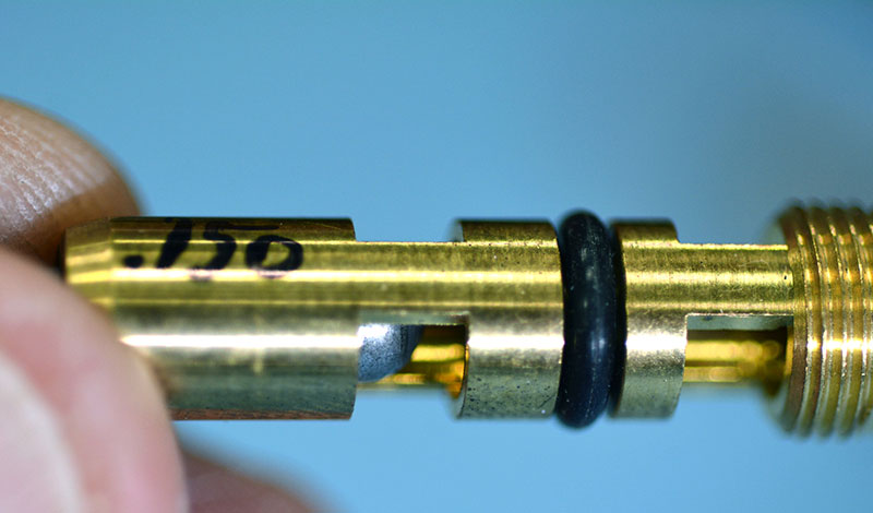
After passing through a pair of slots in the seat assembly, the fuel makes a 135-degree turn downward and passes through the needle and seat assembly, and these, like nearly everything on the Holley carb, are tunable. You’ll find Holley needles and seats in the following sizes and materials: In Viton in .097 in., .110 in., .120 in., .130 in; in steel in .097 in., .110 in., .120 in., .130 in., .150 in.; in titanium .150 in. Steel and titanium would primarily be used for methanol. Why titanium? For the same reason we always use lighter materials throughout engineering — less mass translates into faster response times in dynamic systems.
Floats are available in both brass and sealed foam. Brass is heavy, tends to react more slowly to changing fuel levels, has been known to collapse inward under extreme temperature changes (or with a carb fire), and can also develop leaks and sink. On some applications, brass will interfere with secondary metering plate systems, so make sure you read application and installation instructions carefully before changing from brass to foam or vice versa. Brass is largely no longer the first choice for most carb builders. Nitrophyl floats are available notched for use with jet extensions in the secondary bowl and wedged for circle track use and un-wedged for the straight-line racer. The wedge allows the bowl level to rise up the outside wall in turns without shutting off the needle and seat.
Setting the float level dry is simple. Just invert the bowl and set the flat top of the float parallel to the flat top of the bowl cavity using the screw bosses as a reference. If there are permanently installed windows just center the fuel level in the window, and if there are level checking screws just remove them — carefully! — on a running engine (making sure to have rags available for spilling), and adjust the level until the fuel just dribbles out of the screw hole. There are temporary plastic windows that seal with an O-ring you can install in the screw hole, but I’ve not had a great deal of luck using them. They’re too small and nearly opaque — I can’t really see through them that well. The beauty of the Holley carb is that it’s so well designed that it’s simple and field tunable by someone with just a little skill and a desire to learn.
Speaking of tuned, stay tuned. We will continue to examine our little fuel mixer and cover some in-the-bay and at-the-track quick adjustments and adjustment tricks, and we’ll also continue working our way through the seven circuits and systems so you’ll have a good working knowledge of how to fix any carb problem you encounter. It’s a dying art and one that might provide you with a source of income as more of us old guys head out to pasture.
Steel needle – .150-in. seat 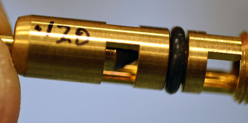
Viton needle and seat – .120-in. 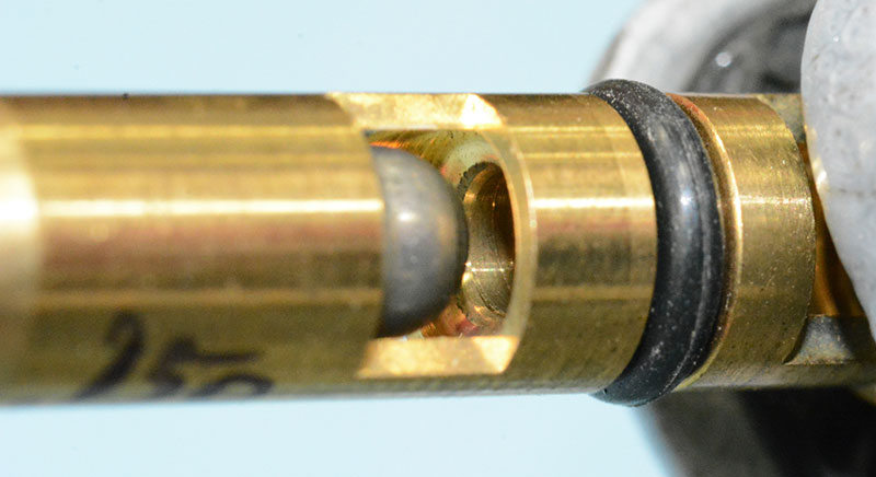
Steel needle – .150-in.; seat number two 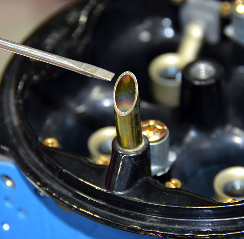
There must be a vent for fuel to flow into a fuel bowl.
What the Heck is Atkinson-Cycle Again?
As used today, Atkinson-cycle describes an Otto-cycle engine in which the intake valve is held open longer than normal during valve closing to reduce the dynamic compression ratio and therefore lower the peak compression pressure as seen on a compression gauge while holding the exhaust valve closed as long as possible to maximize work extraction.
This strategy reduces the work required to compress the charge, but allows a longer power duration period because the exhaust valve is held closed longer. It’s a low dynamic compression ratio, high expansion ratio engine. In its most effective form it increases efficiency and fuel economy, but not without a potential downside.
Since power production is dependent on the mass reacted, holding the intake off the seat for a longer period of time also reduces the total amount of trapped mass that is available to burn to create heat. Holding the intake valve open longer also increases the risk of reversion (shoving air or air-fuel back up into the intake manifold) thus creating violent intake pulsations that would disturb adjacent cylinder flow and also lower intake manifold vacuum. Modern dry manifold direct injected gas engines don’t suffer as much as their wet intake brethren since they only manage air in the intake, and lowered intake manifold vacuum reduces pumping losses, which only adds to the efficiency of the design.
The disadvantage of a standard (non-variable valve timing engine) four-stroke Atkinson-cycle engine versus an Otto-cycle engine is reduced power density, but, this disadvantage disappears with modern variable valve timing systems. In days gone by, four-stroke engines of this type that use the same type of intake valve motion used a supercharger to make up for the loss of power density and were known as Miller-cycle engines.
Hysteresis?
In an electrical circuit things don’t always happen at the speed of light, as the theory would dictate. Excessive capacitance, inductance, resistance, or the physical properties of the materials used to conduct electricity or commanded to actuate may contribute to a delay, either as energized or engaged, or while being de-energized or disengaged.
It’s a big word for system lag, and it accounts for a number of design or physical attributes that the various elements of the circuit may possess. There are times when it’s good (the magnetic strip on your credit card) and times when it works against your design criteria and must be fixed, or at least accounted for. Hysteresis exists in electrical, physical, and conceptual systems and it’s a word used to explain a built-in delay between the time an operation is requested and the actual time the operation proceeds.


0 Comments