The permanent-magnet generator is pretty much gone, but so is the dedicated voltage regulator.
Think of the battery and charging system as a team. The battery works alone to supply the electrical power to the starter motor and ignition system so you can fire up the engine, plus the juice to operate the power windows, door locks, the radio, etc. Once the engine is running, the charging system provides 14.2V or so to keep the battery up.
The battery also is used to supply extra momentary power that is needed when the electrical demands exceed the output of the charging system, such as when you operate a hydraulic suspension system. When you consider how many electric components such as high-energy electronic ignition, electric fuel pumps and radiator cooling fans, entertainment systems with high-power amplifiers, and on and on, there is a lot more electrical power demand on the charging system than can be satisfied by the capacity that was designed into most pre-1980s vintage vehicles.
If you’re working on such a vintage vehicle that has an aftermarket electronic ignition conversion system, including the units that are used to convert a distributor that had contact points over to solid state, you should know that some of these electronic ignition systems will not operate properly if the voltage falls below 12V. The original wiring harness of many point-type ignition-equipped vehicles often usually had a ballast resistor to lower the voltage to the ignition coil and extend the life of the contact points (there’s a bypass circuit around this resistor that boosts the spark while the engine is being cranked). In most cases, you should remove the ballast resistor when you convert the vehicle over to electronic ignition.
Chicken or egg?
Most vehicles are said to have a 12V system, but this is somewhat misleading. First, any lead-acid wet cell produces 2.1V, so a regular six-cell battery should read 12.6V. Then, as already mentioned, the charging system will generally produce about 14.2 volts when the engine is running. And here’s where the old riddle, “Which came first, the chicken or the egg?†seems to apply. The battery will go dead if the alternator doesn’t replenish its charge, but the alternator can’t produce current unless its field is energized by the battery. Actually, the alternator’s real job is keeping the battery up — that’s why the heavy wire on the back of it is labeled “B.†Also, all the accessories get their power from the battery’s positive post, not the alternator stud. This is, however, a moot point. If the alternator can’t keep up with the draw, it’s all going downhill.
The output current of an alternator varies both by the design and the rpm at which it is driven as determined by the speed of the engine and the ratio between the diameters of the pulleys. Some have a lot of output, but only at high speeds, while others may put out a large amount of current at idle. So, it would be wise to figure out how much current is required to cover everything from the cooling fans to the entertainment system at slow engine speed, then select a charging system that matches or exceeds those needs, and make sure the wires are of a large enough gauge to assure that current won’t be lost in the form of heat.
PCM field control
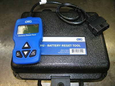
A set charging system voltage of 14.2 will keep a fresh battery fully charged, but the voltage necessary for proper charging increases as a battery gets old, so its life won’t be as long as it could be if the charging voltage were tailored to its aging condition. Therefore, just about all modern vehicles use the PCM (Powertrain Control Module) to regulate the field circuit and compensate for a weakening battery by keeping it fully charged even if that sometimes takes 15.2V, then it sets a charging rate that is often in the 13.5 volt range once there’s a full charge. The computer takes temperature into account, too. This modern technology is a good thing, but when you replace the battery on these new vehicles the PCM will need to be reset so it can go back to the lower charging voltage needed for a new battery.
If you’re going to transplant a modern computer-controlled fuel-injected engine package into a vintage vehicle, you should be aware of the above — there may be no dedicated voltage regulator either inside the alternator, or mounted remotely, since the PCM performs this function. The PCM calculates how much electrical current will be needed by all the electrical components on the vehicle.
Belts and alignment
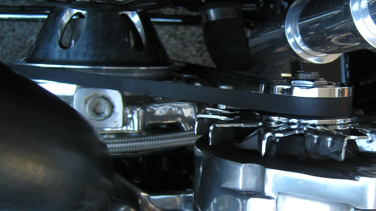
We often see vintage vehicles with the original V-belts slipping and pulley alignment issues. When you combine a high-output alternator with aluminum or chrome pulleys, it is very common to have belt slippage or fan belt squealing issues. A common indicator of belt slippage is that the pulley on the alternator has become discolored from the heat slippage causes.
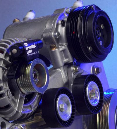
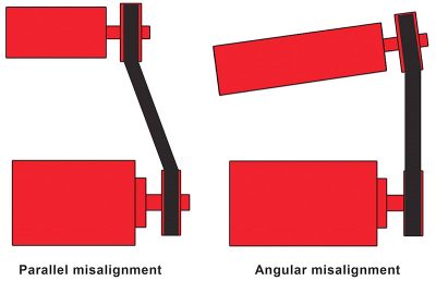
If the engine is throwing fan belts, look for alignment problems, Gates Rubber Company offers a tool that uses a laser to allow the technician to check pulley alignment. If the pulleys do not line up properly with each other, the engine can throw the belt at high rpm, plus the belt will wear out quickly. Proper fan belt fit (the fan belt can be either too wide or too narrow for the groove of the pulley) is important because when it’s not correct it will reduce the contact area and lead to belt slippage problems. If belt tension is too low, it can cause slip, but if it’s too tight it can destroy the bearings in the alternator to fail and shorten belt life.
High-output
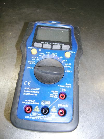
The charging system must be capable of providing enough power to both keep the battery charged and cover the demands of all the electronic systems used in the vehicle at any engine speed or vehicle operating condition. Sometimes this is easier said than done, but with the help of a good electrical shop you should be able to come up with a charging system that matches the needs of almost any vehicle. We have often used custom-built alternators that have reduced air gaps between the stator and rotor so that more amperage will be produced at lower rpm. There are a lot of high-output alternators on the market to choose from, so select the one that has enough output at the engine speeds that your application needs. You can use a ammeter to see how much current is being used when you have the cooling fans, headlights, entertainment system, A/C, and all the other normal electric and electronic systems on at idle, then find an alternator that meets or exceeds that demand.
If the alternator does not have enough current output to cover the demands of all electrical components used on the vehicle at idle speed, you can either change the pulley size on the alternator to speed it up, or install an alternator that has more output at low rpm. The typical pulley ratio most production vehicles used is 3:1 (three alternator revolutions to one engine revolution), but you can usually install a smaller pulley on the alternator to speed it up, but the maximum recommended rpm for most alternators is 18,000. Also, if you’re using an old-fashioned “V†belt, there are limits to how small the pulley can be because that type of belt can only bend so far — that’s one of the advantages of modern flat multi-â€V†belts.
Whenever you increase the current output from the alternator, be aware that a proper cooling fan is critical. Alternator fans are designed to turn in one direction, so if you have converted the engine from “V†belts to a serpentine system be sure the fan is designed to work with the resulting rotation of the alternator to avoid overheating the internal parts of the alternator. Since many of today’s vehicles have so many electric power accessories the output from the charging system approaches 200 amps, some late-model high-output alternators are using engine coolant to carry heat out of the alternator, and/or adding extra heat sinks.
Grounds, grounds, grounds
The positive/power side of the voltage connection to any electrical component is not the only part of the supply circuit that can create problems. Poor negative/ground connections can often be the source of frustrating electrical problems. Good grounds for the engine, battery, each electrical component, and the alternator are vital. Among the many ground connection problems we have seen:
A powder-coated alternator and mounting brackets, which were insulated from a good ground connection by the coating.
A vehicle with such a bad engine ground connection that the braided stainless-steel throttle cable was glowing cherry red since it was acting as the negative connection from the engine to the vehicle’s frame.
A street rod with a fiberglass dash board that provided no ground connections for the gauges, etc.
NOTE: There should be zero voltage drop, as read with a voltmeter, between the negative/ground side connection of every electrical component and the negative post of the battery.
In the next installment, we’ll look at retrofitting electronic ignition, wire size, and voltage spikes.


0 Comments