
An overview of the onboard charging system as well as some tips you may be able to use for your next diagnosis and repair.
Hybrid vehicle performance is best measured in miles per gallon rather than horsepower and torque. The primary benefit of a Toyota hybrid is great fuel economy without the need to drive a tiny underpowered vehicle.
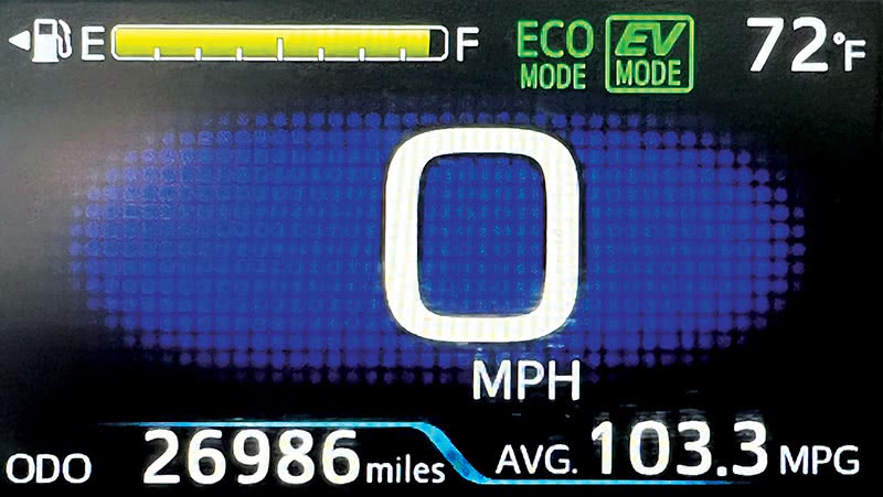
But what if 52 MPG from a full-size car isn’t good enough? What if you want a car that can get over 100 MPG in real world driving? A plug-in hybrid allows you to top off with electricity at less than half the cost of gasoline! And unlike an electric car, there’s no range anxiety. When the fuel level is low after 600 miles of driving, stop at a gas station and drive another 600 miles.
The largest differences between a plug-in hybrid and a regular hybrid are the battery capacity and the onboard charger. Many technicians already have a pretty good handle on battery diagnosis but aren’t as familiar with how onboard charging works. In this article, we’ll give you an overview of the onboard charging system, as well as some tips you may be able to use for your next diagnosis and repair.
Overview
Components of the Plug-In Charging System (2010-2015 Prius PHV)
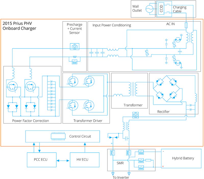
Onboard Charger – This unit filters AC power, performs power factor correction for increased efficiency, boosts the incoming AC voltage, and rectifies the voltage to DC to charge the battery. The Plug-In Charge Control ECU controls its output.
Plug-in Charge Control ECU (PCC ECU) – This control unit controls the onboard charger, monitors charging-related inputs, lights the charging indicator, and communicates with the Power Management
ECU (HV ECU).
HV Battery Junction Block Assembly (SMRs) – This is a little different than a normal hybrid system main relay block. Two additional charge relays are located between the onboard charger and the inverter side of the system main relays (SMRs). The Plug-In Charge ECU controls the charge relays, and the Hybrid Vehicle ECU (HV ECU) controls the SMRs. Both relays must be closed to connect the charger to the HV battery.
HV Battery – A problem with the HV battery may not be your first thought when considering a charging fault, but battery data is an important input to the PCC ECU. The PCC ECU won’t charge an overheating battery, or a battery with an isolation fault.
Charging Cable – Many people mistakenly think that the cord is a charger. It looks a bit like a laptop charger, but the box in the middle is there for safety. It contains a CCID (Charge Circuit Interrupt Device) to check for vehicle isolation faults.
Communication
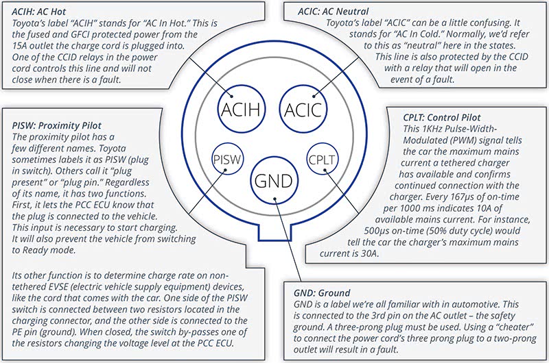
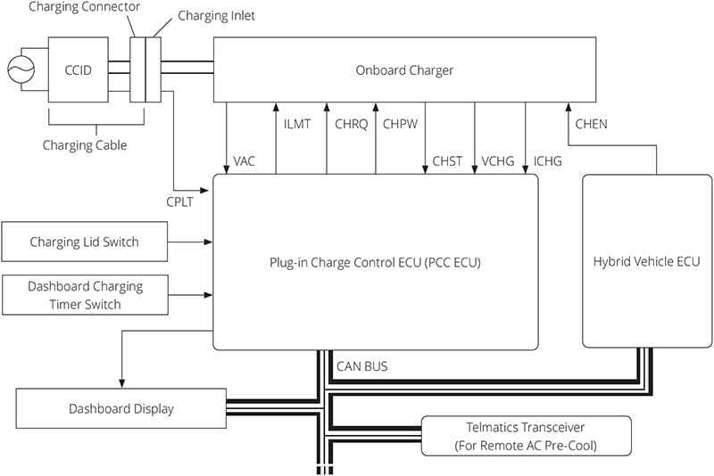
CPLT – The Control Pilot signal goes from the CCID box on the charging cable to the PCC ECU. It informs the PCC ECU about the output capabilities of the charging cable or charging station, as well as confirming that the cable is connected and the ground is good.
VAC – The input voltage AC signal comes from a voltage sensor built into the onboard charger. The VAC sensor has a linear DC voltage output, ranging from 2V—9V. It can report -500VAC to +500VAC.
ILMT – This is an abbreviation for “current limit.†This is somewhat like the control pilot signal. The CPLT communicates the charging station’s current capabilities. The ILMT signals the onboard charger’s current limit. For the Gen3 Prius PHV it should be a
10 Hz signal.
CHRQ – The PCC ECU sends the Charge Request signal to the onboard charger. This is a high/low signal. Less than 1V is a “don’t charge†signal. About 8V is a “charge†signal.
CHPW – The PCC ECU sends a 10 Hz PWM Charge Request Output signal to the onboard charger. This signal has a varying on-time based on desired output.
CHST – The onboard charger sends the Charge Status signal to the PCC ECU. When in standby mode, the signal is 25ms B+ every 100 ms. When in ready mode, the output is 50% on-time. If the charger detects a fault, the duty cycle is 78%. A fault condition can be caused by overheating, bad AC input, or a charger fault.
VCHG – A voltage sensor located in the onboard charger sends an analog voltage to the PCC ECU. Its normal range is from 1.72V to 6.0V.
ICHG – A sensor in the onboard charger reports current flow to the PCC ECU with an analog voltage signal ranging from 2V—7V. When in standby the sensor voltage is low; when charging, its voltage is higher.
CHEN – Charge Enable is a high/low signal from the Hybrid ECU to the onboard charger. With the key in the ON position, it should be less than 1V.
Diagnosis
We’ve covered how the system works. Now let’s talk about strategy for diagnosing problems. Since the power cord could be the problem, have your customer bring it in whenever possible.
As with all customer complaints, a good interview helps narrow down the possibilities:
- What actions do they take and what do they notice?
- Where does the problem occur? At home? At charging stations?
- Does it occur all the time?
- Does the car start charging normally but fail to complete?
Self-Diagnostic Capabilities
If you’ve worked as a technician, you know that sometimes the write up isn’t very good. You may not get a lot of details, or even a good description of the problem. You’re in luck though! Toyota includes a lot of great built-in diagnostic capabilities that make diagnosis of onboard charging easy. Here are some great tools:
- Codes and sub-codes with excellent descriptions of fault criteria in service information
- Detailed freeze frame data so you can see what the PCC ECU saw when it set the code
- “Charge cancel history,†which will tell you why the last several charge cycles stopped
- A catalog of oscilloscope waveforms, so you won’t need to guess if your signal is good
What Faults Can You Expect?
In electronics repair, power supply faults are among the most common. The onboard charger is in essence a power supply, just like what you might use to charge your laptop.
There are a couple things that make an onboard charger superior to a typical power supply. First, it’s much more robust than the power supplies found in consumer electronics. The other big difference is its self-diagnostic capabilities, as mentioned above.
Faults cans be categorized as follows:
- 12V supply faults. Voltage too low, too high, no voltage, etc.
- Internal ECU malfunctions
- Relay malfunctions. Sticking open, closed, failure to operate, etc.
- Voltage or current sensor outputs not as expected for the given condition
- Issues with the alphabet soup of communication signals we covered earlier
How to Start Diagnosis
With all the self-diagnostic capabilities included, it makes sense to start with a Health Check. Be sure to check the “Save all data†box and then save the file after the Health Check completes. You may need data later after you’ve done more research, and part of the diagnostic process may include clearing codes. You can’t get it back if you don’t save it.
If you have codes and freeze frame data, do some research on TIS and make a plan. Read the relevant section carefully so that you fully understand what the code means and what could have caused it to set. If there are no codes, be sure to check and note the “charge cancel†history, since the answer to your customer complaint may be there.
Often diagnostic procedures start with clearing the codes, verifying that the battery SOC is 70% or less, and then charging the battery. Well, you may not have a plug-in hybrid at home, and may not be familiar with the charging procedure. That’s OK.
It’s possible to be a great technician without knowing how every system functions. However, you need to do some research. The owner’s manual is usually a great place to start with an unfamiliar system. After all, you can’t fix it if you don’t know how it’s supposed to work. Use the reference tab on TIS to search for the manual, then use the PDF search feature to find the information you need.
Here’s a Cliff’s Notes version of some end-user-level information:
- The outlet used for charging should be on a dedicated 15A GFCI (Ground Fault Circuit Interrupter). The charger can pull 12A continuously, so other devices on the same circuit may blow the circuit breaker. Also, spikes caused by another high load device on the same circuit shutting off may damage the onboard charger.
- The CCID (Charge Circuit Interrupt Device) found in the cord’s box checks for ground faults in the car. It’s very similar to a GFCI, but it works with DC current and a GFCI only works with AC current.
- There is a test feature built into the CCID. Press the “Test†button to verify the CCID is working properly. The error warning should illuminate. The vehicle will not charge when the error light is illuminated. Press the reset button to clear the fault and enable charging.
- The charge cord should be plugged into the outlet before plugging it into the car, and more importantly, unplugged from the car before unplugging from the outlet.
- There is a charging indicator next to the charging port on the car. If this doesn’t light, the car will not charge.
- There is a charging timer. The car will not start charging immediately if the timer is blocking it. The timer can be used to fully charge the battery just before use (to increase battery life), or to take advantage of time of use discounts from utility companies.
Now you should know how to charge the car. One thing you won’t be able to duplicate is the owner’s home electrical set up, but you can communicate with the customer if that seems like a possible issue.
Recap So Far
- A car arrives with a charging complaint
- Perform a Health Check and save all the data
- Note any codes and Charge Cancel History data
- Research the data on TIS
- Clear codes and then charge the vehicle to determine if the fault is still present (usually).
Chasing a Repeatable Fault
There are a couple of ways to go about additional testing if there is a repeatable fault. Looking at live data is often a good place to start. Toyota usually includes a list of relevant PIDs on their code information pages. You can set up a recording and automatically add a flag when the code sets. Sometimes this is all that’s needed for a conclusive diagnosis.
Another method which may be necessary depending on the trouble code is verifying the alphabet soup of signals we talked about earlier using a voltmeter or oscilloscope. Here’s a short case study where we do a little testing with an oscilloscope.
Case Study
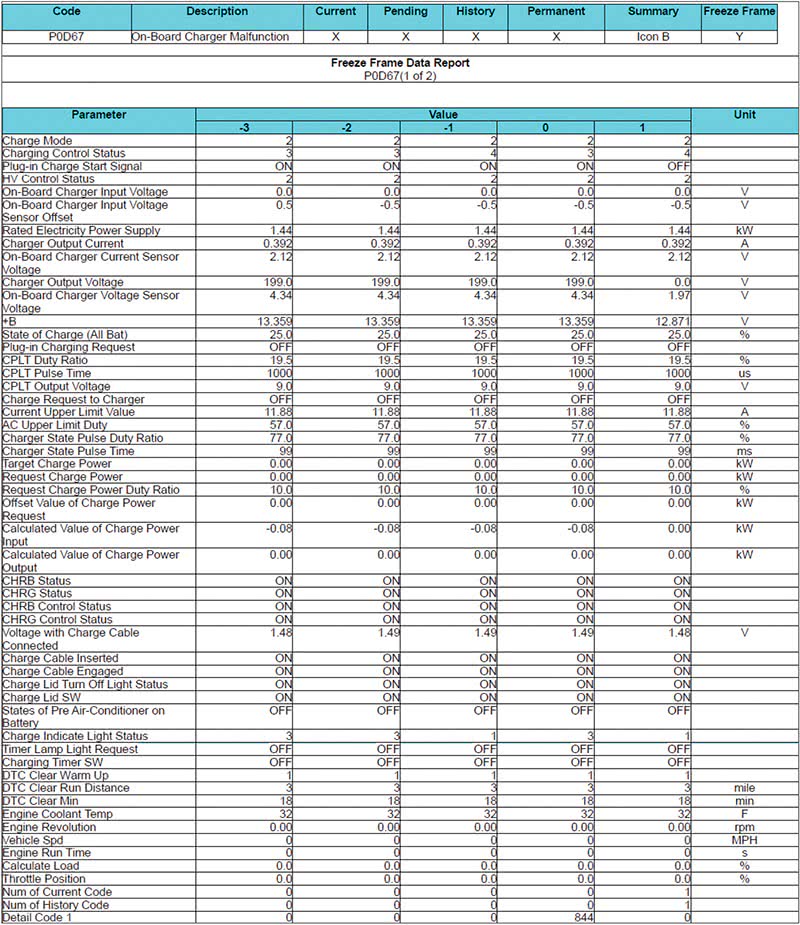
A 2015 Prius PHV came in with a P0D67-844 (onboard charger malfunction). This code sets when the charger’s internal self-diagnostic function finds a problem and it reports a problem to the PCC ECU via the Charge Status (CHST).
The car would always charge for a while but would stop before the charge was complete. This meant we had to be patient while waiting for the fault.
The diagnostic procedure for P0D67-844 is simple:
- If P0D67-844 is the only code, clear it and then charge the vehicle.
- If the code resets, check the “Charger State Pulse Duty Ratio†PID in live data and compare it to the actual duty cycle on the CHST terminal of the PCC ECU.
- If the duty cycle in the data and on the oscilloscope are the same, then the charger has an internal fault and needs to be replaced.
The only complication was waiting for the fault to occur. The Charge Status signal has three states: Standby (24% duty), Ready (51% duty), and Fault (78% duty). While the trouble tree only requires verifying that the duty cycle is the same in data and at the PCC ECU, ideally we’d see that when the Charger State Pulse went to 78%, the actual CHST signal also went to 78%. This was the case, so it looked like the charger was bad.
There is a potential “gotcha†here, covered in one of the very useful “hints†Toyota prints in green text.
If AC input voltage is dirty, meaning that it’s fluctuating in amplitude or frequency excessively, it may cause a P0D67-844. Hopefully, your shop has nice clean power, but you never know what your customer’s situation is. So, if a customer comes in several times with the same code but you can’t ever duplicate it, you may want to suggest they hire an electrician to check the quality of power at home.
In this case, a new charger was installed, and the issue was corrected.
0 Comments