
This focused tour of the Wiring and Function Diagrams, and Function Descriptions found in STAR Wiring and WIS will help you use this resource more effectively.
This focused tour of the Wiring and Function Diagrams, and Function Descriptions found in STAR Wiring and WIS will help you use this resource more effectively.
Unless you’ve been hiding under a rock, or you never see electrical problems in your shop (ha!), you’re already familiar with the electrical wiring diagrams found on STAR TekInfo and in WIS. What might still be a mystery are those Function Diagrams found in the same place, which are just as important to a solid electrical diagnosis as the wiring diagrams. Today, we’ll show you how these, along with the Function Description documents in WIS (the so-called GF documents) can help you perform a focused and professional electrical diagnosis.
Let’s start by taking a quick look at wiring diagrams. As examples we’ll use the ones found in STAR TekInfo, but the diagrams in WIS are nearly identical, the main difference being the way we can navigate inside these diagrams: In STAR TekInfo, we can use the mouse to drag the diagram to what we want to see, while in WIS we have to use the scroll bars at the edge of the window.
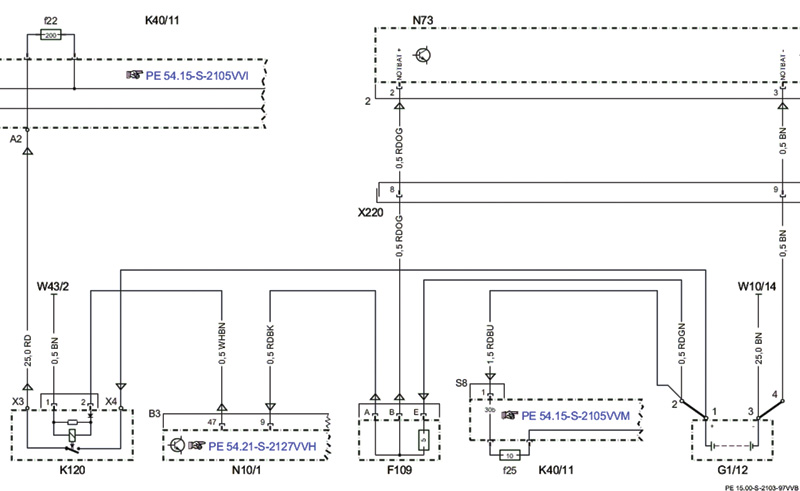
A wiring diagram is a two-dimensional representation of the physical wiring. We see the components and the wires that connect them, along with information about those wires and connections. For example, we might see a wire labeled as 0.75 GNBU, which means it has a cross-section of 0.75 mm2 (about 18 AWG) and has green insulation with a blue marking stripe. Note that this doesn’t mean it is 0.75 mm in diameter – in fact, the copper wire is just over one mm in diameter – it is the cross sectional area of the wire.
If we look closely at the connections to a component (including a wiring connector such as X220), we can see that one side of the connection is shown as a pin (usually on the component side) and the other side is shown as a socket. This tells you whether the electrical contact is male or female, helpful when you’re not sure which side of a connector you’re looking at. Of course, you can also see the component designation for each component (such as N10/1), along with the connector number (B3 on N10/1) and pin number (Pin 47 on N10/1 for the control signal to K120) for each individual wire connection.
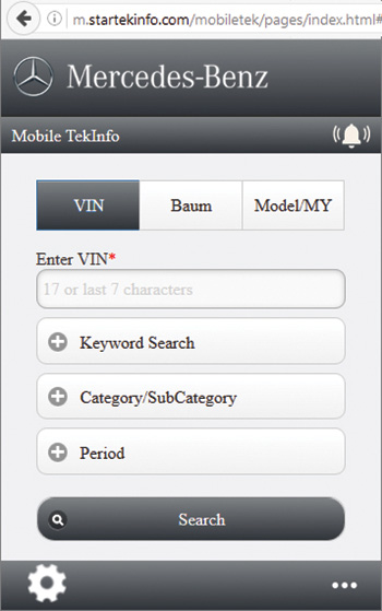
These symbols and features should be familiar, but some newer features in WIS and STAR Wiring are worth mentioning. In WIS, if you have a computer mouse with a wheel, you can use the wheel to scroll up and down in a document, zoom in or out by moving the wheel while holding the <Ctrl> key, or scroll horizontally by moving the wheel while holding the <Shift> key. This is especially handy in wiring diagrams. Also in WIS, if you’re not sure which Service Group contains the wiring diagram for a particular system, you can now search by Option (SA) Code. So if you need the diagram for PARKTRONIC (Code 220), you can search by SA Code (one of the options in “additional†Search Mode).
In STAR Wiring, you’ll find Signal Flow arrows. These don’t show the direction that current goes, but the direction that the signal goes. In other words, whether it is an input or an output (or both!). Additionally, you can now find the General Function documents (we’ll get to those in just a moment) on the System Information tab. These same documents can be found in WIS as document type “GF.â€
Back to our topic. We can clearly see that the wiring diagram is showing the physical wiring layout in the vehicle. It doesn’t show how long the wires are, or where they are located (although STAR Finder shows component locations), so it is not a perfect physical representation of the wiring, but it is close. If we wanted to check a wire, we should have little trouble finding each end for testing.
Until the early 1990s, wiring diagrams were all there was, and, really, all we needed. But then came networking, where a single wire could carry a multitude of information, with the technician having no way to see or measure what exactly was on that wire. Oh sure, we can measure the voltage to see if the CAN Bus is working normally, but without some kind of specialized test equipment, we could not, for example, tell what outside temperature value the A/C module was getting off the CAN Bus. Indeed, we couldn’t even know where the outside temperature signal was coming from.
After Mercedes-Benz introduced the CAN Bus for its products in the mid-1990s, technicians quickly identified the need to understand all the CAN messages that were being sent and received by the various control modules. Mercedes-Benz responded by introducing the so-called Function Diagrams. Instead of a pure physical layout, these diagrams show the signal flow between and among components, particularly the signals on the CAN Buses (and other networks). If we want to understand where a particular signal starts from, or which signals are being received off the CAN Bus, we can turn to the electrical Function Diagram.
Taking this one step further, if we want to understand what a system is doing with these signals – in other words, information on how a system operates – we can then use the Function Diagram together with the General Function (“GFâ€) document. In WIS, we need to search for the GF document as a separate document type, but in STAR Wiring there is a direct link to this function description.
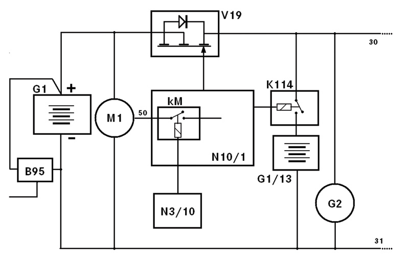
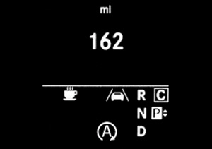
We already know about wiring diagrams, so let’s take a closer look at a Function Diagram. For this example, we’ll use the ECO Start function from the new Metris mid-size van, chassis type 447, and follow two signals from their origin to their destination.
| 1 |
Vehicle speed, signal |
|
CAN B |
Interior CAN |
| 2 | Instrument cluster, message | CAN C |
Drive train CAN | |
| 3 |
Fuel pump, specified pressure request |
| CAN E | Chassis CAN |
| 4 | Fuel pressure, status |
Code, EZ7 | Active Parking Assist | |
| 5 |
Starter circuit 50 relay, actuation |
|
Code, FZ5 |
ATA I, anti-theft alarm system |
| 6 |
Starter, actuation |
Code, G42 |
7G-TRONIC PLUS automatic transmission | |
| 7 |
Electronic Stability Program (ESP) control unit, status |
Code, HH4 |
THERMOTRONIC automatic air conditioning | |
| 8 |
Wheel speed, signal |
Code,HH9 |
TEMPMATIC semi-automatic air confditioning | |
| 9 |
Coolant temperature sensor, signal |
Code ZU7 |
Canada version | |
| 10 |
Engine start, request |
Code ZU8 |
USA version | |
| 11 |
Engine stop enable, status | G1 |
On-board electrical system battery | |
| 12 |
Crash, signal |
K40/10 |
Engine compartment fuse and relay module | |
| 13 |
Fuel temperature, signal |
K40/10kM |
Starter circuit 50 relay | |
| 14 |
Circuit 30, status |
K40/10kN |
Circuit 87M relay | |
| 15 |
ECO start/stop function button, status |
L6/1 |
Left front rpm sensor | |
| 16 |
Engine stop prohibited, request |
L6/2 |
Right front rpm sensor | |
| 17 |
Braking torque, signal |
L6/3 |
Left rear rpm sensor | |
| 18 |
Door rotary tumbler switch, status |
L6/4 |
Right rear rpm sensor | |
| 19 |
Accelerator pedal module, signal |
LIN B15 |
Battery sensor LIN | |
| 20 |
Engine speed, signal | M1 | Starter | |
| 21 |
Fuel pump with fill level sensor, actuation |
M3/6 |
Fuel pump with fill level sensor | |
| 22 |
Seat belt buckle restraint system switch, status |
N10/1 |
SAM control unit | |
| 23 |
Engine running, signal |
N118 |
Fuel system control unit (FSCU) | |
| 24 |
Automatic air conditioning (AAC) control and operating unit, status |
N15/11 |
Fully integrated transmission control (VGS) electric controller unit | |
| 25 |
Engine hood contact switch, status |
N2/ 18 |
Supplemental restraint system (SRS) control unit | |
| 26 |
Circuit 87, status |
N3/ 34 |
ME-SFI [ME] control unit | |
| 27 |
Gear range, request |
N30/ 4 |
Electronic Stability Program (ESP) control unit | |
| 28 |
Gear range, status |
N69/ 3 |
Left front door control unit | |
| A1/1 |
Instrument cluster (KI) control unit |
N72/ 1 |
Upper control panel (UCP [OBF]) control unit | |
| A8/1 |
Transmitter key |
N72/ 1s5 |
ECO start/stop function button | |
| B11/21 |
Coolant temperature sensor |
N73 |
Electronic ignition lock (EZS) control unit | |
| B37/4 |
Accelerator pedal module |
S62/ 41 |
Engine hood switch | |
| B4/21 |
Fuel tank pressure and temperature sensor |
S98 |
Air conditioning control and operating unit | |
| B70/2 |
Crankshaft Hall sensor |
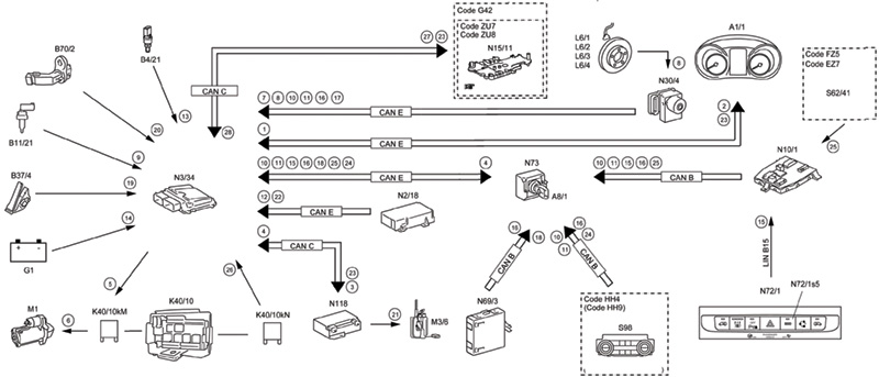
The first signal is the coolant temperature sensor, B11/21. Looking at the far left of the diagram, we see that B11/21 sends Signal #9 (Coolant temperature sensor, signal) on a directly-connected wire to the ME-SFI control unit (N3/34). We could also have seen this on the wiring diagram for N3/34, which would include physical details such as the wire size, color, and the specific connector and pin numbers, but would not tell us what the signal was. Of course, in this case the signal is obvious (the coolant temperature!), but the point is that the wiring diagram does not tell us that.
The second signal is from the engine hood switch, S62/41. If we look at the far right of the diagram, we see that S62/41 sends signal #25 (Engine hood contact switch, status) on a directly-connected wire to the SAM control unit (N10/1). If we look just to the left of N10/1, we see Signal #25 is sent over CAN B (the Interior CAN) to N73 (Electronic Ignition Switch). N73 then sends Signal #25 over CAN E to N3/34. If we look closely at the function diagram, we cannot find Signal #25 anywhere else, so we can be certain that no other control unit also receives Signal #25 for this particular vehicle function. From experience (and from the hint “Code FZ5†at S62/41), we can tell you that the hood switch signal is also used by the anti-theft alarm, but since ATA has nothing to do with ECO Start, that information is not shown on this diagram.

As a side note: Thin lines on a function diagram show a direct wired connection, while the wide “Bus†lines show signals carried over the CAN Bus. Dashed boxes tell us that the information only relates to vehicles with the option code or codes shown. And, as we saw, the numbers in circles are signals, and we can see where these signals go by following the numbers. These signals sometimes go to more than one place: Signal 23 (Engine running, signal) is sent by the ME-SFI control unit (N3/34) to both N118 (Fuel system, control unit) and N15/11 (Transmission control unit). Sometimes it takes a sharp eye to find all these, but the information is there for those who look.
Getting back to the basic idea for these: If we were trying to diagnose a problem with the ECO Start system, no matter how hard we looked at the wiring diagram for the ME-SFI control unit, we’d never figure out that the engine hood switch was being considered in the operation of this system. It would be just as hard to figure out exactly how the engine control unit was even getting that information. But a quick look at the function diagram, and Viola!, the mystery is solved in plain sight.
So now we can see just how the signals needed by the ECO Start system get around, and we have an almost fighting chance to understand how the system works: If we start with Signal #1 and work our way down the list, we (almost) have a bunch of clues as to what the system is looking at to decide if the engine can be shut down or not. For example, we can see that the A/C system (S98) has something to do with it, as does the left front door control unit (N69/3) and the SRS control unit (N2/18). But what, exactly, are these signals used for in ECO Start?
From our knowledge of professional diagnosis, we know that in order to diagnose all but the simplest of problems, we need two things: one is an accurate idea of the symptoms, and the other a thorough understanding of the system and how it is supposed to operate — exactly how it does what it is supposed to do (its Function). We get the symptoms from customers (why would they be in your shop otherwise?) and from our own attempts to duplicate the complaint, while using our knowledge of how the system is supposed to operate (gleaned from the operator’s manual). But understanding how the system functions is a little more complicated. Even if training is available, who could possibly remember the tiny, intricate details of how each system functions in every car ever made since forever?
Even the best of the best can’t remember everything. But all you need to remember is how to find the General Function document in WIS or STAR Wiring, and you have all the details right there in writing. If you use this document, along with the function diagram and the wiring diagram, and spend a few minutes studying the system, you will have all the information you need to thoroughly understand its function in great detail.
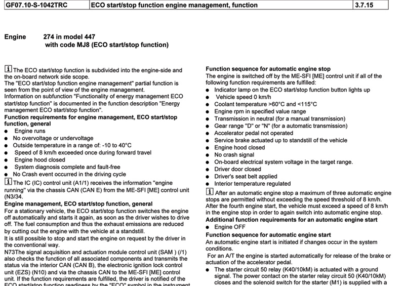
We’ve reprinted a portion of the General Function document GF07.10-S-1042TRC, which describes part of the ECO Start function as it applies to the M274 engine installed in USA-version Metris vans. Here, we can see that the engine is switched off by the ME-SFI control unit if all of the listed function requirements are met. One of these requirements is that the coolant temperature is between 60 and 115 degrees Celsius, and another is that the hood is closed. Looking closer, we can also see that the interior temperature must be in regulating phase – the A/C or heat has the temperature at or near where it’s supposed to be – and that there must not be any Crash Signal received from the SRS control unit.
As you’ll remember, we saw all four of those signals – engine coolant, hood switch, A/C unit, and SRS unit – on the function diagram, but didn’t have any real information on what, exactly, they had to do with ECO Start. Now, using the GF document, together with the function diagram, we know what they do, and can consider what might happen (what symptoms we might see) if these were not working properly.
Which is the whole point: We want to fix the customer’s car (or van) as quickly as possible, and we want to be certain that we really fixed the problem. This makes for happy customers, and we all know that happy customers come back when they need us again. So if we make the investment in Mercedes-Benz information systems, we know we’re able to get the detailed information we need to really understand the system’s function, make a professional diagnosis, and perform a permanent repair. For sure, we can get wiring diagrams from other sources, but Function Diagrams and General Function documents, especially from The Source, can prove more valuable than we realize.
Mercedes-Benz USA offers this information, which is exactly the same as what Authorized Mercedes-Benz Dealers get, to independent workshops like yours because the company recognizes that your customers are also its customers. No matter who services the vehicles, every Mercedes-Benz customer deserves only the very best, and, with the right tools, parts and information, you can deliver on that promise.


0 Comments