
Introduced in 2011 with the CLS (218) model, virtually every new Mercedes-Benz model that’s appeared since then has this innovative system. We’ll explain how it works and offer some tips for when something’s not quite right.
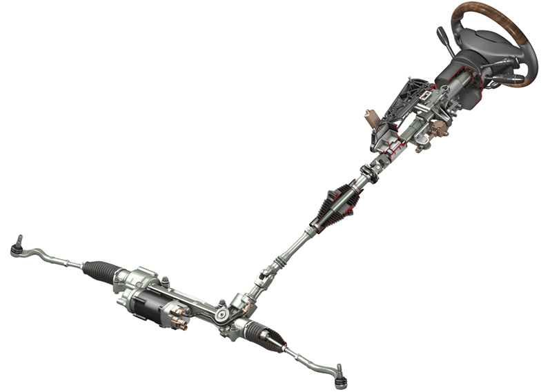 You’ve probably seen a few cars with electric power steering pass through your shop by now. Introduced in 2011 with the CLS (218) model, virtually every new Mercedes-Benz model that’s appeared since then has this innovative system. In this article, we’ll explain how it works and offer some tips for when something’s not quite right.
Why go electric?
Daimler engineers needed a way to get rid of the power steering pump. It steals energy from the engine, hurting fuel economy, and takes up precious room at the front of the engine. It wouldn’t hurt to get rid of power steering fluid, along with the weight, plumbing, and potential leaks involved. Also, if a road hazard, accident, or fire should prevent the system from providing assistance, you’d be able to steer the vehicle without the heavy resistance of hydraulics. So, the electric power steering system was developed.
Although one of the main advantages is weight, power consumption is reduced while a few valuable new features become possible: When the engine is stopped under ECO Start/Stop operation, the power steering boost remains available. With the new Assist Systems from Mercedes-Benz, sub-systems like Steer Assist (which helps the driver make the right steering choices during critical maneuvers) and DISTRONIC PLUS (a portion of which can actually steer the car for a brief while) become possible. If the car encounters an uneven road surface (say, due to highway construction), the electric power steering system can apply a small steering force to help counteract any negative influences, as well as to counteract similar forces when braking hard. All this means the car is more predictable, easier, and safer to drive.
You also get an enhanced steering feel, which can be carefully controlled by the design engineers instead of being left to chance by the vagaries of an electro-hydraulic design. This really comes in handy in the AMG models, where the steering feel can be changed in software instead of hardware. Plus, the steering wheel return-to-center is power-assisted, no longer dependent upon the front end’s caster to deliver this important necessity. Not to mention the Parking Assist system, which parks the car automatically, both parallel and perpendicular. These are all features Mercedes-Benz customers want and deserve.
How it works
 and is sensed by the torque sensor (3). The worm gear (5), which is part of the steering rack, is then driven side-to-side via an electric motor (not shown) managed by a control unit according to the torque sensor input. If the electrical system fails, the helical gear (1) drives the worm gear (5) and thus the steering rack directly. Image Credit: ZF Lenksysteme")
The driver’s steering force enters through the steering column drive pinion (6) and is sensed by the torque sensor (3). The worm gear (5), which is part of the steering rack, is then driven side-to-side via an electric motor (not shown) managed by a control unit according to the torque sensor input. If the electrical system fails, the helical gear (1) drives the worm gear (5) and thus the steering rack directly. Image Credit: ZF Lenksysteme
The entire steering rack is self-contained, composed of the mechanical parts, a powerful electric motor, and the control unit. An Input Torque Sensor detects the steering shaft input torque from the driver, and the control unit calculates the electric power needed to drive the electric motor to assist the steering rack’s side-to-side movement.
The system is in operation when Circuit 15 (ignition) is on, the engine speed is greater than 400 rpm, and vehicle speed is above zero. The torque sensor, along with the steering wheel’s steering angle sensor (which also delivers steering speed) is used to determine the steering needs.
The torque sensor is found on the input shaft, well-protected against the steering housing. The input shaft passes through the torque sensor and ends inside the housing, with a pinion gear connected to the steering rack, providing a backup way of steering the vehicle, albeit without power assist, if there is some kind of system or electrical fault.
 is driven by the electric motor shaft (3) via a toothed belt (2) and pulley (4). The recirculating ball nut (5) moves the rack side to side with very low friction as the ball bearings (7) move along the screw thread cut into the rack. The bearings are recirculated through channel (6) continuously. The nut only rotates, it does not move side-to-side. Image Credit: ZF Lenksysteme")
The steering rack (1) is driven by the electric motor shaft (3) via a toothed belt (2) and pulley (4). The recirculating ball nut (5) moves the rack side to side with very low friction as the ball bearings (7) move along the screw thread cut into the rack. The bearings are recirculated through channel (6) continuously. The nut only rotates, it does not move side-to-side. Image Credit: ZF Lenksysteme
To steer the car, the control unit powers the electric motor, which transmits its rotation using a toothed belt to a recirculating ball nut. As the nut turns, the ball bearings inside drive the screw thread cut into the rack, moving it side to side with very low friction. The friction is so low, in fact, that you can push the rack side-to-side by hand if necessary (back-driving the motor) as long as Circuit 15 is off. This ability to move is necessary for the backup steering function to operate.
There’s also a data network connection to the steering control unit. Not only does this allow for steering requests from other vehicle systems (ESP, Parking Assist, and DISTRONIC, for example), it allows for diagnostics, using your XENTRY machine. Note that generic aftermarket diagnosis scan tools do not usually have capabilities beyond drivetrain systems.
If the engine is off, or the vehicle stopped, there is no power assist. In vehicles equipped with ECO Start/Stop, the power steering assistance remains active (but at a reduced level) even if the vehicle is not moving, provided the engine was stopped by the ECO Start/Stop function.
Spare Parts
 can only be replaced as an assembly, but it is available as a remanufactured part for a considerable cost savings. Note that the tie rod ends (80, inner and 60, outer) are also available as spare parts, along with the rubber boot (20).")
The electric steering rack (10) can only be replaced as an assembly, but it is available as a remanufactured part for a considerable cost savings. Note that the tie rod ends (80, inner and 60, outer) are also available as spare parts, along with the rubber boot (20).
If we take a look at the Electronic Parts Catalog, we see that none of the internal components of the steering gear are available. It is only replaceable as a complete unit, but it is offered as both brand-new and remanufactured. The rebuilt units can save your customer about $1,000 as compared to the new, and, as with all Genuine Mercedes-Benz Parts, they both carry the same one-year unlimited mileage replacement warranty.
When the system was first introduced, some technicians expressed their concerns about the toothed belt, figuring it was going to wear and fail, resulting in high costs for what is essentially a low-dollar part. Over the years, these fears were proved to be unfounded. This kind of belt has been used by other industries for many years without any problems.
Maintenance
, which is found at the lowest point of the main steering gear housing. If you find one that has opened it must be replaced along with whatever’s letting the water in. Refer to WIS for details.")
Early versions of the electric steering systems are equipped with a water drain valve. In the inset image at the bottom, on the left is a new valve, on the right is one that has opened due to water within the electric steering case. Always look for the valve (4), which is found at the lowest point of the main steering gear housing. If you find one that has opened it must be replaced along with whatever’s letting the water in. Refer to WIS for details.
Unlike the power steering systems we’ve known since forever, there are no hydraulic components. The steering power boost is delivered by an electric motor instead. And, also unlike previous systems, electric power steering is maintenance-free. Indeed, the only replaceable parts in the system are the inner tie rod ends and their boots.
That doesn’t mean nothing will ever need attention, however. Although in practice the system has shown itself to be extremely reliable, as with any mechanical system things may wear and need replacement.
In early versions of the electric power steering system, the case was equipped with an automatic water drain valve. The valve has a water-soluble “pill,†which dissolves when in contact with water, allowing spring pressure to open the valve and release any water trapped within the housing.
If you get a car with electric power steering in your shop, always check for a water drain valve. If one is present, inspect it. If it has opened, it must be replaced, ideally along with a careful inspection to identify the source of the water entry — most often the rubber boots surrounding each tie rod.
If you do find an open water drain valve, be sure to check the toothed rack for corrosion and, depending on the severity, consider replacing the steering rack. Check the Workshop Information System (WIS) document AR46.20-P-0005EW for the detailed inspection and replacement procedure and tightening torque for the drain valve. The valve carries part number A218 461 00 02 and is readily available.
If you don’t find the water valve on the steering rack housing, don’t panic: Later system versions eliminated this drain valve around 2014, since water sealing was found to be a non-issue. In its place, you’ll find a flattish spot on the housing, marking the low spot when it’s installed.
Diagnosis
If the electronic control unit detects a fault, it sends a message to the driver via the Instrument Cluster: “Power Steering Defective! Service Required!â€Â Using XENTRY, you can view the basics, including fault codes and actual values, but the bottom line is that there are no replaceable parts inside, so unless the fault is related to an external influence – CAN Bus faults, power and ground, or the like – there’s little else to do.
Repair work
 has failed, it may allow water and dirt to enter the steering housing, leading to early failure. For the inner joint, hold the steering rack shaft (14) while unscrewing the holding nut.")
Both the inner and outer tie rod ends are replaceable, as are the inner flexible boots. If the boot (11) has failed, it may allow water and dirt to enter the steering housing, leading to early failure. For the inner joint, hold the steering rack shaft (14) while unscrewing the holding nut.
As these vehicles age, you may start to see worn inner tie rod ends. These are found within the rubber bellows boots at each end of the steering rack. If a bellows is torn or damaged, not only must it be replaced, but the dust and dirt has probably caused some damage to the inner tie rod end.
To replace it, remove the boot using your click-clip pliers, counter-hold the shaft while you loosen and unscrew the nut holding the tie rod in place. Replace the parts as needed, then tighten the nut to the specified torque to ensure proper operation. You can find the specs in WIS. Reinstall the boot and clamps and perform a complete wheel alignment.
Of course, replacing the outer tie rod ends is much simpler, since the entire part is exposed. Do check the work instructions in WIS, however, since there is a special tool used to separate the tie rod end cone from the steering knuckle that will save you time and grief.
If you have to replace the entire steering rack, be sure to follow the WIS work instructions carefully. Some of the Mercedes-Benz special tools, particularly the pullers for the tie rod ends and steering knuckle bolts, make the job so much easier than using a pickle fork or hammer that buying them for even a single job is well worth it for the time savings, doubly so if you accidentally damage any of these parts.
There are several “gotchas†in the job, such as replacing all the single-use fasteners and maintaining steering shaft alignment, and the special two-stage bolt tightening sequence that is critical to follow for the bolts in this safety-related system. Several of the steps in the work instruction vary depending on which model you’re working on. There is simply no substitute for having the work instructions right there to guide you.
Noises
The power steering rack itself is rarely the cause of any strange noises, but you can hear a slight motor hum and whine under the right conditions. It is unlikely your customer will complain of this, however. Instead, you will be faced with the other usual suspects: ball joints, tie rods, and so on.
The first step when trying to diagnose any noise complaint is to duplicate the problem. After all, until you can make it happen, how can you be sure you’ve made it go away? StarTuned has covered the diagnostic process in previous issues, so we won’t repeat it here, but duplicating the problem is a point worth repeating.
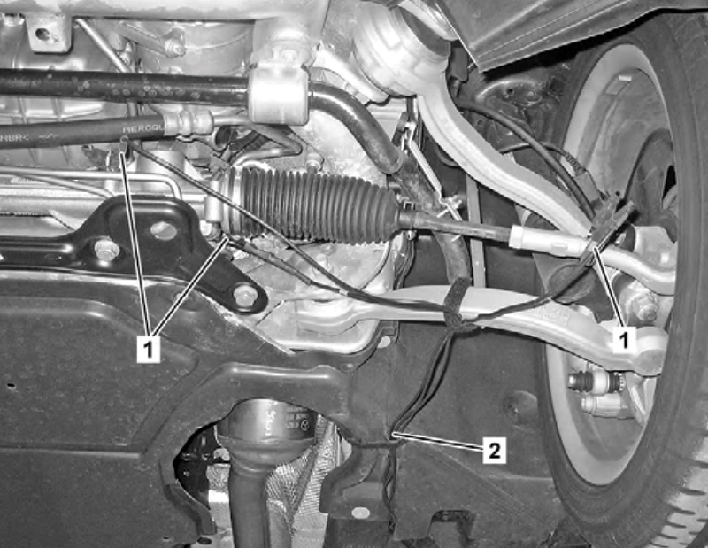
When trying to diagnose noises from the steering and suspension, clamp-on microphones really help to pinpoint the source. Here we see three clamp-on microphones (1) and the associated wiring (2), carefully routed to avoid affecting any chassis or steering movements and preventing any damage to the wiring or microphones. Listening and driving is a two-person job.
Mercedes-Benz recommends a noise diagnosis system, similar to the well-known Chassis Ears, from Gayle Technologies, available on the open market for about $550. This system is also recommended by a few other manufacturers, and its value extends beyond chassis noises. To use it, you clip, clamp, tape, or otherwise fasten microphones to the chassis near the suspected source of the noise, then have a colleague drive while you listen. Just make sure you don’t restrict the movement of the chassis or steering, which could break your microphone or even cause an accident. Same with driving with the headphones on: You’re risking too much, so just don’t.
Â


Would like to see the wiring diagram and electrical connector points since those are the only maintenance check points– ie a an intermittent electrical problem not giving a fault code.
Hi John,
Our editor provided some information that may be useful.
“I’m not seeing connectors as a maintenance item, but in vehicles equipped with EPS, the associated wiring diagrams will show the connections. I can’t say they show the connectors themselves though, just what’s in WIS.
Here is the wiring diagram from STAR Wiring for a CLS (Model 218). A91m1 (top right) is the EPS Motor, physically attached to the control unit N68: https://bit.ly/cls-218-wire.
In the ‘location’ photo, at the top right of N68 (black lump) you can just see the main power input connector, it has a white ‘stopper’ in it. You can also see how the ‘big’ power to the motor is a completely internal connection: https://bit.ly/n68-connector.”
We hope that helps.