Air/fuel mixture data from your scan tool can go a long way towards narrowing the diagnostic path when you are faced with a no-code driveability or engine performance problem.
With the introduction of variable valve timing, Nissan was among the first to incorporate a mixture ratio feedback system that maintains the air/fuel mixture as close as possible to the ideal stoichiometric ratio to provide complete combustion of the fuel in the cylinder, under normal conditions. Complete combustion helps achieve not only the best engine performance, but also good fuel economy.
Mixture control also allows rapid cycling of the air/fuel mixture from slightly rich to slightly lean and back. This helps the three-way catalyst (exhaust manifold) to better reduce emissions of harmful carbon monoxide (CO), hydrocarbons (HC) and nitrogen oxides (NOx).
A slightly lean mixture ensures that enough oxygen enters the converter to help the oxidation stage of the catalyst burn any unburned HC and CO.
But too much oxygen in the converter makes it easier for nitrogen atoms that have been ripped from NOx molecules by the catalyst to find and re-bond with the oxygen into new NOx before exiting the exhaust. The mixture ratio feedback system prevents this by temporarily increasing the amount of fuel in the exhaust through adjustment of the air/fuel mixture. This creates the rapid cycling of the A/F and O2 sensor signals from lean to rich and back when the system is functioning properly.
Closed Loop Operation
Nissan’s engine control module (ECM) monitors the signal from the oxygen sensor 1, located in the exhaust manifold, to see whether the engine is operating rich or lean. The ECM adjusts fuel injector pulse width accordingly.
The cycle then repeats. The oxygen sensor tells the ECM what amount of oxygen is entering the converter, the ECM tells the fuel injectors how much to increase or decrease fuel flow into the engine, and the ECM then monitors the oxygen sensor 1 to see if it achieved the commanded air/fuel mixture. This cycle is called closed loop operation.
The ECM also uses the signal from a heated oxygen sensor (HO2S2) located downstream of the three way catalytic converter to check the function of the oxygen sensor 1. Under normal conditions the HO2S2 is not used for engine control. If the switching characteristics of the oxygen sensor 1 deteriorate, the air/fuel ratio is still controlled to stoichiometric by the ECM, using the signal from the HO2S2.
The oxygen sensor 1 does not provide accurate readings at temperatures below approximately 800 degrees C (1,472 degrees F). Similarly, an HO2S2 needs to reach approximately 398 degrees C (750 degrees F) before it can give accurate voltage readings. Closed loop operation cannot begin until the oxygen sensor 1 and HO2S2 reach the required operating temperatures aided by built-in heater elements to accelerate their warm up on cold start engine operation.
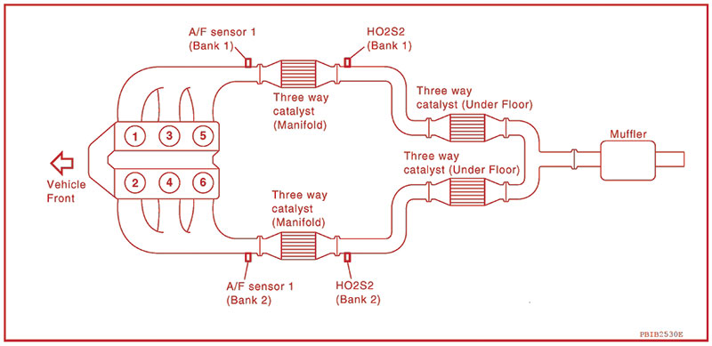
The 2011 Pathfinder 4.0L V-6 engine control system includes heated oxygen sensors, three way catalytic converters, and other sensors (not shown) on both engine banks.
Open Loop Operation
The ECM controls operation of the HO2S2 heater element in conjunction with engine speed, the amount of intake air (engine load) and engine coolant temperature. The ECM commands the HO2S2 heater element ON when engine speed is below 3,600 rpm after the engine has begun warming up, and has been idling for at least one minute under no load. Above 3,600 rpm, the ECM shuts the HO2S2 heater element OFF.
Until the engine has warmed up, and the oxygen sensor 1 and HO2S2 have reached their required operating temperatures, A/F mixture control is in open loop operation. The ECM regulates fuel injector pulse width so that the air/fuel mixture matches a stored base value that is in the ECM prior to any learned on-board corrections. Nissan calls this “base fuel schedule,†and labels it “B/FUEL SCHDL†in its CONSULT series scan tools.
The base fuel schedule maintains a stabilized fuel combustion while the engine is in open loop control. Until it switches to closed loop operation, the ECM does not alter the base air/fuel mixture command.
Open loop operation occurs when the ECM detects any of the following conditions:
- Deceleration and acceleration
- High-load, high-speed operation
- Malfunction of the oxygen sensor 1 or its circuit, including insufficient activation of the oxygen sensor 1 at low engine coolant temperature
- High engine coolant temperature
- During engine start-up, warm-up, or immediately after shifting from N to D
Fuel Trim
Once the engine has warmed up and is in closed loop operation, engine conditions are monitored and continuously modified by the ECM to provide the best combination of engine performance, fuel economy, and emissions control. Fuel trim refers to the fuel injector pulse width adjustments made to the base fuel schedule by the ECM. It includes short-term and long-term adjustments.
Short-term fuel trim (STFT) is an immediate, rapid adjustment to maintain the mixture ratio at its stoichiometric value. The voltage signal from the oxygen sensor 1 indicates whether the mixture is rich or lean compared to that ideal value. The ECM reduces injector pulse width if the mixture is rich, and increases fuel volume if it is lean.
Long-term fuel trim (LTFT) is an adjustment that occurs when the ECM sees frequent, increased deviations in the STFT from the stoichiometric air/fuel ratio. These deviations may occur more over time as cylinders fail to seal as well as they once did, the engine evap system loses capacity, the fuel delivery system becomes less efficient, and other signs of normal wear begin to appear.
Within five to twenty seconds of noticing a consistent larger up or down deviation than before, the ECM calculates a new adjustment percentage to compensate for a significant portion of the changes. That new number is the LTFT.
By absorbing a large portion of the consistent deviation, LTFT leaves a much smaller adjustment task to the STFT factor. This allows STFT to make faster, more precise responses to rapid changes in engine operating conditions such as acceleration, intake air flow and other real-time load condition indicators.
High Fuel Trim? Ask Why.
Fuel trim numbers are displayed in OBD-II readouts as a percentage of fuel added to or subtracted from the base air/fuel ratio. A general guideline is to investigate further whenever the total of STFT and LTFT is greater than 10 percent. This is true whether the difference is higher (trending rich), or lower (lean).
For example, if STFT is +3 percent and LTFT is +5, the total of +8 percent may be acceptable. However, a 3 percent increase in STFT may look acceptable, until you see a +12 percent LTFT. The 12 percent LTFT increase (and +15 percent total) is covering for a problem.
The +15 percent total fuel trim may not be high enough that the ECM sets a trouble code. A problem affecting fuel trim could originate anywhere between the intake air filter and the exhaust manifold. On an overhead cam V-type engine where there are two each of timing, air/fuel mixture control, and sometimes even catalyst system and other components, you have a lot of diagnostic ground to cover.
Unbalanced Fuel Trim Narrows the Search
“A/F ALPHA†is Nissan’s term for the percentage of air/fuel ratio correction commanded by the ECM per engine cycle in closed loop operation. On some V-type engines, it can be looked up separately for each bank. In this example on a 2011 Pathfinder with a 4.0L V-6, you can use Nissan’s CONSULT series or your scan tool to get a quick indicator of whether fuel trims differ by engine bank.
First, warm the engine up to normal operating temperature, and check that the “FLUID TEMP SE†(A/T fluid temperature sensor signal) indicates more than 60 degrees C (140 degrees F). Make sure that the rear window defogger, air conditioner, and lighting switches are OFF, and the steering wheel is straight ahead.
Look up A/F ALPHA-B1 and A/F ALPHA-B2. The value should average between 95 and 105 (plus or minus 5 percent of the base fuel schedule) for each engine bank. If the deviation is outside of the specified 95 to 105 percent adjustment range, and either bank is significantly different from the other, focus your next investigative steps on the bank with the highest deviation from the base fuel schedule.
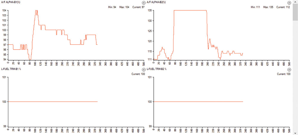
We unplugged a single fuel injector on bank 2 on a 2005 Pathfinder 4.0L V-6, causing A/F ALPHA B2 (short term fuel trim) to add fuel at a consistently higher rate (Minimum 111 vs. Minimum 94 for B1), and to add a significantly larger amount of fuel than bank 1 in the approximately 120 data points between the 80 and 200 mark.
Intake Valve Timing
Dual overhead camshaft (DOHC) designs advance or retard timing of the intake camshaft under different engine operating conditions to improve low or high speed torque. When lower engine speeds result in less intake air entering the engine, the intake valve should ideally close early, to prevent the rising piston from forcing some of the combustion chamber’s just-received air back up the intake port.
As speed increases and more intake air enters the engine, the intake valve should remain open longer, to allow more air into the combustion chamber. The minor timing overlap this creates between intake and exhaust valves is desirable at higher engine speeds. It allows the slight negative pressure created by gases being pushed out of the exhaust port to help draw more intake air into the combustion chamber, a process we know as “scavenging.â€
Too much valve overlap at lower speeds can be a problem. A high amount of exhaust gas forcing its way back into the intake manifold will make the vehicle feel as if it cannot make up its mind at what rpm level to operate. This hunting or inconsistent rpm also reduces cylinder compression.
Nissan’s intake management system uses computer-operated intake valve timing (IVT) control solenoids to precisely meter the valve opening and closing cycle. In response to ON/OFF pulse duty signals from the ECM, this IVT control solenoid valve, or cam phaser, changes the amount and direction of flow of oil through a hydraulic valve that mechanically alters cam timing. Longer pulse width advances intake timing, and shorter retards it.
If the IVT control solenoid valve’s oil passages become clogged, the valve could become stuck and cause drivability problems. Alternately, if an incorrect voltage signal is sent to the ECM from the IVT control solenoid valve, it could cause a mismatch between the actual phase control angle degree, and the degree expected by the ECM.
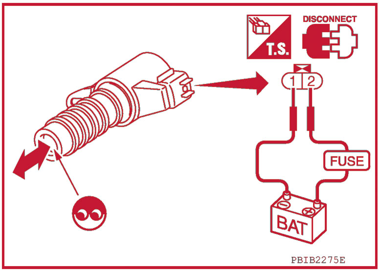
The plunger in the IVT Control Solenoid Valve should move out and back into the valve body when you apply battery voltage between terminals 1 and 2. If it does not, the valve’s oil passages may be clogged.
Intake Timing by Engine Bank
On our 2011 Pathfinder V-6, with the engine warmed up, shift lever in P or N, A/C OFF, and no engine load, we can check the INT/V TIM (B1) and INT/V TIM (B2) readings in CONSULT III or on a generic scan tool.
At idle, crankshaft advance should be -5 degrees to +5 degrees CA. At 2,000 rpm, you should see approximately 0 degrees to 30 degrees CA (Crankshaft Angle). If either bank shows a reading that is out of the specification range, it should set a P0011 (B1) or P0021 (B2) trouble code.
If no DTC is set, look for differences in the reported numbers between B1 and B2. Then look further for issues on whichever side of the engine appears more out of range of the specification.
IVT Control Solenoid Valve Circuit Function by Bank
You can check whether the IVT control solenoid valve circuit is functioning properly by looking up, under the same engine operating conditions, INT/V SOL (B1) and INT/V SOL (B2) on your scan tool. At idle, the reading should be between 0 to 2 percent. At 2,000 rpm, it should show between 0 to 50 percent.
If there is an open or short in the intake valve timing control solenoid valve circuit, it should set a P0075 (B1) or P0081 (B2) DTC. If no code is set, check resistance of the IVT solenoid valve on whichever side appears nearest to exceeding the specified value.
Checking the IVT control solenoid valve between terminals 1 and 2, resistance should be 7.0 – 7.7 Ω (ohms) at 20 degrees C (68 degrees F). Checking between terminal 1 and ground, you should see zero continuity. If one side or the other fails, replace the IVT control solenoid valve on that side.
If neither side fails, but you suspect the INT/V SOL reading, you can check to make sure the solenoid valve plunger is not stuck. Provide 12V DC between the IVT control solenoid valve terminals, and then interrupt it. The plunger should move out and back into the valve body as you apply and remove voltage. CAUTION: Never apply 12V DC continuously for 5 seconds or more. Doing so may damage the coil in the valve.
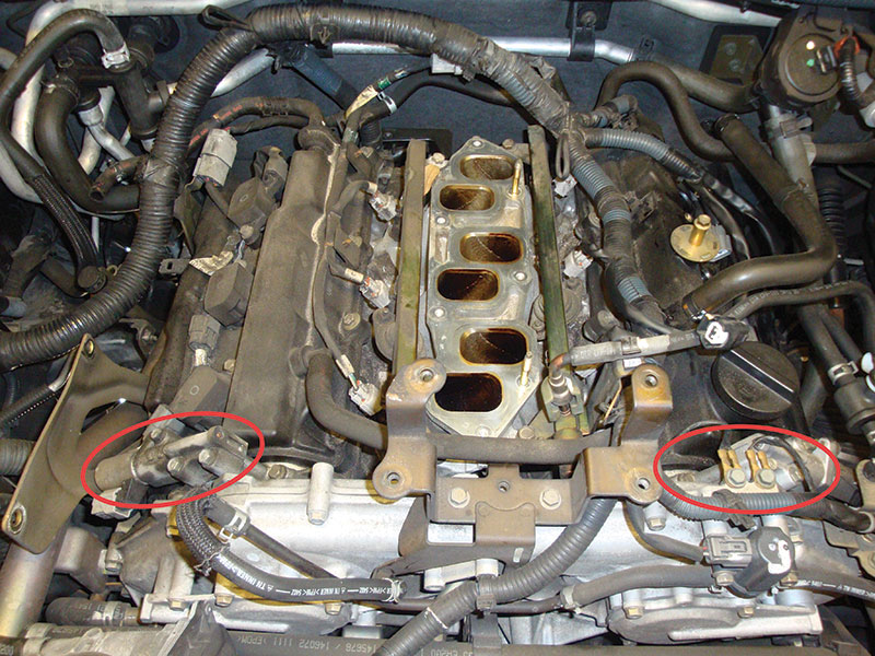
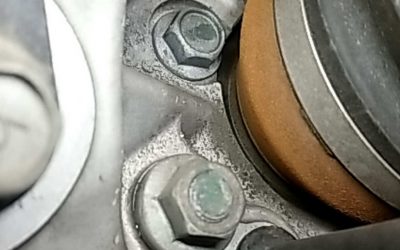
The intake valve timing (IVT) control solenoid valves are located on either side of the front of the engine block. The bank 1 IVT control solenoid valve is on the passenger side.
Oxygen Sensor Function by Bank
Heated oxygen sensors are located after the catalytic converter and generate a voltage that is close to 1 when the exhaust gas mixture is RICH, and nearer to 0 when it is LEAN. Our 2011 Pathfinder V-6 engine contains post-catalytic converter heated oxygen sensor locations on both engine banks. We can look up HO2S2 (B1) and HO2S2 (B2) using CONSULT III or a generic scan tool.
The ECM groups the errors it detects into three categories. The sensor does not reach the specified high voltage level when the exhaust mixture is RICH, does not fall to the expected low when the mixture is LEAN, or the switching cycle time is too slow.
The voltage signal should reach above 0.68 volts at least once during its switching cycle. If it does not, the circuit may be open or shorted, the sensor may be dying, there may be intake air leaks, or there may be a fuel delivery problem. Either way, the ECM should set a code P0137 (B1) or P0157 (B2).
If the HO2S2 readout is above 1.2V, or does not reach below 0.18V at least once during its switching cycle, either the sensor circuit is sending a false high reading, or there may be a problem in the fuel delivery system. The ECM should set a P0138 (B1) or P0158 (B2) DTC.
The ECM knows how long a post-catalytic converter heated oxygen sensor should take to switch from rich to lean and back. If the switching time is longer than specified, there may be an open or short in the circuit, the sensor could be failing, or there may be a problem in the fuel, EVAP, or intake air system. The ECM should set a P0139 (B1) or P0159 (B2) DTC.
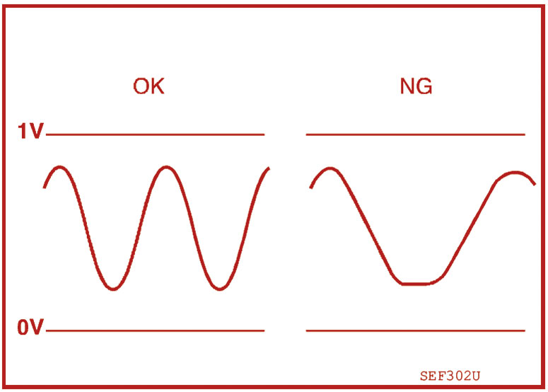
If it takes longer than specified for an 02 sensor to switch from RICH to LEAN and back, the ECM will set a trouble code.
Oxygen Sensor Function by Bank
An oxygen sensor outputs a continuous signal that varies with oxygen content in the engine exhaust. Because it indicates exactly how much oxygen is in the exhaust, oxygen sensor feedback allows the ECM to more precisely adjust the air/fuel ratio. Using CONSULT III Plus or a generic scan tool, we can look up oxygen sensor 1 data for both bank 1 and bank 2 on our 2011 Pathfinder V-6.
When the ECM adjusts STFT or LTFT, it expects the voltage reading from oxygen sensor 1 to quickly reflect a changed mixture. If it does not, the ECM thinks there is something wrong with the sensor or its wiring circuit, and sets a trouble code.
If the oxygen sensor 1 output is consistently showing 0V, the ECM considers it too low for the base fuel schedule, and sets a P0131 (B1) or P0151 (B2) DTC. If it consistently shows approximately 5V, the ECM thinks it is too high, and sets a P0132 (B1) or P0152 (B2) DTC.
If it consistently shows any other voltage amount despite the fact that STFT or LTFT is changing, the ECM sets a P0130 (B1) or P0150 (B2) DTC.
If the oxygen sensor 1 shows a switching cycle time that is slower than specified in Nissan’s algorithm, the ECM sets a P0133 (B1) or P0153 (B2) DTC.
Check Other Sensors by Bank
There are other sensor readouts that can easily be checked by bank 1 or bank 2 using CONSULT III Plus or a generic scan tool. These include:
- FUEL SYS-LEAN-B1 and FUEL SYS-RICH-B1 (for fuel injector function, both also available for B2)
- TW CATALYST SYS-B1 and TW CATALYST SYS-B2 (three way catalyst)
- KNOCK SEN/CIRC-B1 and KNOCK SEN/CIRC-B2
- CMP SEN/CIRC-B1 and CMP SEN/CIRC-B2 (camshaft)
- Codes for the built-in heaters for the oxygen sensors
- Misfire codes for each individual cylinder
Most of these sensors that have bank 1 and bank 2 locations on a V-type engine can be checked from the OBD-II port (diagnostic data link) under the dash. You won’t even have to pop the hood to get started narrowing your diagnostic path to one side of the engine or the other.

Repair of a simple exhaust gas leak before the three way catalyst (manifold) on either bank could clear up a few errant engine control sensor readouts.



0 Comments