
Sure, it’s a boon to performance, but the system is a possible trouble spot when a big number’s on the odometer. The mechanism itself, stretched chains and worn tensioners that sometimes don’t set DTCs, and zeroing in on the problems associated with troubleshooting these systems.
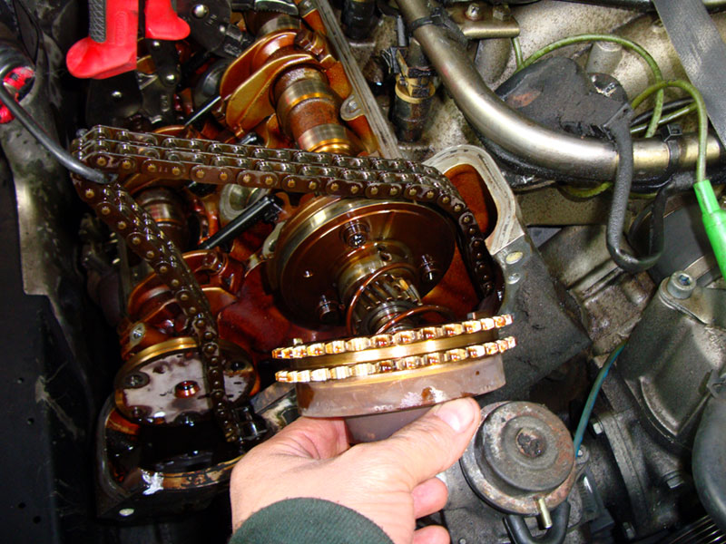
VVT sprocket
As engines evolved and running rpm became much higher than idle rpm, the need for a way to change the lift and duration of the valve timing became necessary to optimize performance and economy. It was in the 1920s that the first patents for variable-duration valve opening started appearing.
Valve timing in the internal combustion engine generally represents a compromise with regard to the requirements placed on torque, power output, and fuel economy. The need for a system to address this compromise became more evident in the late 20th century due to the demand for better fuel economy and the environmental concerns we began facing. Combining this with the thirst for power, car buyers made it necessary for this technology to be developed and to evolve into the sophisticated valve timing systems found on Mercedes-Benz vehicles today.
Review of Camshaft Lift and Duration

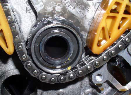
VVT base circle
Duration at .050 in. is a measurement of the movement the cam follower, in crankshaft degrees, from the point where it’s first lifted .050†off the base circle on the opening ramp side of the camshaft lobe, to the point where it ends up being .050†from the base circle on the closing ramp side of the lobe.
Lift is the measurement of the height of the lobe above the base circle. Multiply lobe lift times the rocker-arm ratio (in cases where rocker arms are present) to establish valve lift. For example, a 0.350-in. lobe times a rocker ratio of 1.5 equals a gross valve lift of 0.525 in. Until the advent of variable valve timing (VVT), camshaft timing, lift, duration, and overlap were all fixed values determined by the location and shape of the lobes on the camshaft when the cam was ground. What’s more, the profiles and locations of the lobes were ground to optimize power within a certain rpm range.
Passenger vehicles typically spend most of their time from idle to about 3,500 rpm with occasional bursts to 5500 rpm, so automotive camshafts are usually ground with relatively low duration and overlap to increase low-end torque. A cam with minimal duration and overlap also creates lots of intake vacuum, which allows for good throttle response but also creates power losses as the pistons struggle to pull air past the nearly-closed throttle plates.
A good mid-range cam gives up some low-speed torque and peak high-speed horsepower to obtain a wider power band in the middle rpm ranges. Because of these factors, most cams (including those for high performance) are still a compromise. The breathing characteristics of any camshaft work best within a fairly narrow rpm range, and everything on either side of that range is less than optimal.
Enter the Variable Valve Timing Concept
The simplest form of VVT is cam-phasing, whereby the phase angle of the camshaft is rotated forward or backward relative to the crankshaft. Thus, the valves open and close earlier or later; however, the camshaft lift and duration cannot be altered with a cam-phasing system. Mercedes-Benz began utilizing cam phasing in production cars in the 1980s. Achieving variable duration on a VVT system requires a more complex system, such as multiple cam profiles or oscillating cams, which we see on some of the latest Mercedes-Benz vehicles. This article will deal primarily with the M272 and M273 engines and those with similar valve configurations. These have been in production for some time now and we will look at those engines that have begun to acquire substantial mileage and the scenarios you will see in the field.
 Here’s how the cam phaser lines up with the cam gear. |
|
Location of control valve, intake valve illustrated 1. Pulse wheel 2. Control Valve 2/1 Circlip 3. Vane-type adjuster 4. Intake camshaft Y49/4 Left camshaft intake solenoid Y49/5 Right camshaft intake solenoid |
The introduction of the M272 brought some changes, notably:
- Four-valve continuously-variable camshafts, intake and exhaust ( DOHC)
- Two-stage intake manifold
- Turbulence flaps in the intake ports
- No EGR valve – both cams adjust to reduce NOx
- Four cam adjusters
- Four cam sensors
- Four impulse wheel triggers
- Four camshaft control plungers
- Intake cam is chain driven and drives exhaust cam via gears
The camshaft timing adjusters are vane-type oil pressure-controlled adjusters that are continuously variable. Since oil pressure is one of the control factors, the quality of the oil and the history of maintenance is paramount to the longevity of the components. The use of non-Mercedes-Benz-approved engine oils and filters, or infrequent oil changes can lead to a host of problems the technician will see in regards to this system. That being said, when faced with possible camshaft timing issues one of the most important things a technician can do in a preliminary evaluation is a visual inspection of some of the internal components of the engine. Granted, sometimes this will involve removing a valve cover, but it may save you a lot of heartache in the long run. Inspection of the underside of the oil filler cap can sometimes give you an indication that further inspection for sludge build-up is warranted.

The solenoid location from the workshop manual.
On the intake side of things, the camshafts can advance from 4 deg. BTDC up to 36 deg. ATDC. The exhaust camshaft can retard from -20 deg. BTDC to +20 deg. ATDC.
Each of the four camshaft adjusters has an impulse wheel mounted to its front, and they each have a different part number. The openings of the impulse wheels help the ME (Motor Electronics) determine the camshafts’ exact position. It is important to note that the impulse wheels can only be used one time! If new impulse wheels are not used, the pins could shear off causing extensive damage to the adjusters.
Four Hall Effect sensors are mounted on the front of the engine, one for each camshaft. Right and left camshaft signals are staggered and have a quick-start function capable of detecting a cam position with a stationary engine. The crankshaft revolutions are counted by a single Hall Effect sensor. There are also four timing control solenoids, one for each camshaft, which are pulse width-modulated by the ME and push against the camshaft control plunger when activated.
How it actually works
As noted previously, the intake and exhaust camshafts can be adjusted continuously by 40 deg. The infinitely-variable adjustment of the camshafts is carried out by patented, electro-hydraulically operated vane adjusters mounted on the front end of the camshafts, with integrated control valves. Solenoids are located in the front of their respective camshafts. The solenoids actuate the control plunger on the vane-cell adjuster according to the performance map-related duty cycle. Depending on their position, more or less oil pressure flows from the hollow camshaft to the oil galleries of the vane-type adjuster.
The solenoids for camshaft adjustment are designed as proportional magnets, i.e. the direction of the armature and thus the position of the control plunger in the vane-type adjuster are dependent on the intensity of the current in the coil. Occasionally you will see failures in these magnets to properly advance or retard their respective camshafts. Generally, DTCs will be set for these to aid in proper diagnosis. We have provided some actual scenarios from the field showing what you might run into in the course of your service work. The solenoids before the camshafts are actuated by the ME control unit at the ground end by means of a PWM signal (150 Hz). The voltage supply for the solenoid is from circuit 87. The vane-cell adjusters are actuated according to the performance map related to duty cycle. The maximum current (duty cycle 100%) is emitted for a short time (about 0.5 second) for rapid adjusting of the anchor. A hold-in winding voltage with a small duty cycle is then set afterward. Pressurized oil flows out of the hollow camshafts into the vane-cell adjuster. The camshafts adjust themselves to the respective direction of rotation. The inlet camshafts adjust to advance, while the exhaust camshafts adjust themselves due to their reversed direction of rotation to retard. Depending on their position, the oil volume in the vane –type adjusters is controlled. This takes place through differently arranged holes in the control plunger as well as through oil ducts in the vane-cell adjusters.
The adjusting range is limited by the design of the vane-cell adjuster mechanically. If the solenoids are no longer actuated then resetting takes place against the direction of rotation. Each camshaft position is detected by a camshaft Hall sensor. Once the requested adjustment has been achieved, then the respective solenoid will be actuated in such a way that oil galleries in the vane-cell adjusters are closed.
Common fault code scenarios

These solenoids have been leaking for too long. They will have to be cleaned and evaluated for the leak source.
When confronted with complaints of lack of power or performance, which most likely will be accompanied by a MIL (Malfunction Indicator Lamp, also known as the Check Engine Light) on, a few common scenarios will turn up in the field. One scenario will be that the camshaft adjustment solenoid is leaking oil and no fault codes are stored in the control module. There are usually two areas in which you can find the leak. One will be the sealing ring between the solenoid and the cylinder head, in which case you would replace the sealing ring. If the leak is at the electrical connector, then the operation would be to replace the solenoid.
You may be confronted with fault codes 0059, 0060, 0063, 0064, 0271, 0272, 0275, and 0276. These codes are generally caused by a malfunctioning camshaft adjustment solenoid. Using Star diagnosis, XENTRY, or compatible diagnostic equipment, proceed with the proper evaluation of each DTC. The solenoids are all the same, so switching their positions can be a valuable aid in determining the solenoid adjuster at fault. If you suspect a faulty solenoid, simply swap it with one of the others and observe your data to see if the fault followed.

It is sometimes hard to see, but the numbers should line up exactly in the center of the windows.
One of the more common scenarios is when the MIL is on and DTC 1200 and/or 1208 is present. When the fault memory is erased and the engine is restarted, the fault codes return immediately. This is due to the positioning of the timing chain-driven camshaft and its relationship to the crankshaft. The cause may be a worn sprocket on the balance shaft on the M272 engine, or a worn idler gear on the M273. To confirm, you will need to do a quick cam timing check. Remove all the camshaft hall sensors and rotate the crankshaft balancer to the 305 deg. mark with the front cover pointer. Now, you can check the impulse wheels’ stamped numbers and see if they are properly lined up. Note that you may have to rotate the crankshaft more than one revolution to see the stamped numbers. The numbers on the impulse wheels should be centered perfectly in the camshaft hall sensor openings. If you find that they do not line up properly, it is time for some disassembly for further inspection.
Notice how the new gear compares with the old one.
Remove the timing case cover and perform a visual inspection of the teeth on the balance sprocket or the idler gear, depending on which engine you are working on. The teeth will most likely show some wear as in the photo. This wear is causing the misalignment of the camshaft timing and your DTCs. In rare cases, a stretched timing chain might be the reason for the fault codes when the sprocket doesn’t show any evidence of wear.
If the gear is worn, it will require replacement of the balance shaft on the M272 engine, or the idler gear of the chain drive on the M273.
It is important at this juncture to refer to the previous notes in this article about paying particular attention to the overall condition of the engine in regards to proper care and oil quality. Sludge build-up due to infrequent oil changes or the use of oil that doesn’t meet Mercedes-Benz standards may make this a candidate for a replacement engine. Many shops at this stage opt for a genuine remanufactured engine from Mercedes-Benz in order to give customers the best return for their investment in the repair. It is critical to have this discussion with your customer to be assured the repair will be one that results in long-term satisfaction.
The following steps can be followed if it is determined that a satisfactory result can be obtained by repairing the engine as per WIS instructions for replacing the balance shaft or idler gear:
- Replace balance shaft or idler gear as per WIS instructions — the counterweight on the M272 engine must also be replaced. The balance shaft and counterweight are specific to engine designation, so order by VIN.
- Replace the oil pump.
- Replace the chain tensioner. A note of caution: chain tensioners must be installed only after the cylinder head covers have been replaced. Failure to do so will result in the overtightening of the chains and engine damage. Chain tensioners are one-time use only because during their removal the pressure pin is pressed into the end position, and the thrust pin latch prevents the return stroke. This would overstretch the timing chain on reinstallation.
- Change the engine oil and filter using the appropriate oil from M-B sheet 229.5.
- Drive the engine at high load and rpm for about 15 miles.
- Change the engine oil and filter once more using the appropriate Mercedes-Benz- approved oil and filter.
- Replace all four of the camshaft adjustment solenoids.
Note: Cylinder heads do not need to be removed.
Although these systems have evolved and will continue to do so in terms of efficient valve timing, lift, and duration, paying attention to the details when confronted with high-mileage vehicles will pay off both for you and your customer. Proper attention to customer concerns and DTCs, and consulting the latest StarTek information will assure you of successful diagnosis and repair of these systems.


0 Comments