
The basic geometry is the same as it’s always been, but the means of making adjustments and recalibrations sure aren’t.

Even when we get fabulous electrics such as this Vision Mercedes-Maybach 6 Cabriolet, the essentials of wheel alignment — toe, caster, and camber — will still be with us.
Wheel alignments are nothing new, but how you go about them has evolved over the years. Long ago, Mercedes-Benz used eccentric washers for camber, and the company still uses them in some models for rear toe. Later models used bolt kits, where you got to pick one of three possible settings.
Modern Mercedes-Benz cars use eccentric control arm bushings, again with a choice of three settings. While not a lot different from those bolt kits, now we have to be darn sure of the position for those bushings since the effort to make a change is far higher than with bolts.
, the essentials of wheel alignment — toe, caster, and camber — will still be with us.")
Even when we get fabulous electrics such as the Vision Mercedes-Maybach 6 Cabriolet (see cover), the essentials of wheel alignment — toe, caster, and camber — will still be with us.
This article is written for technicians who already know how to perform a wheel alignment. Unlike past models, starting with the SL-Class (R231), newer Mercedes-Benz models now use eccentric bushings to adjust camber. We’re going to take a careful look at how to calculate the correct bushing positions for a wheel alignment simply because there’s a lot of work involved in pulling the control arm, swapping bushings, and reinstalling everything — and nobody wants to do that more than once unnecessarily.
Before we start, a brief review of the three main alignment settings is in order:

In the old days, eccentric washers were used for adjustments, allowing for perfect stepless setting. Most Mercedes-Benz cars still use these for the rear toe adjustment.
Toe is the inwards or outwards splay of the wheels. Stand up and look at your feet: In most people, their toes are farther apart than their heels, which is negative toe, although some of us have their toes closer than their heels (pigeon toed?), which is positive toe. In rear-wheel-drive cars, a small amount of negative toe is a typical setting, enhancing straight-line stability.
In Mercedes-Benz vehicles, front toe is adjusted by changing the effective length of the tie rods by turning the threaded ends. Rear toe often uses eccentric washers at the rear control arm mountings. Toe has the greatest effect on tire wear, and therefore needs to be set quite precisely. Since the adjustment process is simple and inexpensive for the manufacturer on the assembly line, it is unlikely to change.

The newest models from Mercedes-Benz now use eccentric bushings for setting caster and camber. Unlike eccentric washers and bolt kits, pressing in a new bushing is supposed to be a one-time event, so getting the right position the first time is essential.
Caster is the forward or rearward tilt of the wheel axis relative to vertical. Think of the casters on a typical desk chair: The axis is tilted very far backwards so the wheels pivot and drag behind the direction of motion, which is positive caster. Because of the beneficial self-centering effect of positive caster, the typical car has a setting of several degrees of positive caster. Caster adjustment is relatively uncommon — if it is out of tolerance, it often points to bent or damaged components, which need to be replaced. Caster is adjusted by moving the top of the strut mounting forwards or rearwards, and is greatly affected by rear ride height.

Just as it’s been since the beginning of the automotive era, toe, caster, and camber are the three main alignment settings. Knowing which direction is positive and which is negative is now more important than ever before.
Camber is the inwards or outwards tilt of the wheels when viewed from the front. If you stand with your feet spread far apart so that your legs tilt inward, that is negative camber (typically employed in race cars for enhanced cornering). Camber has some influence on tire wear, but more influence on handling, with a small negative setting being typical, which helps tire grip when in a curve. Front camber is adjusted by moving the mounting points of the lower control arm or spring arm inward or outward.
If you have been performing wheel alignments for a while, you know all this, but the important part of the discussion above is whether an angle is positive or negative. Toe and camber are generally negative, while caster is positive. As for toe, nothing is really new, so we won’t discuss it any further. The settings you really need to pay attention to now are caster and camber.

This shows the inter-dependence of the wheel adjustments in an older Model 221 S-Class, which uses a bolt kit. Even though the torque strut is used to adjust caster, it still has an effect upon camber. These effects need to be considered using a thought experiment to be sure you position the adjustment bushing in newer models correctly.
Due to the geometry of the front suspension, caster and camber have an effect upon each other: If you move the front of a lower control arm outwards to increase negative camber, the wheel is also being moved towards the rear of the vehicle slightly, which causes a positive increase in caster. Changing the camber has an effect upon caster, and vice-versa, so this effect must be considered when calculating the adjustment you want to perform. Unlike eccentric washers, or even bolt kits, now when you decide to make a camber adjustment you need to swap out one or both bushings, which isn’t a trivial amount of work. Worse still, if you guess wrong, you’re going to have to do it over.
That’s what the rest of this article will help you do: eliminate all the guesswork so you can do the work with the least effort and best effect.
In the best-case scenario, your wheel alignments are being done on a Mercedes-Benz-approved MKS rack, following the work procedures detailed in the Workshop Information System (WIS). The MKS rack – unrelated to the actual alignment machine that happens to be mounted to it – provides a precision surface on which to perform a wheel alignment. If just a few millimeters (!) out of level, you’re going to get wrong data and possibly mis-align the wheels. So if you want your customers happy, use the right equipment. Mercedes-Benz dealers are required to check their MKS rack’s calibration often, and have it recalibrated every 6 to 12 months at a minimum.
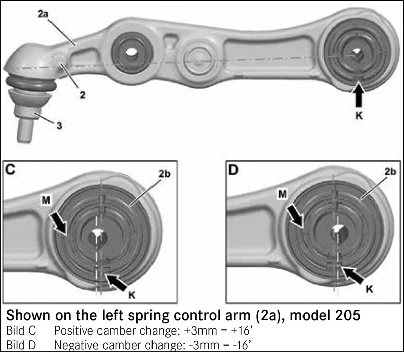
A portion of WIS document AR40.20-P-0263LW “Adjust camber and caster at the front axleâ€. Cutout “D†shows the hole in the eccentric bushing positioned further from the ball joint, and the text tells us this will change camber by 16’ towards negative (-16’).
Our local ISP shop can’t afford an MKS rack and alignment machine (the volume just doesn’t support one), so our friendly Mercedes-Benz dealer does the work when we need it. It keeps one technician busy all day doing nothing but alignments, and it has a second machine that’s used almost all day as well, so not only do they have the right equipment, they have a tremendous amount of experience in the Mercedes-Benz procedures.
We’re going to assume you know how to prepare for and perform a proper wheel alignment, so we won’t cover the steps here. If you don’t know, you need to learn how: Just following the alignment machine’s prompts without, say, checking tire pressure and condition, suspension and vehicle condition, vehicle loading, properly settling the suspension, or even the all-important before-and-after road tests, will surely lead to poor results and likely a customer complaint. Nobody wants that.
For this example, we’ll be using a Model 205 C-Class, but the concepts are the same for all models. After some suspension work, we set the car on the rack and found the right front camber to be at 0° 22’. We can look up the camber specification using WIS in Group 40, but the alignment machine gives us the specification as 0° 3’ with a maximum permissible deviation left/right of 0° 11’, so we are definitely out of specification here.
We need to bring the right front camber in by ideally 0° 19’, but anything from 0° 14’ to 0° -8’ is close enough. For the purposes of this example, we’re not considering the total camber tolerance of +0° 15’ to -0° 27’, we’re focused on cross-camber relative to the left front.
Our dealer’s parts team told us we can buy either standard (as part of the arm assembly) or eccentric bushings (individually) for both the strut rod and the spring control arm. It is clear that we need something to change the camber, but buying two eccentric bushings would be a waste of money.
Looking at WIS document AR40.20-P-0263LW “Adjust camber and caster at the front axle,†we see that changing the strut rod bushing lets us adjust caster, while changing the spring control arm bushing lets us adjust camber, so that’s the part we need to order. If you’re still not sure, take a moment to think about which direction you need to move the wheel – in or out, forwards or backwards – and then figure out what that movement will do to camber and caster. Will it increase or decrease, and is that what you want? It might be a little confusing to think in three dimensions like that, but taking the time for the mental exercise could save you some grief later.
We remove the spring control arm from the car and bring it to our hydraulic press. Using WIS document AR33.15-P-01700-2LW “Insertion/extraction of the rubber bushing on the track control arm†(linked from the previous document) and its recommended Mercedes-Benz special tools W220 589 06 43 00, W211 589 00 43 00 and W221 589 00 43 00, we find the perfect combinations of sleeves, punches and counter-holders to make extraction and insertion of the bushings actually enjoyable in its ease and simplicity.
But, as we get ready to press in the new eccentric bushing, we pause: Which way should it face? Looking at the first document again, we see the spring control arm can be positioned for two camber adjustment possibilities, of +0° 16’ or -0° 16’. Since we need to reduce camber – make it less negative – we check the document again and see that the eccentric bushing needs to be pressed into place with the eccentric hole farther from the ball joint, as shown at “D†in the WIS spring control arm image. We do that, put the car back together, recheck and find the right front camber to be 0° 6’, almost dead on the mark.
Before we celebrate our success, we really should think about ride height. If we consider the condition where the rear ride height is just an inch low, we can see how that would push our measured caster nearly a full degree towards zero. The point is that failing to consider ride height can lead to dramatically wrong alignment settings.
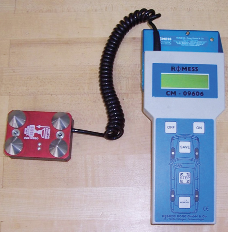
Measuring ride height is critically important since ride height determines the specific alignment settings. Mercedes-Benz dealers use this ROMESS gauge along with their precision MKS alignment rack to ensure the highest levels of accuracy.
Before even thinking about ride height, make sure to adjust the vehicle loading to “ready-to-drive†condition. This means emptying the vehicle of all cargo, making sure the spare tire is present and in place, and the fuel tank is filled about halfway, again as explained in WIS. As you might imagine, an extra hundred pounds in the trunk could really throw things off.
Ride height is a critical aspect of any alignment. In most models, measuring the ride height is mandatory to calculate the correct alignment settings, particularly caster. In some models – those with active suspensions – you need to calibrate the ride height sensors to ensure the suspension is at the right place for an alignment. Let’s take a look at the four major suspension types you’ll encounter and what you need to know about them.
Steel Suspension
A “steel†suspension is characterized by steel springs or torsion bars at the front and/or rear, coupled with tradi-tional shock absorbers or dampers. A leaf-spring rear is also considered a steel suspension. Only the spring carries the weight of the vehicle. The ride height of a steel suspension is adjusted using rubber shims of vari-ous thicknesses inserted between the spring and the spring seat.
Self-leveling suspension
Certain models are equipped with a self-leveling suspension at the rear, for example, in a station wagon. Depending on the specific system, hydraulically- or pneumatically-actu-ated rear struts automatically adjust vehicle ride height to compensate for vehicle load, using a suspension-mounted ride height sensor.
The ride height in vehicles with these systems is adjusted using rubber shims as with a steel suspension, followed by adjustment of the level control system as detailed in WIS. The basic ride height must NOT be set by adjusting the sensor control point, as this produces an incorrect system calibration.
MacPherson Strut Suspension
A MacPherson strut suspension is characterized by the use of an integrated load-bearing coil spring surrounding a damper, which is a structural member of the strut assembly. The strut is part of the wheel-locating structure.
The ride height of a MacPherson strut suspension is generally not adjusted. If the ride height is not within the published tolerances, the spring and/or spring mountings must be replaced, or there could be body damage. However, in some cases a small amount of adjustment can be found by loosening and retightening the strut mounting bolts.
Airmatic & ABC suspension
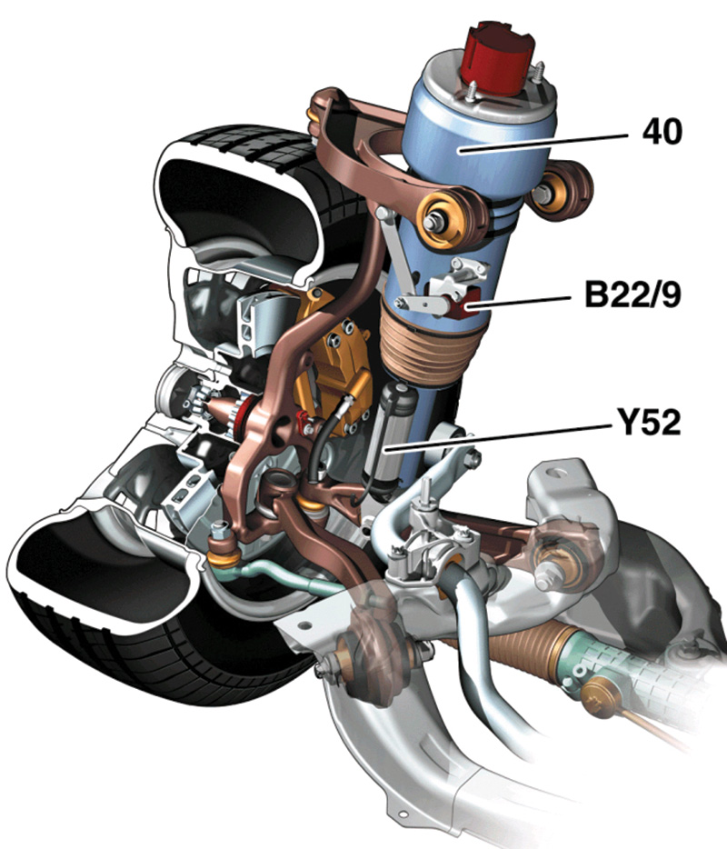
An AIRMATIC suspension strut (40), the suspension level sensor (B22/9), and the control valve (Y52). Before performing a wheel alignment on a vehicle equipped with AIRMATIC, you need to raise and lower the suspension once. In some cases, you may also need to recalibrate the level sensors.
Vehicles with AIRMATIC suspension have semi-active pneumatically-adjusted load-bearing suspension struts (say that three times fast!) that have adjustable damping. The vehicle ride height and suspension characteristics vary according to vehicle operating parameters, such as vehicle speed and driver selection.
Vehicles with Active Body Control (ABC) have active load-bearing suspension struts that act very quickly to adjust the vehicle ride height and suspension characteristics, again according to vehicle operating parameters such as cornering, braking, acceleration, and road surface characteristics, as well as driver settings.
Steel and Macpherson suspensions need to be settled before starting a wheel alignment. We do this by jouncing the car – pressing down forcefully and allowing an untouched rebound – at each of the four corners of the vehicle. This also applies to the self-leveling rear suspension, but there we need to first verify the suspension basic level is set correctly by measuring as explained in WIS.
In AIRMATIC and ABC vehicles, the suspension must be raised and lowered using the suspension system before performing a wheel alignment. Note that in USA-produced SUVs (e.g., W166), the system requires wheel speed to be non-zero for the suspension to lower. Drive the vehicle slowly (approx. 10 mph) over a short distance.
It is not always required to actually calibrate the AIRMATIC and ABC suspension for a routine alignment, but if the height readings seem out-of-line, or you’ve replaced a major component (control unit, level sensor, spring link, or upper link arm), then a ride height sensor level calibration should be performed. Note that it is not necessary to recalibrate ride height when only a strut is replaced.
A level calibration in an AIRMATIC or ABC vehicle allows the control unit to match the level sensor readings to the actual ride height. An uncalibrated sensor still provides level readings, but the control unit does not know how to relate that to the actual vehicle ride height.
Ride height calibration is performed using XENTRY, a level MKS rack, and the ROMESS inclinometer. Although the exact details may vary by model, the general procedure is:
- Place vehicle on a level MKS rack.
- Raise and lower suspension completely.
- Enter the Level Calibration routine in XENTRY and follow the steps.
- Set the ride height to the nominal values (within the green zone) as shown on the screen.
- Measure the ride height angles using the ROMESS gauge and enter these into XENTRY.
- The ride height should be calibrated. It is possible that the calibration is unsuccessful. In these cases, perform the calibration again.
As we said in the first paragraph, wheel alignments are about the same basic things as ever, but advances in suspension technology and adjustment methods have certainly changed the game enough to take notice. If you take anything from this article, let it be that just a little bit of careful thought about how you are moving the wheel around while doing an alignment will let you hit the numbers every time, to your and your customer’s benefit.
Download PDF 〉


0 Comments