

The camera in the Nissan RearView Monitor system is used to help drivers with backup maneuvers. Here are a few tips for diagnosing problems and restoring system functionality.
The Nissan RearView Monitor is a single camera system that gives the driver an in-dash view of what is directly behind the vehicle. The following description and all repair procedures mentioned in this article apply only to the 2011-14 Murano Z51, unless otherwise noted. Other Nissan models and build years may include rear view monitor systems that feature different camera and control technologies, and require different diagnostic and repair procedures. Refer to your Nissan repair manual for application-specific information for the vehicle you are repairing.
How It Works
 showing the direction the vehicle will travel, based on how the steering wheel is positioned. Guiding lines indicate the vehicle width (5) and distances to objects with reference to the vehicle body line (A). Green lines mark distances of ten (4) and seven feet (3), a yellow line (2) warns that the vehicle is within three feet, and a red line (1) indicates there is only a 1.5 foot space remaining between the vehicle and an object behind it.")
When the gear selector lever on the 2011-’14 Murano Z51 is in Reverse, the Nissan RearView Monitor system displays predicted course lines (6) showing the direction the vehicle will travel, based on how the steering wheel is positioned. Guiding lines indicate the vehicle width (5) and distances to objects with reference to the vehicle body line (A). Green lines mark distances of ten (4) and seven feet (3), a yellow line (2) warns that the vehicle is within three feet, and a red line (1) indicates there is only a 1.5 foot space remaining between the vehicle and an object behind it.
When the transmission is shifted into reverse, the rear view camera in the 2011-14 Murano Z51 receives power from, and is operated according to, commands generated by the AV (audio visual) Control Unit. The rear view camera sends its images to the AV Control Unit.
The AV Control Unit then generates fixed guide lines and predictive course lines in red, green or yellow, and overlays them onto the rear view images. It sends this combined visual to the in-dash display unit. The fixed guide lines give the driver a backwards-facing view, showing in real time exactly where the vehicle is relative to objects immediately behind it. The predictive course lines project where the vehicle is headed based on input to the AV Control Unit from the steering angle sensor.
The AV Control Unit is connected via CAN communication to the ECM and the rear camera and in-dash display unit.
When the transmission is in reverse, lines of different colors on the monitor indicate the distance from objects behind the vehicle. Using the familiar green, yellow and red colors of a traffic light, the lines start at ten feet away and give an increasing sense of urgency as the vehicle’s predicted travel path puts it closer to nearby objects. A red line screams “Hey! You’re only 1.5 feet away!â€
It doesn’t actually scream at you, of course. Perhaps that is one reason for the system’s immense popularity. Unlike your significant other or co-worker in the passenger seat, checking the rear view mirror and not-so-secretly applying the brakes, Nissan’s RearView Monitor helps you back up without passing judgment on your maneuvering skills.
A Proud History
Nissan’s Infiniti luxury division was the first to incorporate backup camera technology in a production vehicle for the North American market. The company introduced its RearView Monitor system at the 2000 New York International Auto Show, with North American market launch in March 2001 as optional equipment on the 2002 Q45 sedan.

The backup camera is housed in the rear liftgate or decklid, depending on the Nissan model and year. Shown here is the liftgate of a 2013 Murano.
RearView Monitor technology is now a standard feature on select vehicles across the Nissan line, and is available on every Nissan model. The technology is popular with safety-conscious consumers, and thanks to cell phones, the size and cost of high-resolution cameras has come down significantly since 2002. The only thing needed for the rapid spread of on-vehicle cameras to non-luxury models was a way to display the images. Thus today, on almost any Nissan model that is equipped with an in-dash screen for navigation and entertainment systems, a RearView Monitor camera is either standard or optional.
Rear Collision Likely Affects RearView Monitor Performance
.")
For collision repairs, detailed specifications and measurement information for liftgates, decklids, and other components are available in the Nissan service manual section “BRM†(Body Repair Manual).
The camera is always housed in the rear liftgate (tailgate) or decklid, depending on the vehicle model. Any collision that affects the alignment of the liftgate or decklid will likely alter the direction or angle in which the camera is pointed, destroying the accuracy of rear view imaging information provided to the driver.
Additionally, any wiring fault or damage to control modules for the audio visual system, of which the backup camera technology is a part, can cause performance problems with the RearView Monitor.
The Right Stuff
Repairs to a liftgate or decklid that contains a rearview camera require precision alignment of the repaired or replaced component. Aftermarket or recycled liftgates may have differences in build specifications that result in issues with camera alignment and performance.
Non-symmetric shape, variations in size due to less stringent aftermarket production tolerances, and fitment issues with hinges and other mounting hardware are just a few of the causes of difficulty in achieving a proper alignment of the liftgate.
For all of these reasons, repair or replacement of liftgate or decklid components should only be performed with Genuine Nissan replacement parts.
It is important to note that the inner and outer panels of the liftgate in the 2011-14 Murano are made of polypropylene. You cannot use a hammer and dolly to work the camera housing into the proper alignment.
Some non-OE liftgates may come without pre-drilled holes for camera installation. This forces the body shop to cut the opening, introducing potential measurement or placement error, not to mention requiring time-consuming extra labor. When collision repairs are necessary, Nissan North America strongly recommends that any repairs use Genuine Nissan replacement parts designed for the specific Nissan vehicle being repaired.
A Key Post-repair Step
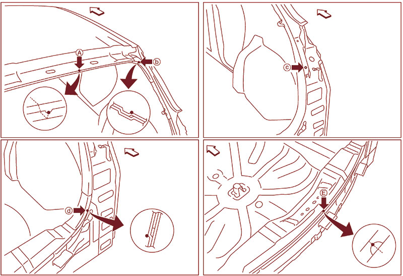
The Genuine Nissan replacement liftgate is designed to fit perfectly at several required measurement points, including the roof indent marking the horizontal center (A), the rear pillar main joggle (B), the vertical center in the rear pillar (C), the rear fender brace joggle (D), and the horizontal center positioning mark in the upper rear panel (E) above the bumper.
Because the control module must know not only the direction and angle of the camera, but also its input and output specifications and communication protocols, the camera must be re-initialized and calibrated any time a related wiring harness has been disconnected. Even if you disconnect the camera’s wiring harness only to move it for access to some other component, or to protect it from welding heat or some other nearby repair operation, you must re-calibrate the system in order to restore its functionality.
Nissan has issued a Collision Position Statement (NPSB-16-600, June 20, 2016) making post-repair calibration mandatory after removal or replacement of any camera or the part in which it is mounted, including a liftgate, decklid, front grille or door mirror. If you’re not sure whether the vehicle you are repairing has a rear view camera, check the Nissan service manual section “AV†(Audio, Visual & Navigation System) for further information.
Multifunction Switch Diagnosis

Make sure the dash controls are working. Turn the ignition switch from OFF to ACC, then simultaneously press the “BACK†and “UP†switches and hold both for three seconds. Next, press each button on the Multifunction Switch to check its continuity.
Before we condemn the RearView Monitor system in the 2011 Murano Z51, let’s perform the Multifunction Switch diagnosis. On the in-dash control panel, press the “BACK†switch and the “UP†switch within ten seconds of turning the ignition switch from OFF to ACC and hold them for three seconds or more. A buzzer will sound, all of the indicators on the panel will illuminate, and an automated system self-diagnosis begins. Press each button on the multifunction switch to check its continuity. If the switch is functioning normally, a buzzer will sound with each press.

Manually diagnose communication functionality between the AV Control Unit and the backup camera by pressing the SETTING button while rotating the volume control 40 clicks or more in either direction.
Note that the Hazard and Disk Eject switches cannot be checked in this way. Cancel the test by turning the ignition OFF.
A manual diagnostic procedure, called “Confirmation/Adjustment Mode†offers a more detailed assessment of individual components in the AV system, including the rear view camera.
To begin manually checking that there is communication capability between the rear view camera and the AV Control Unit, start the engine and turn the audio system OFF. While pressing the “SETTING†button, turn the volume control clockwise or counterclockwise for 40 clicks or more.
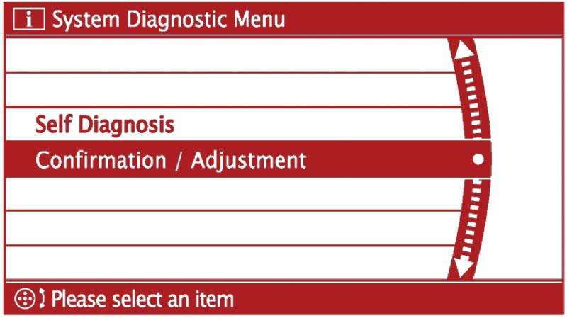
Use “Confirmation/Adjustment†mode in the system diagnostic menu to confirm the factory configuration of the backup camera, or to make adjustments as needed to restore RearView Monitor display functionality.
The system diagnostic menu screen is displayed. Select “Confirmation/Adjustment.†In this mode, you can check the factory configuration data relating to the rear view camera, adjust positioning of the guide lines that the AV Control Unit positions over images from the camera, and review any system error history.
Once in Confirmation/Adjustment mode, scroll down the screen to select the “Adjust Guide Lines†or “Display Factory Configuration†switches.
See your Nissan service manual AV & Navigation System section for additional details about using the AV Control Unit “Self Diagnosis†and “Confirmation/Adjustment†diagnostic modes. For example, you can adjust the appearance of colors on your in-dash display over a wide range beyond basic red, green, and blue and, of course, black and white. Just use the Nissan Color Spectrum and Gradation functions in the Display Diagnosis main screen.
Diagnose the AV Control Unit Using CONSULT III Plus
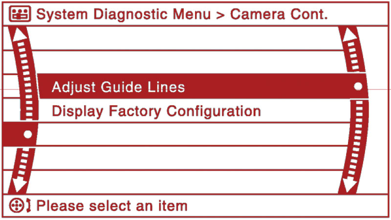
Select â€Adjust Guide Lines†to change the positioning of guide lines as they appear on the in-dash monitor.
Because the automated self-diagnosis mode is a switch operation, it cannot start if any malfunction occurs in the CAN communication circuit between the AV Control Unit and the multifunction switch. If the on-board diagnosis menu does not appear, if the in-dash screen does not display anything, or if the multifunction switch does not function, then you should perform a diagnosis using your CONSULT III Plus tool.

Use the Color Spectrum, Gradation, and White Screen functions in the Display Diagnosis main screen to adjust the appearance of colors in the in-dash display.
If there is a fault with the AV Control
Unit, CONSULT III Plus will display trouble code U1200, U1216 or U1310. Refer to the Nissan service manual section AV for diagnostic procedures.
Save Existing AV Control Unit Specifications — Before Removal
In addition to diagnosis and error history, CONSULT III Plus can identify the AV Control Unit part number, save the exact AV system specifications for the vehicle, and write the specifications to the new unit if the AV Control must be replaced. This is of critical importance because the replacement AV Control Unit is shipped without current vehicle specifications.
If you remove the existing AV Control Unit before saving its specifications and part I.D. number information, the vehicle will not recognize the replacement control unit. You need the AV Control Unit part number and vehicle specifications downloaded from the existing control unit and stored in CONSULT III Plus in order to configure the replacement unit. Without this data, you will not be able to initialize the replacement camera, and will thus not restore functionality to the RearView Monitor system.
On Camera
Checking the camera itself is pretty straightforward. If it is receiving the right amount of power from the AV Control Unit and not working, replace it.
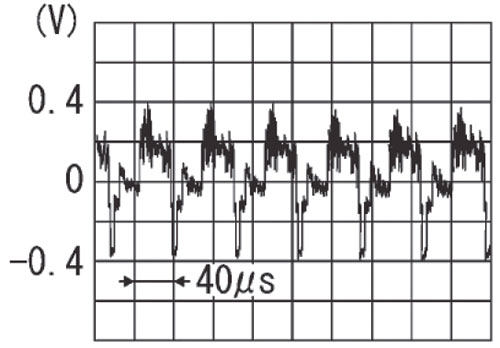
Reference values measured between the AV Control Unit terminal 62 (red wire) and ground, with the ignition on, in a 2011 Murano Z51 with base audio and color display installed should range between 0.4 and -0.4 V.
First, check continuity between the wiring harness connectors of the AV Control Unit (connector M173, terminal 73) and the rear view camera (connector D192, terminal 1). If there is continuity, you’re good. Next check between the AV Control Unit and ground. There should be no continuity. If you get a different result for either test, repair or replace the appropriate harness.
If the harnesses are OK, check the voltage supply to the camera. First, connect the AV Control Unit connector and the rear view camera connector. Turn the ignition ON. Put the transmission in Reverse. Check the voltage between the AV Control Unit harness (connector M173, terminal 73) and ground. If you don’t see 6.0 V, replace the AV Control Unit.
If you see the correct voltage on the ground side, check the camera image circuit. Turn the ignition OFF and disconnect the AV Control Unit connector and rear view camera connector. Make sure there is continuity between the control unit (connector M173, terminal 62), and the camera (connector D192, terminal 3). Then check to see that there is no continuity between the AV Control Unit and ground. If either continuity check shows the incorrect result, repair or replace the appropriate connector or harness.
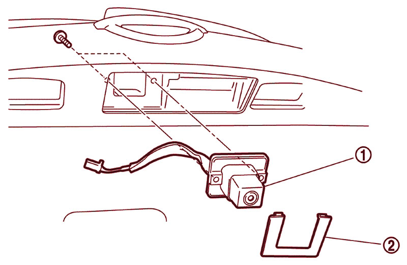
The rear view camera in the 2011 Murano liftgate is easily removed.
If all of the above checks out, suspect the camera itself. Re-connect the AV Control Unit connector and rear view camera connector, turn the ignition ON, and set the shift lever in Reverse. Check the signal between the AV Control Unit harness connector (M173, terminal 62) and ground. The voltage should fluctuate quickly between 0.4 and -0.4 V. If not, replace the rear view camera.
Installation is a bit more involved, although not difficult. In addition to physically mounting the camera, you must also lay out guide lines on the ground behind the vehicle and duplicate their position in the virtual image on the in-dash display. Using the “Confirmation/Adjustment†mode in the display unit, align the lines in the display with the guide lines on the ground, and press “OK†to save the settings to the AV Control Unit. Refer to the AV section of the Nissan service manual for the vehicle you are repairing for the exact “RearView Camera†installation procedure details.
After all repairs are completed, scan again for trouble codes. This will detect any new codes that have been set as a by-product of the repair procedures themselves. It will also confirm that problems identified in pre-repair planning have been properly repaired and that all vehicle systems are communicating as specified.
Now, smile for the camera.


0 Comments