What happens when the aftermarket parts source has difficulty finding the matching parts and the suppliers can not match the required parts? A disaster is a possibility and solvable.
This City Golf has an unusual engine configuration and not very common unless the least expensive Golf was purchased at the dealer. This specific Golf does not have the TFSI engine, but rather has the 2.0L port injected engine.
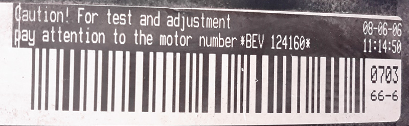
If you can remember the older Jetta, Golf, Beetle engines with a distributor or coil pack with port injection, we are on the same page. The engine in question is designated as BEV and nearly identical to the older 2.0L except there is a cam position sensor mounted behind the camshaft gear.
For all intents and purposes, this is the second vehicle we’ve encountered that experienced a similar issue with “replacement parts that didn’t meet the OEM requirements/specifications.†More on that vehicle later.
|
Customer Complaint: |
|
MIL lamp ON and long crank to start with the ABS lamp ON. |
|
Tools Required: |
|
|
Ross-Tech VCDS |
Your wife’s or girlfriend’s sewing needles |
|
90 amp Power Supply |
Camera and note paper |
|
Oscilloscope (PC or tablet) |
Torque wrench |
|
Detailed wiring schematic and repair instructions |
Cam gear counter holder |
|
TSBs pertaining to this type of fault (if any exist) |
Timing belt adjusting wrench |
Where to begin
Asking questions such as “Did you purchase this new and why is there a non OEM radio installed?†Answer: Purchased the vehicle used and that radio came with the vehicle. The radio is questioned because of how this style of radio communicates and if perhaps an inadvertent 12volt connection is attached to the “K†line (communications).
This vehicle however is not a full CAN vehicle and a poorly wired aftermarket radio can create communications faults. A poorly wired radio installation will drive the “K†line high and will certainly disturb communications and/or damage the scan tool. The original VCDS (Ross-Tech) is protected at the DLC and will NOT turn the green LED ON if the “K†line has a steady 12volts applied to pin 7 of the DLC. This has been documented many times. If in doubt, remove the radio and inspect the harness sooner than later. You have been warned!
Step 1: Identification
Gather the VIN, find the PR code and attach a power supply to the battery. Access the DLC and save the full autoscan with VCDS. Remembering a similar experience at another facility with the same engine code, there was a suspicion that caused us to make sure that the engine code matched this vehicle. As stated, this is a BEV engine. The scan produced faults in two controllers:
ECM cam position fault (with other suspects)
ABS sensor fault RR wheel
|
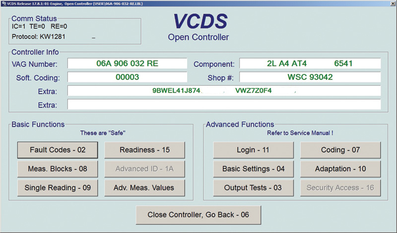
Address 01: Engine |
Labels: User\06A-906-032-RE.lbl | |
|
Part No: 06A 906 032 RE | ||
|
Component: 2L A4 AT4 6541 | ||
|
Coding: 00003 | ||
|
Shop #: WSC 93042 | ||
|
VCID: 72E048023EDB96D697-5102 | ||
|
9BWEL41J874xxxxxx VWZ7Z0F4xxxxxx | ||
|
6 Faults Found: | ||
|
17746 – Camshaft Position Sensor (G40) | ||
|
P1338 – 35-00 – Open or Short to Plus | ||
|
17766 – Cylinder 2 Ignition Circuit | ||
|
P1358 – 35-10 – Open Circuit – Intermittent | ||
|
16705 – Engine Speed Sensor (G28) | ||
|
P0321 – 35-10 – Implausible Signal – Intermittent | ||
|
17769 – Cylinder 3 Ignition Circuit | ||
|
P1361 – 35-10 – Open Circuit – Intermittent | ||
|
17763 – Cylinder 1 Ignition Circuit | ||
|
P1355 – 35-10 – Open Circuit – Intermittent | ||
|
17772 – Cylinder 4 Ignition Circuit | ||
|
P1364 – 35-10 – Open Circuit – Intermittent | ||
|
Readiness: 0010 1100 | ||
|
Address 03: ABS Brakes |
Labels: 1C0-907-37x-ABS.lbl | |
|
Part No: 1C0 907 379 L | ||
|
Component: ABS FRONT MK60 0101 | ||
|
Coding: 0004097 | ||
|
Shop #: WSC 00000 785 00200 | ||
|
VCID: 336E8D065141DFDE5C-5102 | ||
|
1 Fault Found: | ||
|
00287 – ABS Wheel Speed Sensor; Rear Right (G44) | ||
|
012 – Electrical Fault in Circuit | ||
Step 2: Fresh perspective
Clear all the fault codes and start from a fresh perspective. Noting the saved fault information, work from the top of the list, down. Also note that subsequent faults may also be attributed to a “root fault.†This case and remaining faults were created by the “root†fault. Only the ECM faults cleared temporarily. From past experience, the decision was to measure the cam and crank position sensors. No cam/crank synchronization = hard/no start.
Step 3: Action plan
Prepare the test by back-probing the cam position and crank position sensors with an oscilloscope. Maintain the attachment to the DLC with VCDS and monitor any fault changes over time. Depending on the equipment on hand, the choice was one laptop. The dual task was set up with VCDS wired via USB and a Bluetooth oscilloscope.
Note A: Graphics intensive programs and data logging can only run as fast as the equipment being used. For example, best to have dual core processors, solid state drives, maximum matching memory, USB 2.0 or greater ports, a clean and healthy operating system that is NOT infected with garbage, propaganda and running unnecessary sub-routines.
This ECM fault returned:
17746 – Camshaft Position Sensor (G40)
P1338 – 35-00 – Open or Short to Plus
Step 4: Follow the plan
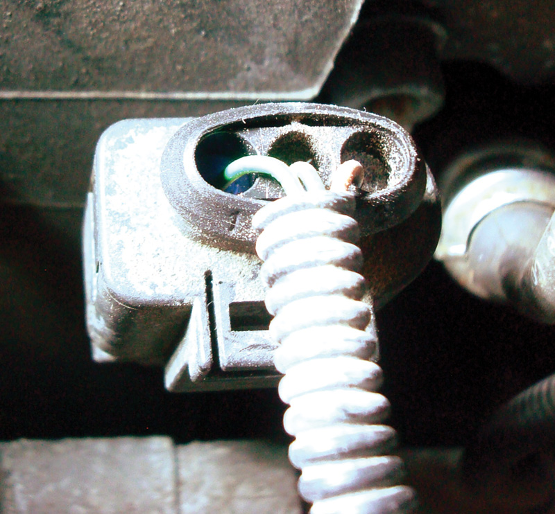
Begin by viewing the timing cover, cam/crank position connections with a current wiring schematic. Back probe with a small sewing needle at the cam/crank position sensors. Attach the oscilloscope of choice and record the sensor activity. Monitor VCDS RPM values and note any faults that may be recorded.
At times and if the sensor is defective while the engine is running, the fault will set immediately. There will also be another fault effect that will set the fault codes when the key is cycled once and the engine is started again. Any recorded fault should be considered as true and current. The captured screen images will offer details at a later time.
Note B: The oscilloscope will measure voltage over time. With the correct connection and oscilloscope setup, consider those images as true. Regard the scan tool faults as true but understand the scan tool only records what the controller is measuring. That measurement is only good if the software is not corrupt, damaged or defective. The oscilloscope measures the components in “real time†and if one component has an internal defect and also relies on a shared reference voltage, consider that circuit as a possible suspect as well. Look at the wiring schematic, do both sensors share the same 5 volt reference? Are there other shared connections?
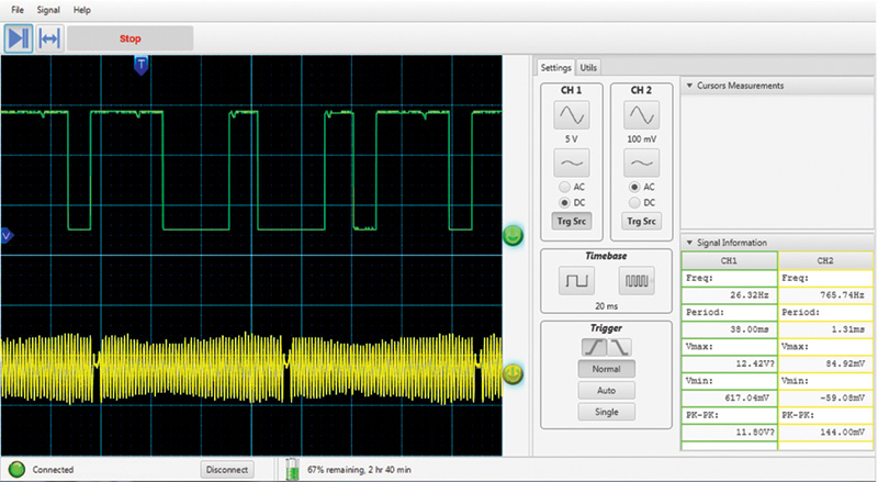
While monitoring with VCDS, start the oscilloscope and take your time to capture multiple images. This one is interesting because there is a repeat in the downward spikes at the cam position high side and the voltage did NOT hit the “0†mark as expected on the low side.
Note C: On the full captured oscilloscope screen, each spike measures 3 centimeters and repeated itself across the screen.
On the printed image, each spike measures relative to the view and repeats itself across the image.
Note D: This specific scope is being used because of portability and ability to be used on either a laptop or tablet via Bluetooth. This scope was never designed for automotive use so it was “adjusted†and tested with multiple 10x:1 cables and 20x:1 attenuators with 1000x:1 ignition paddles. There was access to 4 and 8 channel scopes but this was “the choice for the day.â€
More on this interesting scope later.
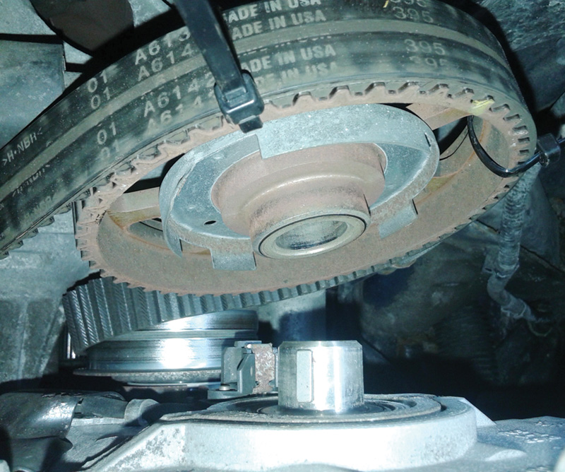
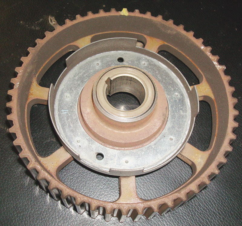
Remember the previous facility mentioned earlier? Their request was to replace the ECM because all of the tests lead to “Replace with known good ECM.†Not so fast. There was some previous wiring damage during their testing (stretched/opened connections while wiggling the ECM harness with a stall) and they lost the camshaft key that fell between number 1 ignition wire and the cylinder head. The last issue was a “defective†cam position sensor that was replaced days earlier and we suggested an OEM replacement.Using a metric plastic ruler, look at the repeating image in green. The measurement is relative to the screen or photo that you are viewing. Markers measuring the frequency could have been used on this scope but the proof is in the image. Removing the gear and an inspection offers more proof that rust played a major part in the fault with the sensor and cam gear timing windows and the sensor was not behaving as intended. There was quite a bit of rust removed with compressed air before the image was saved.
Step 5: Order the required parts
Order the parts, including cam position sensor and RR wheel speed sensor by using the year, make, model, engine code and VIN. Simple right?
Step 6: Re-order the required parts
Mark everything and remove the cam gear for inspection. There was a very large amount of rust flakes on the cam sensor. Opened the box for the cam position sensor – incorrect sensor arrived!
Reassemble and remove the Golf from the service bay!
Step 7: Get image examples
Get image of the cam position sensor and send image to the supplier. Supplier sends the sensor and maintains that “You have the wrong sensor.â€. The parts supplier was reminded of step 6.
It will happen on occasion that the parts listings are incorrect. This engine is NOT a TFSI engine and this engine requires a completely different sensor.
When the sensor arrives the following day, the process begins again.
Step 8: Re-order another replacement sensor
Install sensor. Attach and time the complete assembly, the cam gear windows …. will not pass through the opening of the replacement sensor! Call the supplier again and they still maintain the discussion “You have the wrong sensor†and remind them of step 6. Again and 5 minutes after they close, arrives with another sensor and this time, made the driver/manager wait! There was a dire need to help the manager “understand.â€
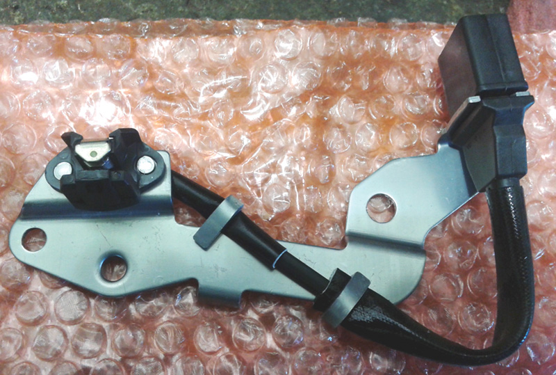
The image is of the correct style of sensor and the problem is where the rivets were placed for the sensor mounting. The aftermarket sensor is incorrectly aligned to accept the cam gear timing windows. Since the timing windows of the cam gear were hitting the sensor magnet, the gear would not mount completely onto the camshaft, binding the sensor and gear windows.
Step 9: Lessons learned
(a) The manager was surprised about the “parts listing†and matching images that were supplied. The required sensor is correct but the aftermarket version was of very poor quality and fitment. The lesson is relative to cost and time but after the “third†version arrived, this was not the best of experiences. The images proved the correct version.
(b) Adding to this discussion and something to think about. It is very rare when new replacement parts arrive incorrectly or defective. This specific Golf has a repair facility attached to it and that shop took the responsibility to order the needed parts. The lessen learned is that “When you touch it, you own it.â€
(c) A properly calibrated and connected oscilloscope never lies.
(d) The scan tool can only process data that is relative to the developed written software.
Step 10: Advice
Having heard/read many comments about this engine and replacement parts, this is the advice. A complete timing belt and hardware replacement is not required if the timing belt was not due. Cleaning the rust was the best option on both engines that were discussed. Scotchbrite or 3M pads work very well with compressed air and a dust mask.
If this article is read top to bottom, take notice that only the top cover and gear was removed. The timing belt was not due for replacement and all repairs took place at and behind the timing upper cover.
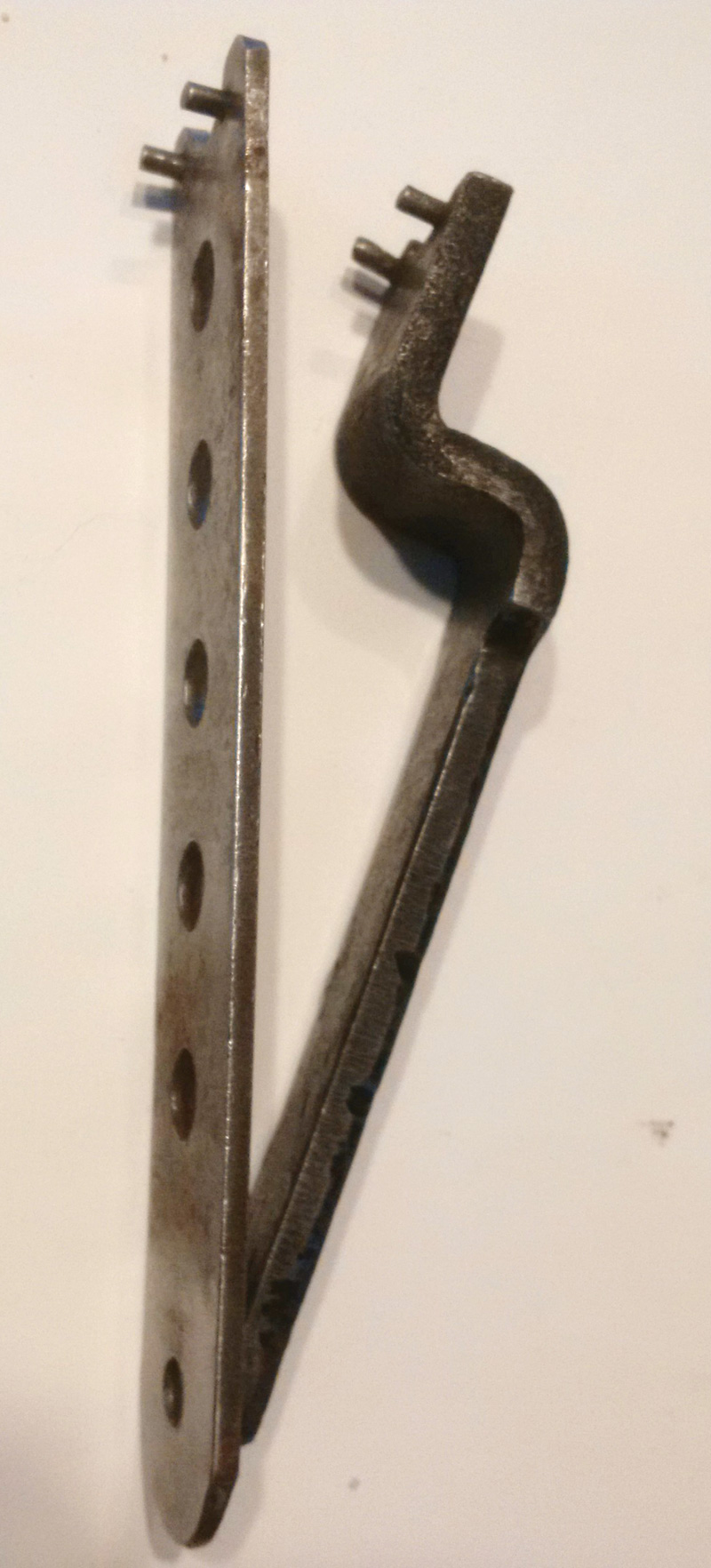
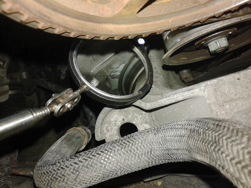
The timing belt adjuster was in perfect condition and there may be a problem if this procedure was accomplished with the mounting bracket to the engine block is in place. The tool required is the one on the left. Both are hand made tools and purpose made.
To adjust the timing belt, follow the service procedure, but some procedures are incorrect because of this unusual engine configuration. The procedure is to rotate the adjuster clockwise and view the alignment of the adjuster with a mirror.
|
Repeating |
|
Mark everything first (cam and crank). |
|
Follow the service literature and ensure the correct alignment. |
|
Adjust/align the wheel as is the image. |
|
Torque the wheel and cam gear as in the service literature. |
|
Start VCDS and clear all faults KOEO. |
|
Initiate VCDS again and monitor for faults. |
If all the correct replacement parts and procedures followed the plan, the previous faults as in the first scan will not be repeated. Look at that scan again, count how many faults were recorded with a “shorted or open†cam position sensor. Look at the schematic one more time and follow the path for the remaining sensors.
Remember: Search for all available TSBs and Dealer Campaigns associated with the vehicle.


0 Comments