
The roots of education are bitter, but the fruit is sweet.
-Aristotle
Whenever diagnostic sessions are not progressing well, the choices confronting shop owners and technicians can be daunting. Sometimes that vehicle may appear to “have a mind of its own,†but you won’t be able to read that mind without the right tools.
Here, we will explore the questions surrounding diagnostic equipment, including XENTRY, in an attempt to aid both the business owner and the learning technician. We’ll also look at how the DLC (Diagnostic Link Connector) is evolving at a rapid rate, and why good comprehension of the technology present in Mercedes-Benz vehicles is important.
OBD II and the DLC
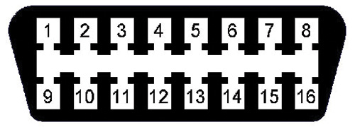
In 1996, OBD II was made mandatory for all vehicles sold in the U.S. (in actuality, for all of North America). That also meant that the modern OBD II connection (DLC) became standard. What is not standard are the “proprietary†connections to subsystems. OBD II was designed for engine and transmission diagnostics for the dealer or non-dealer technician, and it offers an array of “modes†that are related to emissions, testing, and diagnosis.
As the OBD II protocol matured, so did the array of modes and data that was accessed for profoundly complex engine management systems. Manufacturers are required to have their protocols available at the DLC. Those protocols will include CAN, VPW, PWM, and 9141-2 with ISO 14230-4. All North American vehicles will have access to one or more protocols via OBD II. There are, however, specific pins (terminals) at the DLC that are used by the manufacturer for its own purposes. OBD II has no access to those pins.
Well-designed modern OBD II devices can access far more data than the scan tools of the past, but that all depends on the capability of the suppliers and software developers to mathematically calculate the PIDS for display on the scan tool if those PIDS are mandated and available via the carmaker. Current OBD II tools have access to diagnostic data via high-speed CAN.
Even though a modern OBD II scan tool can access the CAN structure, it will have minimal access to the engine and transmission electronics network on any particular make, Mercedes-Benz included. The data will be only what’s required by regulations. There are many forms of OBD II scan tools, the most common being the ELM327 or ELM329 comprising a programmed microcontroller. The development of standard OBD II will continue to move forward, but access to Driver Assist Systems may not be possible.
Multiplexers and aftermarket equipment
There is an array of aftermarket tools that claim “complete access†to the vehicle diagnostic port including all internal networks and sub-networks. Unlike OBD II, these types of multiplexers may be able to access the complete network structure if the tool software and firmware is current and correct. Added as well is access and permissions to all installed networks and corresponding sub-networks. Complete and up-to-date access should include more than one CAN network attached to a gateway that supports multiple networks and sub-networks.
These tools, however, have inherited issues with accuracy, guided tests, and poor/insufficient documentation. One common issue is bi-directional control with future support. Another common problem is the association of workshop information with clear parts illustrations. A third typical issue is the association of data provided among controllers and the Central Gateway (CGW). The newest problem with these tools is access to the Ethernet structure. Welcome to DoIP.
XENTRY articles
Refer to these previous articles that have been published about XENTRY in StarTuned. They explain XENTRY performance and how to perform the tasks required within a professional workshop environment. They’re all informative:
- Newest Features of Versatile XENTRY Diagnostic System (March, 2016)
- The Intelligent Servo Module (December, 2016)
- Why You Need XENTRY (June, 2017 as a sidebar to Using WIS Efficiently)
- Control Unit Programming Now! (December, 2017)
XENTRY at work on communication errors
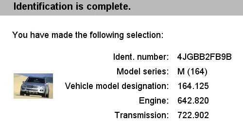
The copy, captions, and images throughout this article illustrate the complexity of the diagnosis of a mysterious real-world case concerning a 2011 ML 350 BlueTec. The customer’s basic complaint was a no-start, which only happened once. But there was more going on: all warning lamps were ON, the warning chime was sounding continuously, and the wipers turned on intermittently. Also, Direct Select was not operating and no selection was showing on the display. Finally, the no-start repeated.
Our diagnostic preparations included a “circle check†of the entire vehicle and testing of both batteries. We made sure our XENTRY was updated, attached a clean and stable power supply, and turned off all electrical consumers. Then, we used the VIN tab to identify the correct model, performed a complete Quick Scan, and saved the primary results.
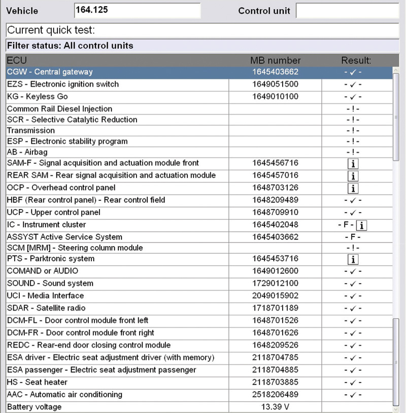
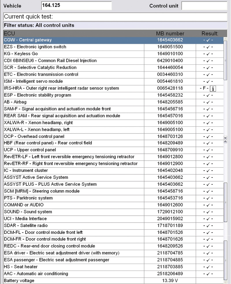
The following lists all the controllers found “after the fact†with a repair and rescan. This list identifies the controllers that were not communicating with XENTRY and were not in the Quick Scan list:
- ISM — Intelligent Servo Module
- IRS-HLA — Outer left rear intelligent radar sensor system
- IRS-HRA — Outer right rear intelligent radar sensor system
- XALWA-R — Xenon headlamp, right
- XALWA-L — Xenon headlamp, left
- RevETR-LF — Left front reversible emergency tensioning retractor
- RevETR-RF — Right front reversible emergency tensioning retractor
- ASSYST PLUS — Plus Active Service System
There are eight controllers off-line and the total count is 36 for this model.
HINT: If there is no M-B number, the controller was never fully interrogated/accessed.
Using the print feature of XENTRY, save the entire initial scan and read the complete document. The investigation begins with the primary scan and all of the associated faults recorded within the first session.
An attempt to “reset/restart†the controllers having communication errors may fail, but maintaining a record for one attempt provides a guide for searching for interrupted or corrupt controllers. Record that session as well and keep the sessions separate. A safe procedure to reset/restart the network is to disconnect XENTRY and the power supply, have the driver window open, and remove the key. Disconnect the negative battery cable and wait 30 minutes. Reconnect the power supply and XENTRY, try the Quick Scan again, and record that attempt.
XENTRY guides go deep
One way of knowing if your theory is correct is by requesting the CGW coding data, or requesting an Interior CAN check. Access the information document on paper, or by way of a PDF (Adobe), and use the search feature.
Hint: The CGW is factory-programmed with all of the installed equipment when this model was built. Request a print and pay attention to what is not installed or not active. When reading the document, the CGW will be known as ECU_ZGW. This model has this equipment available that is of interest:
- ECU_ZGW_DEF_SA: Automatik-Getriebe (C423)@vorhanden
- ECU_ZGW_DEF_SA: Blind Spot Monitoring@available
- ECU_ZGW_DEF_CAN-C: Blind Spot Monitoring@available
- ECU_ZGW_DEF_SA: Xenonlicht (C612)@vorhanden
If a restart is possible, using XENTRY will record all available/active controllers, and this new printout was nine pages long. Most of the faults produced CAN message errors between the controllers such as Engine, Transmission, ABS, SCR, Instruments, Airbag etc. In other words, those controllers would complain about each other’s’ CAN messages. The remainder of the installed controllers recorded faults, including the “undervoltage supply†fault.
The first restart/saved scan produced 113 faults! Note that the CGW had no faults and does not mean a defect is present.
The controllers that have no recorded faults are:
(1) ASSYST PLUS – PLUS Active Service System
(2) COMAND or AUDIO
(3) UCI – Media Interface
(4) SDAR – Satellite radio
(5) HS – Seat heater
With the recording of multiple faults within multiple controllers, it can be assumed that there may be messages not recognized at the CGW. With XENTRY, the CGW controller can indicate what controllers are present and active.
The path toward the deep
To find out what messages are missing or corrupt:
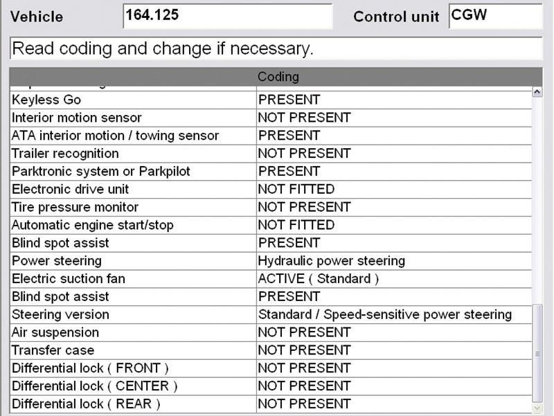
(1) At the Quick Test screen, choose CGW
(2) Control Unit Adaptations
(3) Read coding and change if necessary
(4) Vehicle-specific data
Scroll though the entire open window and notice all of the equipment with messages attached under the Coding column. Blind Spot Assist and Xenon headlamps are PRESENT. With XENTRY, the entire CGW controller configuration can be viewed along with a list of installed equipment. Requesting a print offers detailed information.
With a Gateway that has no errors, what do the messages look like? Note that one function of the gateway is to pass information to the intended network(s).
Hint: Go back and notice Automatik-Getriebe (C423)@vorhanden, CAN-C: Blind Spot Monitoring@available with the XENON headlamp system. Keep in mind other non-communicating controllers.
Using WIS to go even deeper
Using the Workshop Information System with XENTRY offers the precise information via VIN and will aid in further diagnosis, functions, tests, and diagrams with proper re-fitment illustrations. WIS and XENTRY are “joined at the “hip.â€
Two networks are of interest:
- CAN C = Engine CAN and known as “chassis CAN.â€
- CAN B = Interior CAN and known as†body CAN.â€
A good place to start especially if you’re new to XENTRY, is to press F6 (Help) and go to Networking topology (CAN, telematics) CAN networking Interior compartment. Look for and view the Arrangement diagram and x30/19 Voltage distributor (CAN C) Right Front.
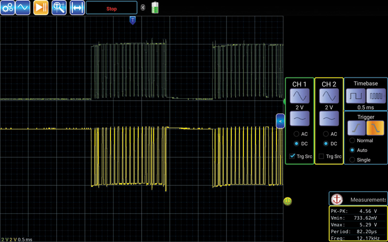
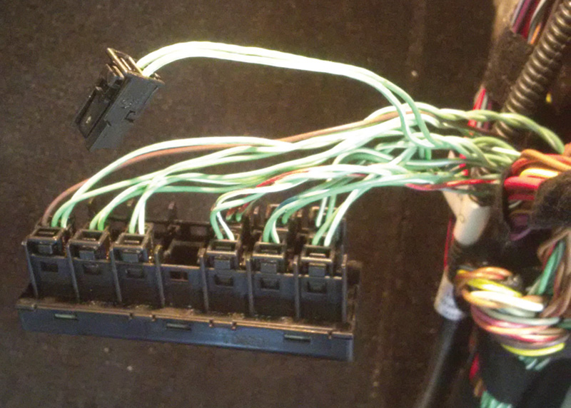
For the following test, gather the correct schematics and follow the wire positions for CAN B and CAN C. The accompanying image is expected with KOEO while connected between the CGW and the CAN B connector station.
Leave the oscilloscope connected ,cycle the ignition key once, return to XENTRY, and reattach it to the DLC. Perform a Quick Scan and there will be faults generated from all previous tests. Clear all fault recordings generated by XENTRY. Follow the clear-faults procedure according to the prompts on the screen. XENTRY will now produce an updated list of controllers and any faults that have returned. Save this updated scan and read it in its entirety. Search for the differences and communication status for all installed controllers.
This case produced five printed pages with no errors. With the information provided earlier, the “bad actor†is now evident.
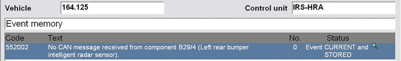
The resulting scan found two controllers missing:
- IRS-HRA – Outer right rear intelligent radar sensor system
- IRS-HLA – Outer left rear intelligent radar sensor system
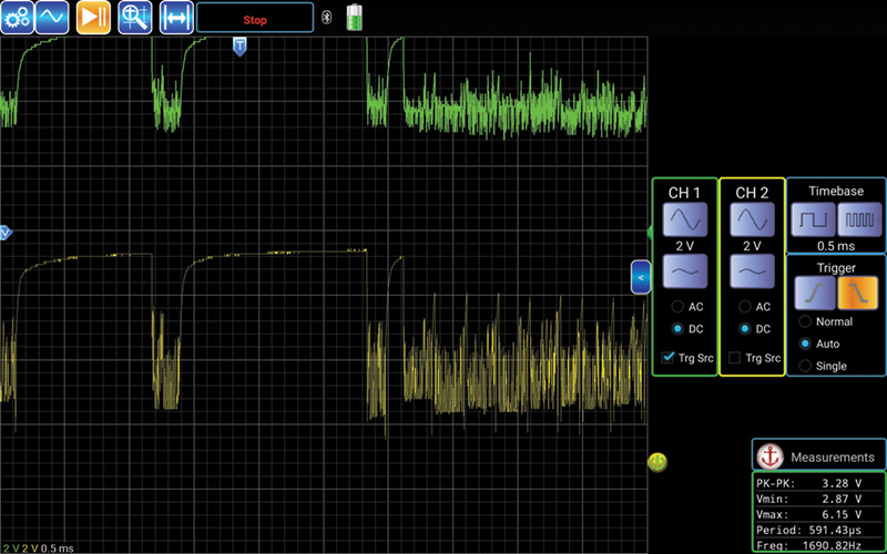
Test this again with the oscilloscope by reconnecting the harness to the station. The oscilloscope will react immediately and chances are that the customer’s complaints returned.
The test can be proved with some accuracy with XENTRY identifying non-communicating controllers in the network.
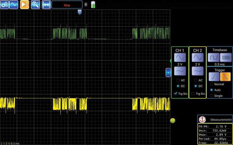
Disconnect the harness at the station again and look for a normal oscilloscope pattern. Inspect both Blind Spot Monitoring modules and harness connections of the vehicle.
Choose either left or right, but disconnect one side and confirm with the oscilloscope. If the correct/defective module is disconnected, the oscilloscope reading the CAN pattern returns to normal and XENTRY will produce a final outcome. On the last Quick Scan, one controller is not recognized because it has been disconnected, but the network is back to normal.
There will be a warning within the instrument cluster that Blind Spot Monitoring will not be available. All other functions should be back to normal with no warning chimes, proper wiper functions, and the Direct Select operating normally.
Well-trained technicians who repair Mercedes-Benz vehicles using the XENTRY system with WIS have a clear advantage and have access to critical programming and adaptations.
Download PDF 〉


0 Comments