
Ockham’s razor: This principle can be interpreted as stating, “Among competing hypotheses, the one with the fewest assumptions should be selected.â€
If there is an assumption and you believe a control module “wakes up†and/or remains awake for no reason, this article may help the learning technician. If there is a suspect control module and misbehaving/depleting battery voltage, there is another option if there’s access to a J2534 device.
Another Tool In Your Tool Box
When measuring a parasitic draw, the modern technician would use an amp clamp on the ground side to accurately measure total current draw. The method is to measure the current draw and investigate if the actual measured value is within manufacturer specifications.
Another test measurement is using a multi-meter to measure the voltage across the fuses. It is possible to find the one specific circuit that is active. Part of the challenge occurs when that one circuit has multiple functions.
| Tools needed |
| DrewTech CarDAQ Plus w/WiFi & a scan tool of your choice |
| 90 amp clean and stable power supply |
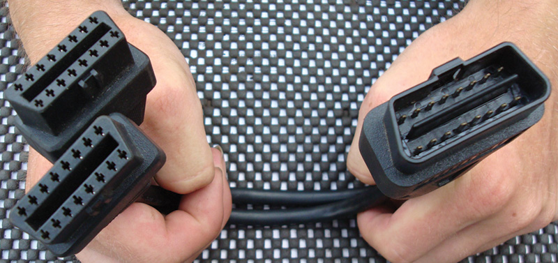
| Split DLC “Y†cable |
| DLC breakout box and a few salvaged DLC connections |
| 60 ohm resistor or decade box |
| Screen capturing software |
Another part of the challenge is when the electrical system is disturbed by disconnecting the power supply via battery or circuit protection. At times, disturbing that connection may re-start or re-boot that one controller or device. And in some cases, that re-start/re-boot may temporarily fix the problem.
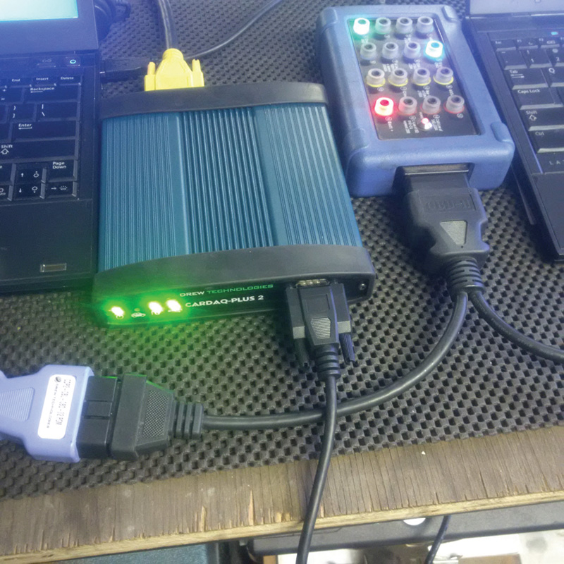
Note: There are many other examples of network analysis tools, but if the CarDAQ Plus, Plus 2, ISO CAN or MFC Pro are available, put them to use besides on-line programming.
Experiences
This particular article shows the CarDAQ Plus and also the CarDAQ Plus 2. This tool has multiple purposes — Flash, Diagnostics, and CAN analysis.
The interest is to measure CAN activity with a great tool that offers well-made analysis software that can be acquired from Drew Technologies.
The oscilloscope will indicate activity of any type but the interest is, in the simplest terms, “who is it.â€
Method To Test 1
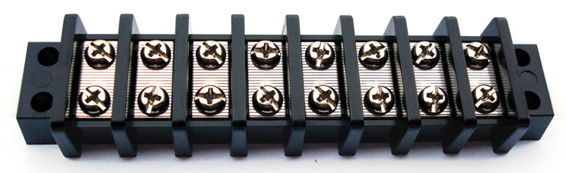
The first of many tests can be performed on the test bench. A series of strip connector blocks can be used to create a stable, safe and identifiable system to connect multiple salvaged controllers into a DIY network. Two blocks can be used and fixed together to create one long connection. The connections can be identified and tagged so that connections such as B+, B-, K-Line, CAN High, CAN Low, and anything else required, are easily legible.
You can attach a salvaged DLC and also connect a clean 12 volt power supply. This experiment has been performed many times for many reasons and with used VW Group controllers (VAG). What the network is comprised of:
| An Audi A4 (RB4) instrument cluster | (vintage 2002) |
| A VW Passat 2.8L engine controller | (vintage 2002) |
| A Porsche Cayenne air bag controller | (vintage 2006) |
| A VW Jetta comfort control module | (vintage 2003) |
This makes a Frankenstein network that can be connected to various scan tools. Proof is the connection to the DLC and verified with the Ross-Tech VCDS with an OBD II tool.
Note: This is an active bench test and everything is hard wired with an on/off switch at the B+ supply, but also at each controller. A real world test is to measure network activity and with the vehicle prepared in a different fashion.
Method To Test 2
Requirements are: a controller, connections, and the schematics that fit the controllers for bench testing. With the controller connections and proper fitting “eye†connections to the connector block, an active and safe network is operating.
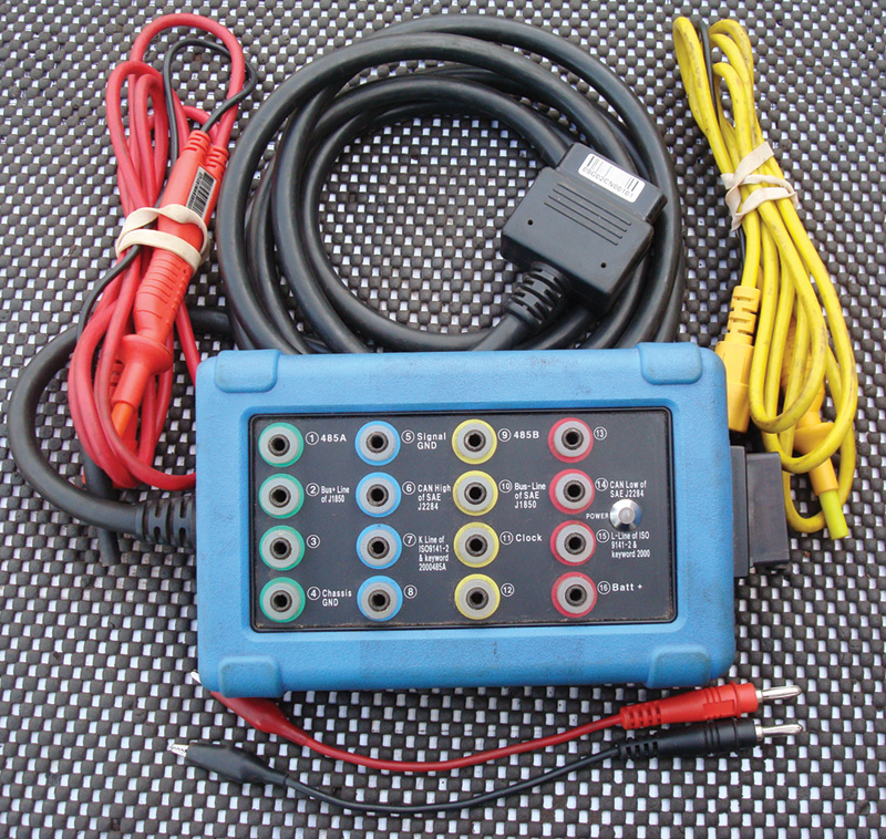
With a little thought, nearly anything from any make, model, or year can be active. This choice is VW Group (VAG) controllers. A DLC breakout box can also be used to help identify the active connection via diagnosis. That connection can be CAN, “K,†or “L†line, depending on the controller. The DLC box also offers a connection for an oscilloscope.
Connect the breakout box cable to the DLC of the Frankenstein network and scan tool to the DLC box. With an active network, there will be “chatter†on the affected communications circuit when it’s alive and/or communicating. With the added BNC cables into the active port of the DLC box, measure the “chatter†with an oscilloscope. Simple diagnostics are accomplished within this configuration.
Method To Test 3
For this experiment, be aware that you can accomplish this task with one laptop and open multiple screens to view the data with multiple USB ports for tool connectivity. That would mean multiple windows that display the oscilloscope (if desired), a scan tool if PC based, with the J2534 analysis software. Using two laptops is identical for these tests, one to diagnose and another to “listen†or sniff network packets. The choice is yours. Note that many laptops have only one USB port and choose that setup for speed, image recordings, and screen captures on both machines.
Note: The CarDAQ Plus also has a LAN port, and that port can be used for connectivity to the PC. A LAN port has advantages such as SPEED!
The CarDAQ Plus 2 is USB connected. Newer versions of the Plus 2 will connect via Bluetooth.
Preparation
With or without the Frankenstein network, make sure a stable and clean power supply is applied. Ensure the scan tool can communicate with the vehicle systems with one connection at the DLC splitter cable. The other (identical) end is attached to the J2534 device.
- Using the other laptop (if available), make sure the correct CarDAQ J2534 software and drivers are installed and operating.
- Acquire the J2534-1 API version 1.07 or higher from Drew Technologies and install the application.
- Know exactly the DLC configuration for the model, which pins are communicating, and what communication protocol the controllers use.
- Adjust the J2534-1 API for the correct J2534 device and communication protocol you’re interested in.
- If this is a real world and non Frankenstein diagnosis, prepare the vehicle in this fashion:
- Any open doors, hood or trunk must be latched.
- A DLC breakout box is a consumer (parasitic load), so be aware.
- The vehicle, in theory, is in sleep mode for a correct measurement.
- The scan tool itself can wake up a network and be a consumer.
- The scan tool is a network, so be aware.
- The key or wireless fob cannot be active with the vehicle.
- Do not set the alarm, just wait for sleep mode.
- If the alarm sets, use the mechanical key to unlock twice to disable.
NOTE: If you want to test a possible CAN controller that is active and awake on the network, a 60 ohm resistor or decade box MUST be attached to CAN High (16) and CAN Low (4). If you’re working on another type of network, i.e.: Ford medium speed CAN, attach to CAN High (3) CAN Low (11).
If that resistor is NOT connected, NO messages will be displayed.
For this test, a decade box was attached to the DLC breakout box and set to 60 ohms.
The resistor is added to eliminate the echo when the CarDAQ Plus (or Plus 2) is “sniffing†for CAN messages. If a scan tool is used to “sniff†test or view CAN messages, the resistor MUST be removed.
Either way, with the scan tool and J2534 device, the application will record an active network with or without a scan tool.
What Can Be Found In The Experiment?
The Porsche Cayenne air bag controller is nearly identical to that in the VW Touareg. The controller uses B+, B-, CAN High and CAN Low, air bags and seat belts can be simulated (but not necessary), and VCDS is able to interrogate that controller and view live data. With the scan tool disconnected, the air bag controller is active in this test because it is directly wired to B+ and B-.
Depending on what you want from this experiment (the interest was the active address the analysis software is listening to), you may find some interesting bits and pieces that should allow a simple perspective of what the CarDAQ J2434 is capable of, instead of just a “flash tool.â€
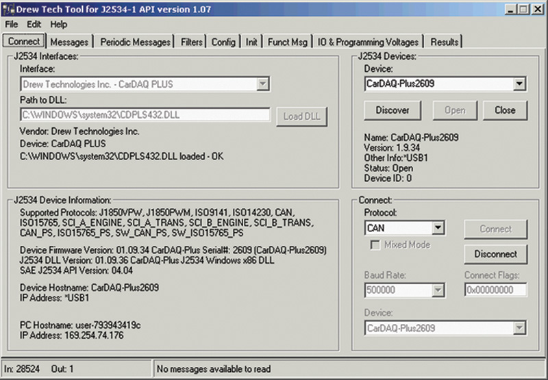
In the correct order
- Interface: Choose CarDaq Plus (in this case)
- Path to DLL: Click Load DLL
- J2534 Devices: Click Open
- Connect Protocol: Choose correct protocol
- Click Connect
The next adjustment is at the Filters tab.
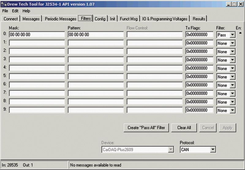
In the correct order
- Click Filters Tab.
- Click Create “Pass All†Filter.
- The protocol was chosen from the primary screen.
- Click Apply when done. The screen should look like this if correct.
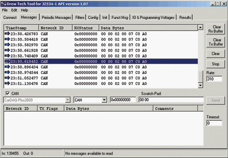
Click the Message Tab.
When the application is started at the Connect tab, the J2534 is to be loaded and the Protocol is chosen. The analyzer is now active. (View Load and Filter Screen images below.)
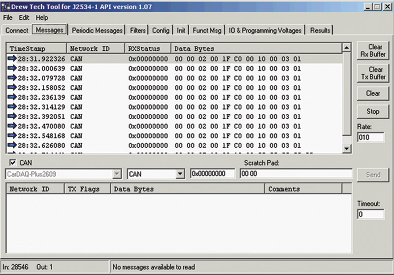
NOTE: The VCDS cable is a CAN Transmitter/Receiver and the J2435 analyzer WILL display data with NO connection to any controller.
Therefore with only a CAN cable connected, the message 1F is repeating.
A network is active and being recorded.
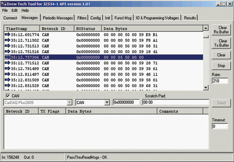
On the Messages tab and if a scan tool is not used with the correct resistor in place, the air bag controller will constantly send data via CAN.
That network address is 05. The scan tool address is 15. Note that!
Increasing the “Rate†will slow the messages for easier viewing. The Start/Stop buttons allow data to be read in the window at a different rate.
When viewing data or starting the read again, click Stop, and clear all (TX and RX). Click Start to look at fresh data.
The Clear/Start/Stop buttons can be used at any time to “flush†data and start the recording at any time.
The Frankenstein network has multiple controllers attached as mentioned earlier. With VCDS connected, the next controller to be interrogated is the instrument cluster. Remember that the 60 ohm resistor has to be removed to measure and record the CAN address when using the scan tool with the J2534 application.
This next image (Instruments Message) is the recording of the Instrument Cluster and that CAN address is 07. The VCDS address to request Instrument Cluster Electronics is address 17. Note this as well.
What Does This All Mean?
Simply put, for relevance and drawing from the earlier paragraph, a network controller that is actively transmitting data because it is awake will produce specific addresses and be recorded via the J2534 application.
How far can the technician go with this knowledge?
The limit is the installed controllers, and if the controllers are active.
This setup is only as complex as the installed network. Depending on year, make, and model, a competent technician should be able to search the available systems with the correct protocol using two methods as a test.
First, complete and save the autoscan.
Second, access a schematic and look at the 16 pin DLC connection and identify which controllers are on which data lines.
Note the installed controllers with the scan tool address and also note the CAN address as described earlier.
This partial scan is from a full CAN vehicle:
| Scan tool address | CAN address 1F |
| 01-Engine | CAN address 01 |
| 02-Auto trans | CAN address |
| 03-ABS brakes | CAN address |
| 04-Steering angle | CAN address |
| 08-Auto HVAC | CAN address |
| 09-Cent. elect. | CAN address |
| 15-Air bags | CAN address 05 |
| 16-Steering wheel | CAN address |
| 17-Instruments | CAN address 07 |
| 19-CAN gateway | CAN address |
| 22-AWD | CAN address |
| 25-Immobilizer | CAN address |
| 42-Door elect, driver | CAN address |
| 44-Steering assist | CAN address |
| 46-Central conv. | CAN address |
| 52-Door elect, pass. | CAN address |
| 53-Parking brake | CAN address |
| 56-Radio | CAN address |
| 62-Door, rear left | CAN address |
| 72-Door, rear right | CAN address |
There are 101 entries with all known VW/Audi/Bentley/Lamborghini addresses (most shared) and not including the LT3 (Mercedes VW).
The homework is to fill in an Excel spread sheet with the needed addresses when “pinging†or accessing each controller. The J2534 application is more than happy to write messages on the screen until all the addresses are investigated.
What Can Be Done With It?
Think about the possibilities if a complete record was created and saved for all VAG addresses. Think of the possibilities of recording other manufacturers’ addresses. If the controller is awake and sending data to the DLC, wouldn’t that be an “epiphany†when applying the Ockham’s razor principle and the KISS factor all at once?
The illustration and guide is the most common VW setup known at the moment. Other manufacturers will have slight variations and NOT all communications are CAN.
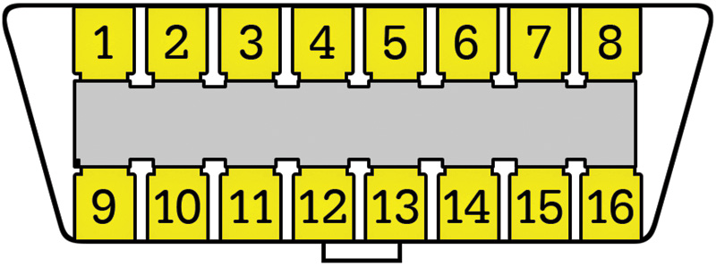
| Pin | Signal | Description |
| 2 | J1850 Bus+ | |
| 3 | Not in use | |
| 4 | CGND | Chassis ground |
| 5 | SGND | Signal ground |
| 6 | CAN High | J-2284 |
| 7 | K-LINE | (ISO 9141-2 and ISO/DIS 14230-4) |
| 10 | J1850 Bus- | |
| 11 | Not in use | |
| 14 | CAN Low | J-2284 |
| 15 | ISO 9141-2 L-LINE | (ISO 9141-2 & ISO/DIS 14230-4) |
| 16 | +12v | Battery power |
A Little Deeper and Outside The Box
So what if a more direct approach is needed, meaning a “direct to the controller harness†connection via back probe. It would be a very good test because the approach is identical to using the vehicle DLC.
What Is The Approach?
Some communications are still “in front of the DLC†and other modern vehicles are behind the gateway.
All that’s needed is a sub harness connected to the DLC connection of the J2534. You can use a scavenged DLC with all 16 pins populated. The DLC may have a twisted pair NOT connected to pins 6 and 14 of the vehicle DLC. That twisted pair may have the 60 ohm resistor attached close to the DLC and high quality back probes attached to a meter length of the twisted pair.
Now bring that connection anywhere in the vehicle and test the theory directly. Remember, the J2534 device must have B+ at PIN 16 and B- at both PINs 4 and 5.
Why All The Trouble?
So that the vehicle is left completely undisturbed, in its original configuration and the fault theoretically still active.
Download PDF


0 Comments