
This safety essential is changing all the time. Make sure you understand newer systems and how they’re integrated with other features.
 was the first production passenger car in the world with ABS.")
The 1978 S-Class (model series 116) was the first production passenger car in the world with ABS.
It’s been exactly 40 years since Mercedes-Benz introduced the first commercially-viable antilock braking system to the automotive world. Although no hard statistics exist, presumably it’s saved many thousands of lives, and many more serious injuries. On top of that, it set the stage for ESP (Electronic Stability Program), which has kept humankind from more grief. Of less importance to life and limb, there’s the benefit of traction control, in which the spinning wheel is automatically braked so torque is sent through the differential to the other side to help keep you from getting stuck in snow or mud. And there are yet more advantages to having ABS components aboard, as we’ll see.

While this 1978 ABS control unit doesn’t look all that different from a modern one, it’s way less sophisticated.
Thanks to digital technology, the electronic components of ABS have always been capable of recording, comparing, evaluating, and transforming sensor data into governor pulses for the brakes’ solenoid valves within milliseconds. Since 1984, ABS has been standard equipment on all Mercedes-Benz passenger cars. Ten years after the introduction, as many as a million Mercedes-Benz cars with ABS were being operated on the roads throughout the world.
As you’d expect, ABS development hasn’t stood still, and many improvements have been made, especially through the collaboration of Mercedes-Benz and Robert Bosch. Here, we’ll explain what the latest advances in this technology mean to you, the ISP (Independent Service Provider).
The innovations continue
The complete control system is becoming smaller, more efficient, and more reliable. The initial, typical pulsating of the brake pedal, indicating ABS activation, has largely been eliminated today. However, the system not only safely brakes the vehicle while maintaining perfect steering, it also serves as the basis and pulse generator for the acceleration skid control (ASR) system, the Electronic Stability Program (ESP), the Brake Assist and of course also for the electro-hydraulic brake system, Sensotronic Brake Control (SBCTM).
In Mercedes-Benz passenger cars, the wheel sensor data also serves other functions such as being processed by the electronically-controlled automatic transmission that adjusts to the driver’s wishes, the navigation computer, DISTRONIC proximity control, the engine and windshield wiper control, the active suspension control (ABC), and 4MATIC. In short, almost everything in the car that is controlled on the basis of speed is using the wheel speed sensor data.
Adaptive braking
When we talk about Mercedes-Benz ABS, we are really talking about a group of integrated systems that all work together to carry out the function of safe, efficient braking. Adaptive braking (ABR) assists the driver in dangerous situations that occur suddenly, so it’s an active safety component. The ESP control unit (N30/4) evaluates data from the following components in order to detect the current driving situation:
- Yaw rate, lateral and longitudinal acceleration sensor
- Wheel speed sensors or axle rpm sensors (all four)
- Steering angle sensor
- Stop lamp switch
The ABR system is made up of the following sub-functions:
- Electronic stability program (ESP)
- Electronic brake force distribution
- Exhaust test/roller dynamometer mode
- Antilock brake system
- Acceleration skid control (ASR), electronic traction system (ETS)
- Brake Assist System (BAS), or BAS Plus
- Trailer stabilization
- Hill start assist
- Various other functions based on model numbers and option codes.
ESP
ESP prevents the vehicle from breaking away when oversteering or understeering. It helps keep the vehicle from deviating from the course intended by the driver. Brake forces are distributed selectively to the individual wheels to correct any deviation. In addition, reduction of the drive torque takes place in order to increase directional stability and road adhesion. The ESP control unit processes the following measurement quantities to determine the vehicle’s behavior:
- Yaw velocity
- Steering wheel angle
- Brake pressure
- Engine torque
- Transmission stage
- Lateral acceleration
Two types of intervention can take place. In the case of oversteer (fishtailing), brake pressure is built up at the outer front wheel. The resulting reduction in lateral force at this wheel generates a yawing moment which counteracts the tendency of the vehicle to rotate inward. Speed decreases as a result of the brake force at the front wheel, which also enhances stability. In the case of understeer, the maximum possible lateral force at the front axle has been exceeded. In other words, the vehicle pushes via the front axle to the outer edge of the curve. The rear inner wheel is braked to generate a torque to help counteract the “plowing.†If the driver presses the accelerator pedal at this time, the drive torque will be reduced first.
SBC brake control

The SBC hydraulic unit
One of the most complex systems involving ABS that you will encounter today is Sensotronic Brake Control (SBC). You will probably only see this on S-Class models, some 212 E-Class models, and a few others, but you should be prepared. The SBC assists the driver in dangerous situations that occur suddenly, thus serving as an active safety component. SBC is an electro-hydraulic brake system that controls the braking requests for each wheel individually via “brake-by-wire.â€
In normal operation, the hydraulic link between brake pedal and the wheel brakes is interrupted by separation valves. In contrast to conventional pre-ABS brakes, electro-hydraulic control is actuated for each type of braking application. This provides some advantages such as improved metering of the required brake pressure, reduction in stopping distances, and improved vehicle safety dynamics.
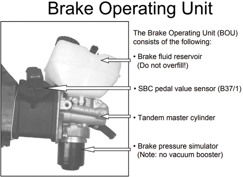
The brake pedal sensor with the master unit
The brake pedal sensor with the master unit
The main components of the SBC system include the SBC hydraulic unit (A7/3) with SBC control unit (A7/3n1), ESP, SPS, and BAS control units (N47/5), the steering angle sensor (N49), the steering column tube module (N80), the yaw rate and lateral acceleration sensor (B24/15), the SBC pedal value sensor (B37/1), and the wheel speed or rpm sensors.
The SBC hydraulic unit is located at the right front of the engine compartment. The SBC control unit is installed on the SBC hydraulic unit. The SBC control unit has these responsibilities:
- Records the driver’s brake application via the SBC pedal value sensor (B37/1) and the front axle pre-pressure sensor (A7/3b1)
- Supplies the ESP with data about how rapidly the driver wishes to brake, and the pre-pressures at the individual wheels via its own CAN (Controller Area Network)
- Supplies the ESP with the vehicle speed signal directly via its own CAN
- Carries out all control functions during normal braking
- Performs all pressure control functions for ABS, ASR, ESP, and BAS control
- Passes on the brake lights signal to the rear SAM control unit with fuse and relay module (N10/2) to directly actuate the brake lights through the CAN (ESP, SPS, and BAS control unit)
The SBC pedal value sensor’s main task is conveying information on the position of the brake pedal to the SBC control unit (at the right front of the engine compartment) via a Hall sensor. The sensor has a mechanism that converts the vertical movement of the brake pedal into a rotary movement for the sensor.
The yaw rate and lateral acceleration sensor is located under the rear SAM control unit. This measures the yaw rate about the vertical axis of the vehicle. The integrated lateral acceleration sensor (AY sensor) measures the lateral acceleration. The integrated longitudinal acceleration sensor reports on the vehicle’s pitching motion. The respective signals from these sensors are read by the ESP, SPS, and BAS control units.

This is the familiar “known-good†wheel speed sensor waveform.
The wheel speed or rpm sensors are located in the front at each steering knuckle, and the left and right rear sensors are mounted on the rear axle wheel carrier. These sensors have not changed much in recent years. They are still the Hall Effect type , which sends data on current wheel speeds to the SBC left and right control units. The newer sensors, however, are more sensitive than they once were, and can detect unsatisfactory installation positions and relay this information to the SBC control unit as well. They still produce the square wave form you are used to seeing when you are performing a diagnostic test to see if you have a faulty sensor.
Here’s where it is imperative to make sure of a clean installation and proper torqueing of new or replacement units in order to avoid complications with your repair. Use a little high-temperature lubricant in the bore of the housing to ensure a proper seating of the new sensor.
The steering column module is located on the steering column, as you would expect. The module is connected to the engine compartment and interior CANs. Communication between the multi-function steering wheel and the steering column tube module takes place via the LIN network. It’s designed to read the sensor switches, buttons, and signals so that the SBC sees all possible driver requests and settings. The steering angle sensor is also integrated into the steering column tube module. The sensor records the current position of the steering wheel and provides the steering column tube module with a voltage signal proportional to the steering lock angle.
Troubleshooting
A common symptom scenario: The customer states that the ABS and Sensotronic Brake Control (SBC) warning lights are on. The instrument cluster displays “Service Brakes Visit Workshop.†First, find out if any other brake work has been performed on the car. If so, here are some possible items to sleuth out:
- If a brake flush was not performed with scan tool direction, a battery charger, and a pressure bleeder, air may have been injected into system. Perform another brake flush correctly.
- If a brake job was performed without using a scan tool, you must connect your scan tool and correctly deactivate and reactivate the brakes. Perform a brake flush.
- Test the Sensotronic Brake Control (SBC) system for leaks and air with the scan tool.
- Check the operation of the pressure sensor and reservoir in SBC with the scan tool-guided tests.
- You may find the scan tool cannot perform guided tests. If so, the SBC unit may have an internal problem such as a damaged diaphragm. Servicing this unit will be a topic for a future StarTuned article, but we will include an important safety note here: Never remove, disassemble, or otherwise tamper with the SBC unit unless you are familiar with the system and the potentially dangerous pressures involved. Always deactivate and depressurize the system according to WIS recommendations before service.
- If the fault will not clear with a good reservoir and no air in the system, the pressure sensor in the unit has failed. Replace the Sensotronic Brake Control (SBC).
The system pressure sensor is part of the hydraulic unit and cannot be replaced separately, whereas the pressure accumulator can be replaced separately. Control units will require programming. If the fault code C249F is also set, do not perform testing. Replace the SBC as the operating time of the unit has been exceeded.

The pinout view of the SBC connector
If you find yourself starting from scratch with your troubleshooting, follow these steps:
- Connect a scan tool and check for Diagnostic Trouble Codes (DTCs) in the ESP and Sensotronic Brake Control (SBC) units.
- With DTCs for hydraulic faults or insufficient pressure supply, inspect for brake fluid leaks or damaged hydraulic lines.
- Perform a brake flush with a scan tool and pressure bleeder. Follow all listed instructions on the scan tool.
- If the pump fails to build pressure, or hydraulic faults continue, replacement of the control unit is needed. Replacing this module will require a factory connector and programmer used with a factory or compatible scan tool. Of course, if you have XENTRY, you’re all set.
- Test powers and grounds to the SBC unit before replacement. See the connector pinout view in
the photo.
Proper bleeding and equipment

This view of an early Robert Bosch ABS hydraulic unit shows why you don’t want dirty old brake fluid in your customers’ cars.
XENTRY or a compatible scan tool with a bleeding system menu is needed for this operation. Also necessary is a battery-maintaining charger to keep the voltage constant, and a power brake bleeder. Here is the procedure from WIS:
- Deactivate SBC brake system using STAR Diagnosis
- Connect the battery charger
- Connect the brake fluid changing equipment (your power bleeder)
- Connect the scan tool
- Raise the vehicle and remove the wheels
- Carry out bleeding operation using STAR Diagnosis menu
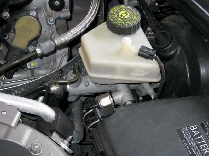
- Check the brake fluid level in the reservoir and correct if necessary

Make sure you have the proper pressure bleeding hook up before you start.
As noted above, trying to service later-model Mercedes-Benz vehicles without the proper equipment and repair information will be futile, and will result in many lost hours of work and damage to your reputation. It should be a given that only Mercedes-Benz approved DOT 4 brake fluid should be used from a clean, sealed container. Remember that brake fluid is hygroscopic and should be replaced on most vehicles every two years. Informing your customers of this need will greatly reduce their chances of future problems in the system.
Download PDF 〉


0 Comments