| Special tools used besides hand tools. |
| 90 amp power supply |
| Ross-Tech VCDS |
| Fluke multi-meter |
| Wiring schematic |
| Additional hand-made harness attachments |
| Camera and lots of patience |
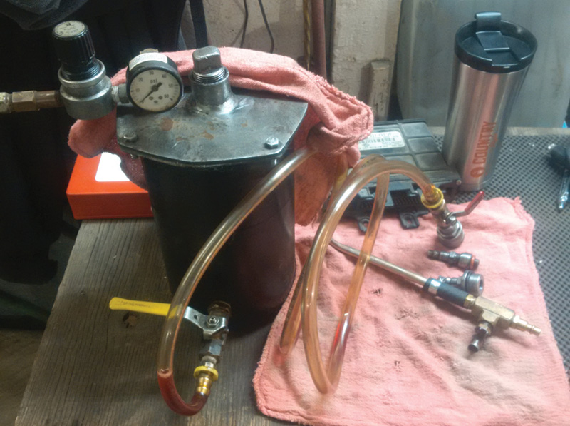
| Force feed transmission oil fill |
Refer to the previous article “The VW 01M Speed Sensors†as additional information. Consider this article as a resource and guide to test speed sensors, but equally an article as to “what can possibly go wrong.†For the learning and uninitiated techs, read the prior version.
On occasion there will be situations when a vehicle owner requests help and/or repair that another repair facility has previously diagnosed. This is one of those times when “a deeper look†leads to repairs beyond the scope of the original diagnosis.
The 65535 error is a “data corruption fault code†and can also be attributed to a hardware malfunction. The list of possible causes is endless but for all intents and purposes, can narrow this fault down to these possibilities in the automotive field:
- Alternator/generator internal malfunction or harness damage.
- Vehicle harness/control unit malfunctions such as B+ or B- connections.
- Voltage spikes from vehicle boosting, reverse polarity, or stray secondary ignition voltage.
Caution: Test/repair that assumption before installing any control units.
The 65535 error in most cases will never delete and if that fault was previously recorded, will return quickly if deleted. In this specific situation, the 65535 error will also mask other errors that would not be generally recorded. Consider 65535 as a fatal controller fault and requiring replacement. In some and not all cases “Internal Control Module Memory Error†may not even record any errors; therefore consider 65535 as one of multiple suspects.
Customer complaint: You may encounter a situation where a previous shop diagnosed the 65535 error but the owner noticed the transmission not shifting correctly and stuck in a higher gear when driving their Beetle.
Have a look first before any assumptions
Scan and save the entire network as a primary baseline. Delete all faults and set basic settings for throttle. Measure and test the alternator output and perform an AC ripple test.
Road test if desired but contemplate the 65535 issues as described.
Give the customer the “what if†because of the 65535 issues.
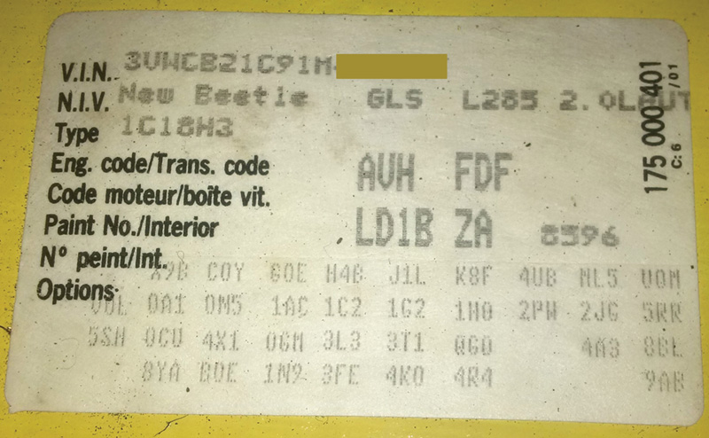
Determine the correct model, transmission code and sales code with the PR tag. The tag is found the trunk and a copy is in the maintenance manual.
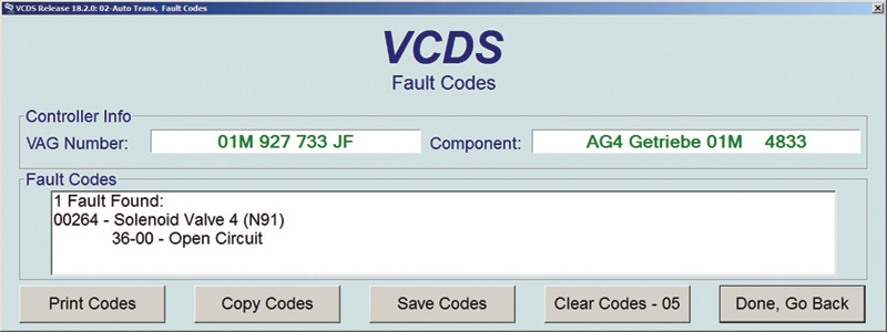
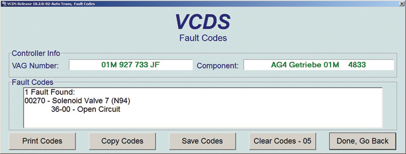
Identify the vehicle and look at the TCM data within the scan (next page):
| Address 02: Auto Trans | Labels: User\01M-927-733.lbl |
| Part No: 01M 927 733 JF | |
| Component: AG4 Getriebe 01M 4833 | |
| Coding: 00000 | |
| Shop #: WSC 00000 | |
| VCID: 7DFA6B3E7785D9ADDE-0958 | |
2 Faults Found:
| 00300 – Transmission Fluid Temp. Sensor (G93) |
| 34-00 – No Elaboration Available |
| 65535 – Internal Control Module Memory Error |
| 00-00 – What else might you find? |
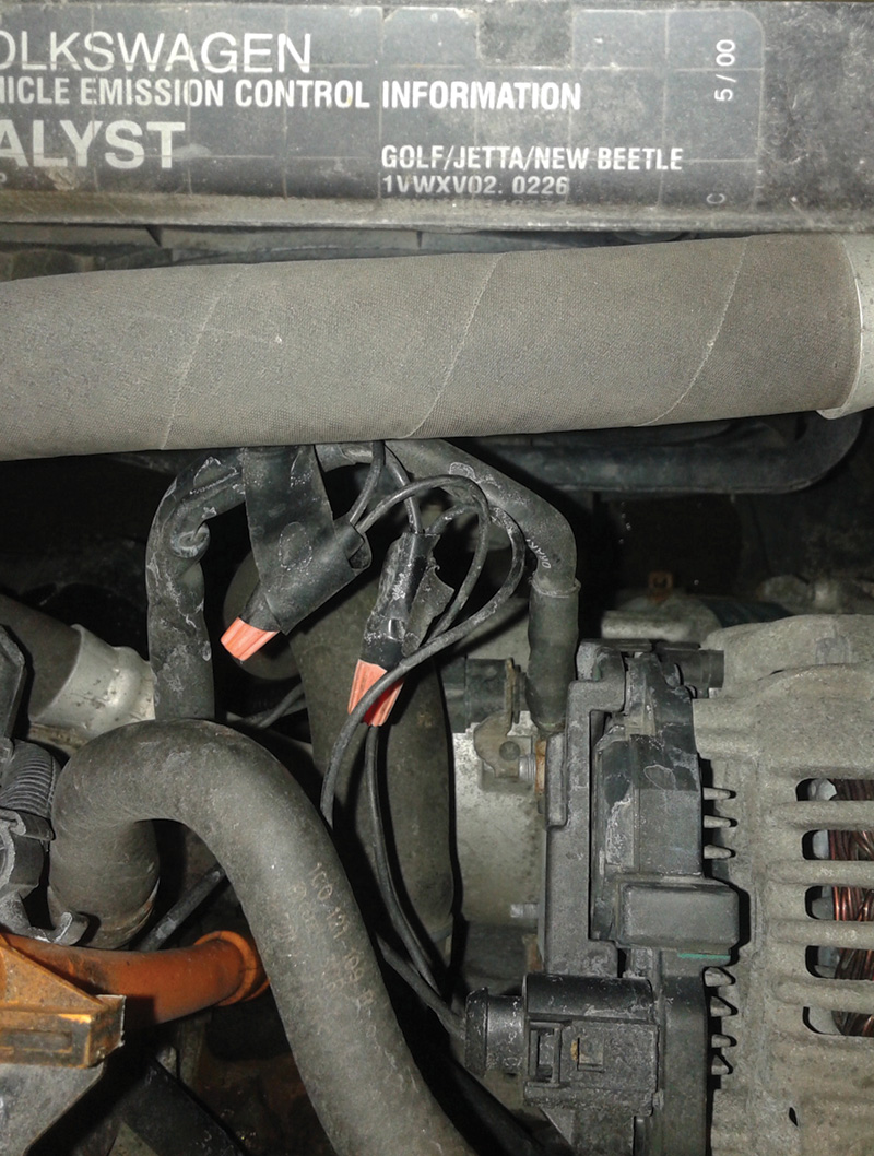
You may find indications of previous sub-standard repair. For instance, here Marette connections were never used to attach the harness to the voltage regulator. The possibility of the wires connected to the incorrect positions was 50-50. The correct repair is performed by using “crimp and shrink†connectors.
The battery, alternator and regulator tests typically prove within specifications. The final test is for a parasitic draw and is also usually within specification.
The next step
The 65535 error will not offer proper/correct/valued data during a road test and the possibility of “limp mode†can also be quite high.
A replacement TCM (Transmission Control Module) is required to achieve any form of proper diagnosis.
Cleaning of the inner plenum is vital only because of the potential for rodents making a nesting bed. So replace the cabin filter in these cases at all times because of bacteria and other bodily fluids.
On to the road test.
Prepare the scan tool to either record or have another technician drive the vehicle and get the transmission to shift in city and highway driving. Attempt to look at TCM and ECM faults during the road test and record all faults. In this case you may note TCM fault 00264 “solenoid 4 open circuit,†and fnote that the transmission does not shift correctly. This fault will delete with the TCM temperature far cooler than driving temperature. Another road test may produce the same fault. The hotter the transmission fluid, the longer the open circuit fault will remain.
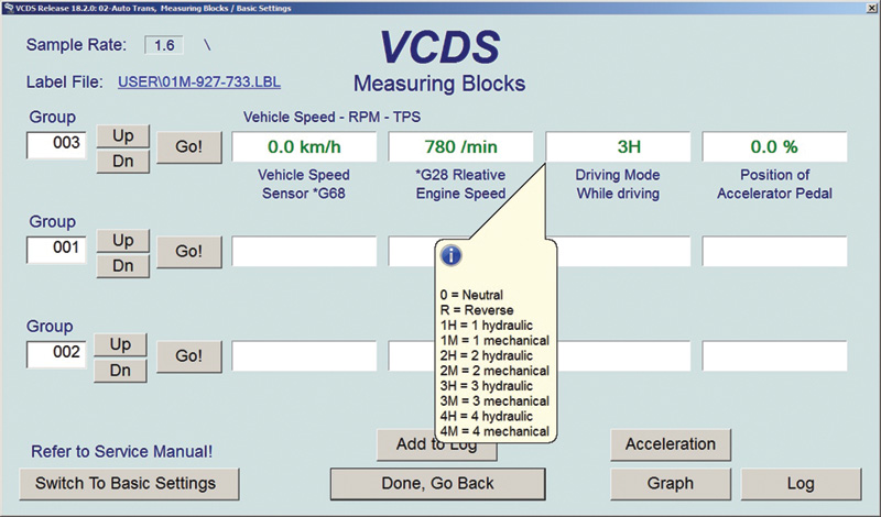
Is there another test? To test limp mode with VCDS and stopped safely, look at the next image. Notice the relationship of where the transmission will begin its driving range.
At 0.0 mi/hr, idle rpm and the Driving Mode in 3H with NO throttle applied, is definitely Limp Mode. Apply this to similar transmissions.
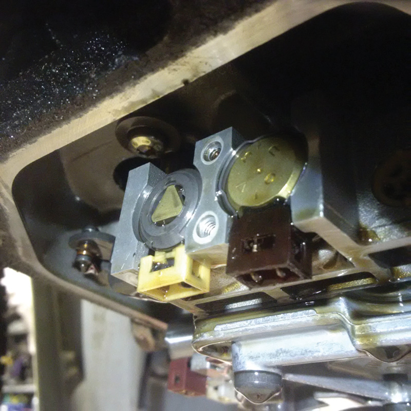
Another test can be accomplished by measuring the solenoid harness on top of the transmission case. Solenoid 4 measures open circuit when hot. Use this image with a schematic to measure each solenoid. Refer to the 01M Speed Sensor article as well.
Check Solenoid 4 at pins 1 and 6. Specification: 4.5 to 5.1 ohms.
Since 65535 errors can mask other errors, a working TCM is the only option to move forward. In this specific situation, the working TCM provides one more piece to the complaint of “not shifting†correctly at times.
Note: Any vehicle of this vintage and with many miles should be suspect to oil, harness, and solenoid degradation.
A replacement solenoid pack, harness kit, with gasket and filter is recommended in this case.
Onward and upward!
The harness connections to the solenoids will self destruct with plastic particles jammed within the solenoid attachment. Therefore a new kit supplied includes:
- Filter
- Solenoid kit (7 solenoids in total)
- Harness
- Gasket
Not so fast!
Solenoids 4 and 6 are measured at 4.5 to 5.1 ohms.
Solenoids 1, 2, 3, 5 and 7 are measured at 55 to 65 ohms.
Paying attention now?
The transmission cooler requires removal/lifting off the portion of the hidden harness. Four seals are required to remount the cooler.
Draining and keeping clean.
On this type of system, the drain plug can be removed (replace the gasket) and the plastic spill port is removed as well. Generally, measuring the volume of oil is a good idea and saved for later inspection with
the customer.
If the decision is to remove the valve body, remember to set the manual valve. If the decision is to replace the solenoids in-vehicle, either way make sure there are photo images and place the correct valve in the correct bore.
Install the new harness and route it correctly, install the transmission cooler with new seals and finish by installing the oil pan with a new seal.
Thread the oil spill port gently and attach the plug. The oil fill tube can be gently unlocked for access to fill the transmission.
That is why the fluid is measured; the correct volume can be added quickly.
Proper filling is with VCDS and measuring the fluid temperature at 95 degrees F (35 degrees C) maximum (check your specs) while the engine is running and drain plug removed. When the fluid spills/drips from the open port, the level is correct. Insert the plug. Simple enough? Not quite!
What if the car is still on the hoist and solenoid 7 has an open circuit?
Back to step one
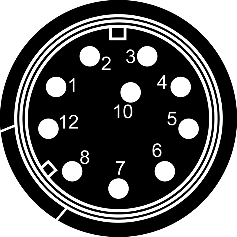
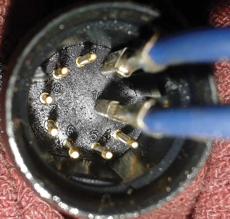
| Pin 1 = B+ supply to solenoids 1, 2, 3, 4, 5, 7 and Temperature Sensor |
| Pin 2 = B+ supply to solenoid 6 |
| Pin 3 = B- signal to solenoid 1 |
| Pin 4 = B- signal to solenoid 2 |
| Pin 5 = B- signal to solenoid 3 |
| Pin 6 = B- signal to solenoid 4 |
| Pin 7 = B- signal to solenoid 5 |
| Pin 8 = B- signal to solenoid 6 |
| Pin 10 = B- signal to solenoid 7 |
| Pin 12 = Temperature signal return |
Pins 1 and 10 are measured and the value is open circuit, so a replacement harness and solenoid are the fix here.
The tests and learning lesson – for the uninitiated.
Measure twice, cut once!
- The drain plug and spill port is removed, capturing the fluid.
- Pan removed and harness disconnected at solenoid 7.
- Measured from the transmission end harness to the solenoid harness.
- Found an open circuit in new harness.
- Solenoid 7 is the one in white.
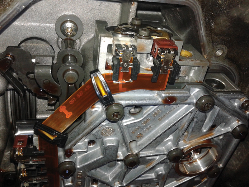
Note the temperature sensor attached to the foil strip below solenoid 7.
Double check
Measure the replacement harness and ensure connectivity by using a snug fitting pair of wires (female) and correctly sized male end to the solenoid ends of replacement harness.
Using the TCM Connection image and PIN location description, the harness and solenoids can be measured in-vehicle to determine if all the solenoids are connected and the harness is intact. Follow the next series of steps to double check the replacement components before assembly.
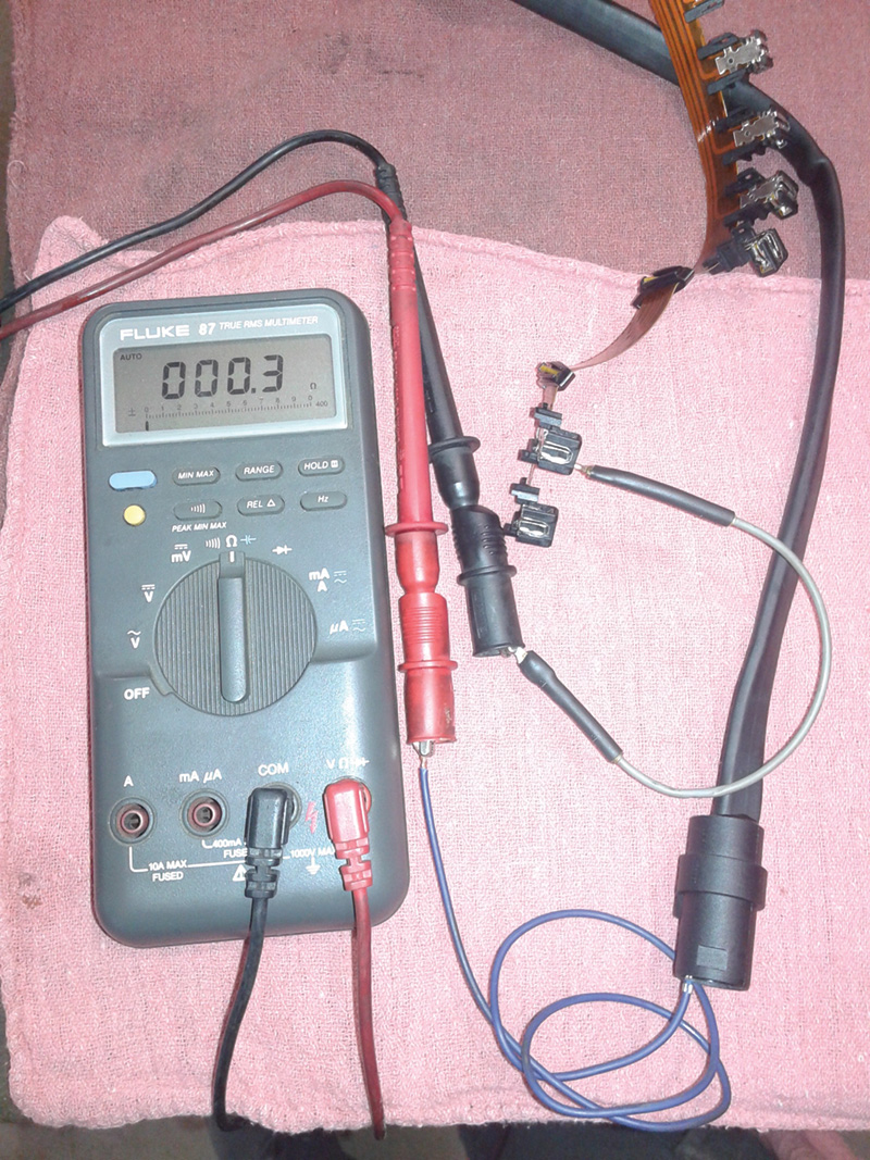
Using a high quality multi-meter, measure the entire harness according to the wiring schematic to confirm that the replacement harness passes the continuity test.
Since the two blue female wires fit the round pins, the next test is after the assembly onto the valve body. The test can be done in-vehicle using the same pin layout described earlier. Measure with an ohmmeter or with 12 volts.
Note: These are 12 volt solenoids and can be tested with a voltage supply to the correct B+ and B- connections. Audible clicking should be heard by applying power or ground intermittently to the individual solenoids.
Hint: By increasing or decreasing resistance with a decade box, the TCM can be fooled into different temperature variances at pins 12 and 2. That test would prove out a defective transmission oil temperature sensor within the transmission strip harness.
Replacement harness under test with made up harness to fit both ends.
Install in the reverse order and ensure the harness is tight and routed correctly. Refill the transmission again and, with VCDS, setting the correct oil level, against transmission oil temperature.
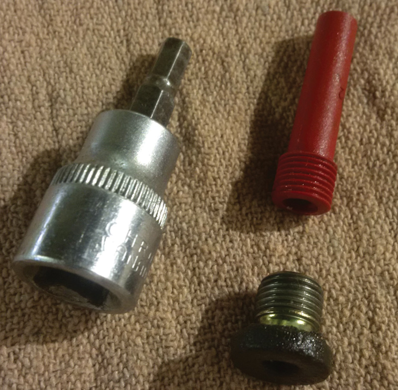
How many ways to fill transmissions of this style? Gravity feed tends to be a bit slow, a hand pump is too much work but this one is air regulated with two ball valves.
That will also mean that, with the correct adapter and coupler, different styles of fill ports can be fitted to one basic tool. 5 psi is enough pressure and the ball valves control the volume of fluid when force feeding through small ports.
The control of each ball valve also allows the fill side to remain closed but the spill side open to watch for the drip at the temperature with VCDS.
Download PDF


0 Comments