
Part 1 of the DoIP discussion introduced what it is and what it stands for. Part 1 also mentions a few names of corporations that are in involved in the creation and deployment of the communication structure. Included are a few known tools and more will be added only because of what is current on the market today.
Throughout this series many more industry names will be added in relation to the structure, deployment and what it means for the vehicle owner with the repair facilities that need to filter through this technology.
Here’s a mouthful while having breakfast.
DoIP serves as a transport protocol standard for Unified Diagnostic Services (UDS ISO 14229-1). UDS is located on OSI layer 7, the application layer. Diagnostics over Internet Protocol runs over the TCP/IP protocol stack. TCP/UDP on OSI layer 4 is used as the transport protocol. IP serves as a switching protocol on OSI layer 3. Ethernet is the protocol used on the data link layer on OSI layer 2. The physical medium is a 100BASE-TX twisted-pair copper cable on OSI layer 1.
UDS is a diagnostic communication protocol within the ECU environment. This environment is integrated within the entire range of automotive electronics (ISO 14229) that is specified. The specification originated from ISO 14230-3 (KWP2000 ) and ISO 15765 (Diagnostic Communication over Controller Area Network (DoCAN). The term Unified means that this communication protocol is used in almost all new developments of vehicle manufacturers and is not a company-specific standard.
CAN (Controller Area Network) is a dominant and well designed/robust vehicle data-bus customized network. The CAN data-bus interconnects onboard vehicle microcontrollers with multiple devices to communicate with each other. The software and hardware combinations will transfer data without a host computer. CAN is a message-based protocol and designed for multiplex messaging via a twisted pair within the vehicle network.
DoIP will access the Ethernet structure according to an individual IP address. Because of the speed of the Ethernet system and sheer volume of data handling, systems such as Steering/Braking/Audio/Video Bridging and related Driver Assist Systems over Ethernet is necessary and a reality. This will be a reliable step towards future Driver Assistance Systems and semi-autonomous driving.
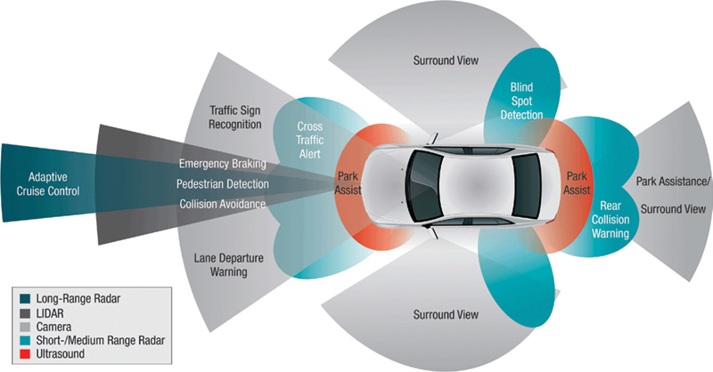
ADAS = Advanced Driver Assistance Systems a/k/a Driver Assistance Systems.
In simple terms; ADAS is a creation that integrates the human and the machine that is tasked to increase general road safety. ADAS is and will be developed far greater into the future. The design is to help avoid road accidents, collisions, fatalities and, with this technology, alert the driver to potential harm. Current and future developments will have programmed strategies to “take control†of the vehicle safety system.
The near future will also include car2car data transmission. There are many good intentions and qualities that
car2car/infrastructure data sharing will incorporate.
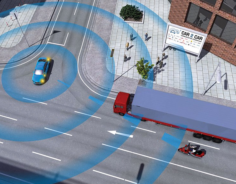
In a future city environment, the traffic and signaling lights will be harmonized within an “information†network. The information gathered will relay real time information about the flow of traffic. Algorithms will allow the optimization of duration/cycles for the traffic and signaling lights. Depending on time of day or night, providing there are no stalled vehicles, double parking, a pedestrian hit or a garbage strike, the positive results include safer/more efficient traffic flow with reduction in stops and energy (carbon based or electric) savings.
On a roadway, highway or non city environment, car2car communications and data sharing can also include warnings of longer distance traffic situations, obstructions, accidents or close proximity warnings. By close proximity, it means that “passing in curve†may NOT be such a good idea if the opposing drivers don’t have a clear view of each other but relays their approximate distance and speed relative to each other.
You want to fix what?
Many questions will arise when these modern vehicles arrive in the repair facility. One very important question will be the “level†of how the scan tool will perform. In general terms, the scan tools we use today have functions that help the modern technician perform diagnostic tests, measure values and record data very close to factory scan tool. Those common functions include: Read faults, Delete faults, Read live data, Perform basic settings, and Adaptations. With laptop-based or Android/IOS systems, the systems can also record events as a diagnostic aid.
The average scan tool we may normally use today will NOT perform within these modern structures unless added hardware is sourced. The average J2534 tools that we are accustomed to, will NOT perform (or will be very slow to perform) within this modern structure. Diagnosis over IP will be the new standard. Modern and high end J2534 devices will diagnose and or flash over an IP address.
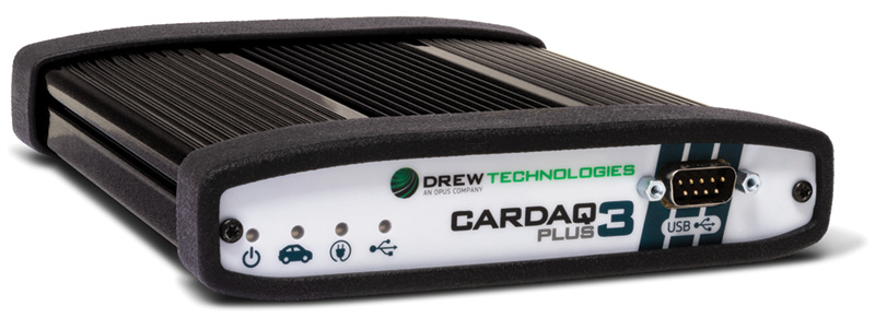
Supporting CAN FD, J2534 v05.00 API, 4 CAN channels and DoIP
Here’s an interesting thought with the automotive Ethernet.
How do we measure this?
How do we know this modern structure/protocol can display all messages via CAN and Ethernet?
Let’s start from the beginning.
There were “blink codes†back in the days and with the “K†line, the simplest tools were the “flavor†of the day that gave controller access to the technician with either a hand-held device or laptop-based equipment.
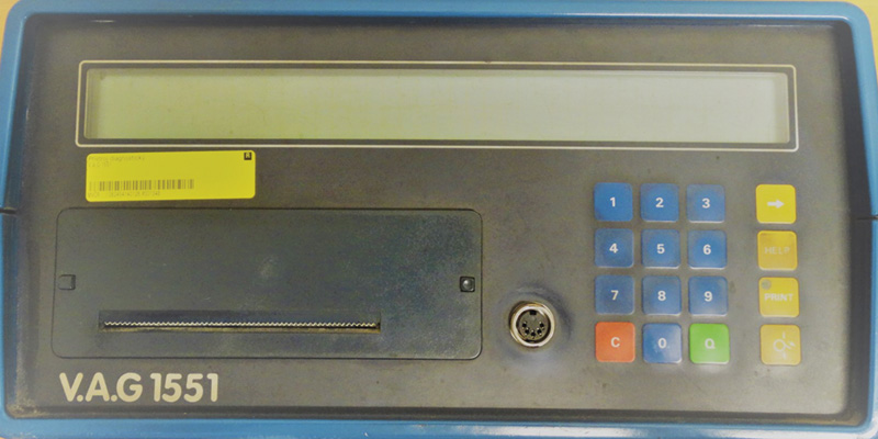
In those days, the VAG1551 wasn’t really considered a “hand-held†but certainly resembled a large brick with a thermal printer. Then there was the VAG1552 and resembled more of a portable version without a printer.
That access was more like a…… “one liner†at 10.4 Kbit/s with bi-directional control. Current standards are K-Line ISO 9141-2 and ISO 14230-4. Operating voltage is 12V.
In later years came the 5051 and 5052 with a detachable dual “K†line module. For its day VAS PC was an advanced diagnostic system running on a Windows platform that can be software upgraded. The system came with a cart, printer, oscilloscope and the dual “K†line module.
The module was designed to access two “K†lines if the communication standard was built into the vehicle. The 5051 and 5052 versions were CAN capable with access to the LIN/MOST structure with data access and bi-directional control. These scan tool versions can also perform flash updates via CD or Ethernet connection within the facility.
The newest generation will be ODIS (Offboard Diagnostic Information System) and is capable of connecting to all modern VW Group vehicles. Unlike previous versions of scan tools, ODIS is capable of wirelessly connecting via Bluetooth or the latest WiFi infrastructure.
Depending on the purchase of equipment and service environment such as independent or dealership, the diagnostic machine will behave quite differently. In a dealership environment, the functions are more sophisticated compared to those available to the independent. In a dealership, and especially during a warranty repair, everything the technician touches or tests, is recorded and sent to the manufacturer. Part of the process is using “Guided Fault Finding†as an aid for the service technician. Guided Fault Finding was created for the technician to follow a path to a successful repair with the ability to perform basic settings and adaptations. Guided Fault finding also interacts when the technician requires schematics, test procedures and access to an oscilloscope. Guided Fault Finding is created by software engineers and is constantly updated in an on-going process.
For the uninitiated, a refresher
CAN was designed and developed to help with the data speed and data transfer to multiple controllers. The design fundamentally reduced the amount of harness and controller connections required to maintain communications between multiple controllers.
No matter the flavor or manufacturer, CAN became, and still is, a standard communications and data transfer protocol. With CAN came LIN, FlexRay, and MOST. The CAN speed range can be 500 Kbit/s or 250 Kbit/s. Depending on the vehicle, either high or medium speed can be used. Depending on the manufacturer/model, both speeds can be used on separate networks.
LIN is a low cost sub network that communicates with and controls slave modules. The Local Interconnect Network (LIN specification 2.2), transfers data at 20 Kbit/s. The LIN network is a simple and inexpensive way of operating sub-modules such as a duty cycle heater motor, mirrors, sun roofs, or a windshield wiper motor. Operating voltage is 12V.
The FlexRay network supports a star topology, linear topology, or hybrid. This fault tolerant network supports high data rates up to 10 Mbit/s.
FlexRay communication is a deterministic standard and will remain operative even if one channel has a defect. Deterministic means that data arrives in a predictable time frame down to the microsecond.
Controllers actively synchronize themselves including the synchronization of data. FlexRay can have two independent channels for fault tolerance. Bus operation is designed on time cycles and divided into two parts. The dynamic part takes control of a node when available and operates similarly to CAN (not requiring determinism). The static part is allocated into slices for individual communication types with reserved slots for deterministic data that arrives at a fixed period.
MOST is a high-speed multimedia network technology. The Media Oriented Systems Transport system is a synchronous data communication protocol to transport audio, video, voice, and data signals. The speed of light in a vacuum is 299,792,458 meters per second, or 186,282 miles per second. The speed on an automotive MOST system depends on the quality/type fiber line and how it’s connected to the controller. Modern MOST 150 standards can produce speeds of 150 Mbit/s. Certainly NOT the speed of light.
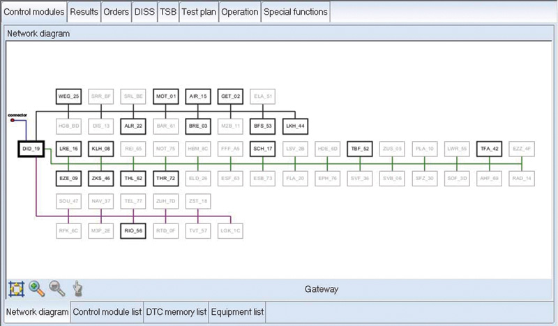
There is an advantage to using this type of equipment because of the network view. Many manufacturers offer these graphical displays to help the technician associate the network structure built within the vehicle being tested.
Kilo, Mega, Giga and more?
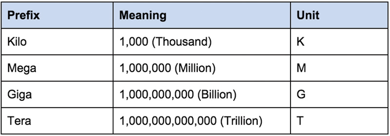
Ethernet is a completely different beast. With the beginnings of 100 Mbit/s towards the 10 Gbit/s speed range, Ethernet will be a common high speed network within the modern automobile. Diagnosis will be far different than the communications standards mentioned earlier.
The earlier image called “Image from ODIS Service Tool†illustrates a common network structure with multiple networks connected to the VW Group models. Not all nodes are connected to this model because they do not exist as the vehicle was built. The image illustrates what is connected with the scan tool as the controllers were found.
VCDS is no different except the complete scan is in view within a text file. Depending on how the modern vehicle is engineered, some controllers may not even be on the list during an interrogation. An example will be a controller that is off-line. Modern vehicles now depend on a Gateway. The Gateway holds all of the information as to what was installed at the factory or how the vehicle was built. If there is a controller that is off-line, one or more controllers will complain about “a communication error.â€
Ethernet and the difference
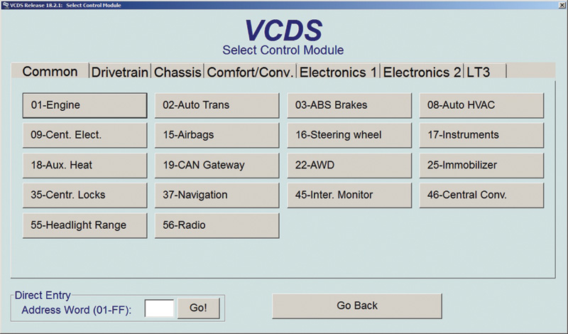
When the familiar controllers are addressed with any VAG style scan tool, the same address will follow the VW and Audi structure. Depending on how modern the vehicle is, diagnosis of the controller is common with either the “K†line or CAN.
Examples will be:
- Address 01 – Engine
- Address 02 – Transmission
- Address 03 – ABS
- Address 05 – Access Start and Authorization
- Address 08 – HVAC
- Address 15 – Airbag
No matter the VW Group model, the controller address will always be the same for the accessed controllers.
The Ethernet difference will be in how the controller is accessed and how data is shared between controllers.
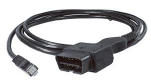
Some manufacturers have opted to using specialized OBD cables with high tech internal MCUs (Micro Control Units) with a LAN cable. The example LAN cable will be attached to a PC or laptop and will require access via a subscription. In that case, a VCI (Vehicle Communication Interface) is not required. Access to any controller on the vehicle will have to be accomplished
on-line and directly with
the manufacturer.
For the moment, VW vehicles will require a VCI.
Part 3 will be rather “enlightening.â€
Download PDF


0 Comments