

Learn the circumstances under which squeeze-type resistance spot welding (STRSW) can be used, along with brief tips for equipment settings and repair procedures.
Nissan allows Squeeze-Type Resistance Spot Welding (STRSW), but only under certain conditions. The part must be made of steel that is 980 mPa (megaPascals, a measure of tensile strength) or lower, you must use the spot welding parameter settings that are spelled out in the vehicle-specific body repair manual (Nissan BRM), and of course, the component must be accessible to your spot welder’s arms (electrodes).
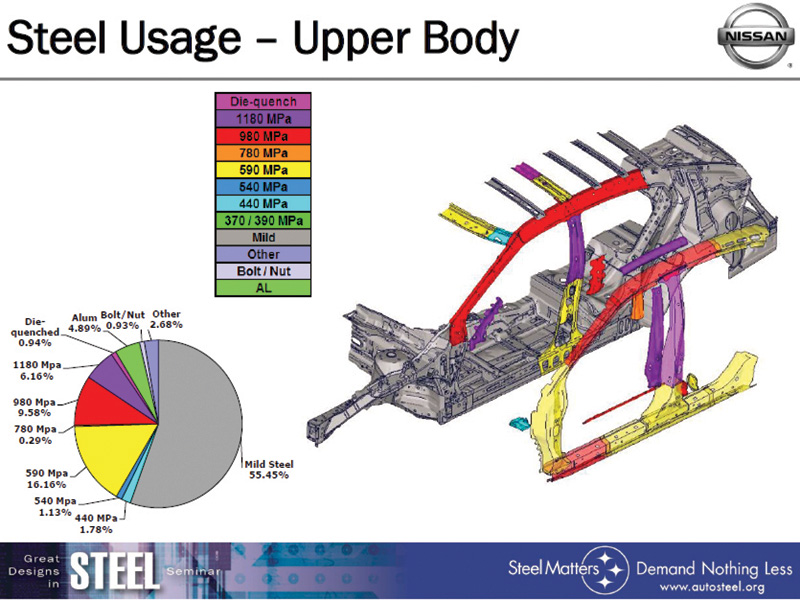
Nissan body repair manuals state explicitly: “Never spot weld components of tensile strength higher than 980 mPa. For this type of ultra-high strength steel, perform plug welding.†Nissan uses Ultra High Strength Steel (UHSS) rated as high as 1,350 mPa, or 1.3 gPa (gigaPascals) on selected components of some vehicle models.
Faster, smarter, better
Resistance spot welding is faster, more cost-efficient and more straightforward to learn than traditional welding methods, but you cannot use it in every situation. It is perfect for joining thin sheet metal because it delivers a lot of energy in fractions of a second and generates only a small Heat Affect Zone (HAZ). The short application time and reduced HAZ allow delivery of enough current to melt the metal, but not so much as to weaken adjacent metal or to warp the panels. Spot welding is not ideal under some other conditions. For example, it generates too much heat for some high-strength steels, it may require multiple welds to replace a single factory spot weld, and you need to create test welds before any repair to make sure that your new joints meet strength requirements.
Current plus pressure and time = permanent joint
Joule’s Law states that the heat produced when an electric current is input to a conductor is equal to the square of the current multiplied by the resistance of the conductor. In other words, the heat generated per second, or the electric power loss (P), equals the current (I) squared, times the resistance (R). This can be expressed as P = I2R. The power (P) is expressed in units of watts, or joules per second, when the current is expressed in amperes and the resistance is expressed in ohms.
Resistance spot welding adds to this heat a precise amount of mechanical pressure to hold the joint stable as the weld is formed, plus a timer to control the length of time allowed for the heating and cooling phases of the welding process. The combination of electric current (heat), mechanical pressure and time management creates a permanent joint.
Multiple sheets of metal overlap while enough current is passed through the mating surfaces to melt the panels together in a tiny area. That area is pressed and held together by the mechanical force of the spot welding gun until the weld nugget cools enough to stabilize its shape. It all happens in a fraction of a second, and the welder moves on to the next area to place a spot weld.
Resistance is complicated, but not futile
Of course, resistance is not just one thing. There is resistance in the welder, and in its cables and electrodes. There is contact resistance between the electrodes and the work surfaces. There is resistance in the metal workpiece, and between each panel in the material stack.
Different material types and thicknesses present differing quantities of resistance. And resistance changes in value as the welding process moves from start to finish.
Resistance spot welding guidelines come in complicated charts that take all of these variables into account. Material thickness (mm), electrode tip diameter (mm), electrode force (kN), welding current (amps), welding time (# of cycles), hold time (# of cycles) are all equipment operating parameters that, when set properly, lead to the creation of a weld nugget in the desired size and strength. A small change in one parameter setting will affect the other parameter values and the outcome of the weld.
Newer spot welding equipment automates much of the decision making once you input the panel thickness. Some even determine the material type and thickness automatically, although you may have to conduct a test weld before starting the actual repair for the equipment to identify the material and panel thickness.
Regardless of whether you use equipment that sets spot weld parameters automatically or you enter parameters manually based on the sheet thickness and other data from a spot welding guidelines chart, it is crucial to understand that different material types, and single sheet thicknesses, dictate the use of diverse equipment parameter settings. Note: when joining sheets of different thicknesses, select parameter settings based on the thinner panel or, if there are three panels, the second narrowest.
Preparation
The first step in the spot welding process is to inspect the panels that are being joined to make sure they are not warped or damaged. Any gap between panels reduces current penetration and allows moisture, air or other contaminants into the weld. Flatten and clamp sheets together before beginning to weld.
The second step is to clean the mating surfaces. Dirt or solid contaminants could prevent full contact between the panels, causing current to flow incompletely or improperly through the joint and weaken the weld. Some debris may contain chemicals that vaporize or off-gas under the heat of the spot welding process, introducing moisture or other contaminants into the weld nugget.
Model-specific spot welding parameter settings
You’ll find one example of Nissan-approved spot welding parameter settings for 980 mPa steel in the 2016 Murano body repair manual. It lists electrode tip diameter, gun pressure, welding current and cycle times for a joint containing up to three plates of 980 mPa or less each.
The parameter settings provided apply to the 2016 Murano only. The BRM states: “Never apply these same conditions to other vehicles.â€
Increase the number of replacement spot welds
In an appreciation of the high power of factory spot welding robots versus the lower capacity of most aftermarket spot guns, Nissan recommends increasing the number of spot weld locations by 20 to 30 percent when doing repairs. Create at least five spot welds for every four factory locations.
Note that the number of spot weld placements recommended in any given Nissan body repair manual may already reflect this recommended 20 to 30 percent increase. Compare the number of spot welds that you remove from the area to the number that the BRM suggests you put in as replacements.
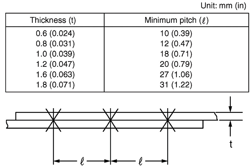
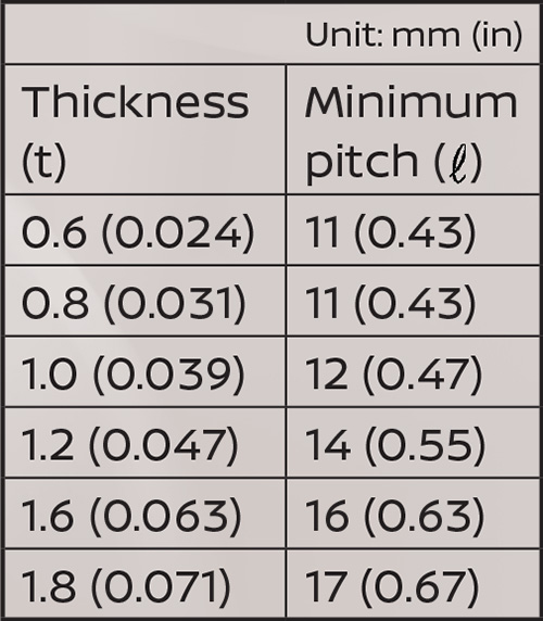
The minimum welding pitch (space between spot weld placements) varies with the thickness of welded panels. Insufficient spacing allows current to shunt (flow) away from the new weld nugget and over into the last weld you created. Diverting power results in weakening of the most recent spot weld. Shunting can occur in all types of metal. The table below shows minimum pitch values for typical automotive panel thicknesses.
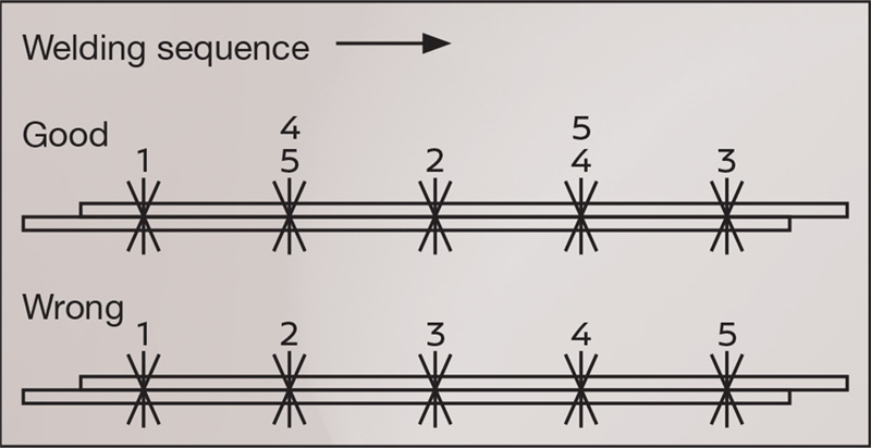
Shunting also occurs if you make sequential spot welds in one direction only. Avoid impairing the weld. Alternate the order of weld placement, and heat will not continually travel in the same direction. Also, if the electrode tips become red-hot, stop and allow the tips to cool.
Electrode arms
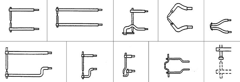
In spot welding, the weld nugget forms at the location where the current passes through the metal. Electrodes made of copper function as conductors to channel current into the work. Electrode attachments for spot welding equipment come in a large variety of shapes and sizes to provide access to a flange or joint that might otherwise be impossible to reach.
Pressurizing
With any debris removed, the electrode arms hold the mating surfaces in close contact with each other for the application of current. Panels in proper contact with each other allow current to flow freely through the joint, helping form the correct weld nugget shape and size. Note that the electrodes do not provide clamping force in the traditional sense. Use C-clamps or other clamping methods to hold the materials together during the welding process.
Energizing
The resistance spot welding equipment applies high current while the panels are squeezed together by the clamping arms. Resistance to the flow of current through the materials generates heat between the electrodes. Different material types and thicknesses require different levels of electrical power, applied for potentially varying amounts of time, to build up enough heat to fuse the metal panels.
For this reason, material thickness is one of the primary parameters used to adjust spot welding equipment settings for a given weld.
Balancing pressure and current
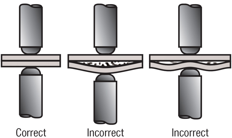
The electrodes also hold pressure at that exact location to ensure weld nugget formation at the desired size and shape. Weld strength deteriorates if current remains constant while pressure varies (or vice versa). Too little welding pressure results in some of the molten material splashing out of the weld area. This excess spatter reduces weld strength.
Too much welding pressure and the current spreads out at the contact point, reducing current density in the target area. Less material is melted and fused, resulting in a smaller, weaker weld nugget.
Similarly, if the pressure remains constant while current varies, the weld nugget size and density will be altered in a potentially unfavorable way. To achieve the ideal nugget size and weld strength, you must stay within the range for each welding parameter as specified in the Nissan body repair manual.
Stay within the specified amount of welding time
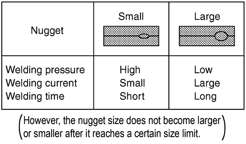
The amount of heat generated in the weld increases with welding time. As heat increases, the weld nugget gets larger, up to a point. Beyond a certain saturation point, instead of nugget size continuing to increase, thermal stress will begin to occur. Some spot welders can sense the nugget temperature and automatically step the current down if needed, without interrupting the welding pulse time.
Apply welding current continuously
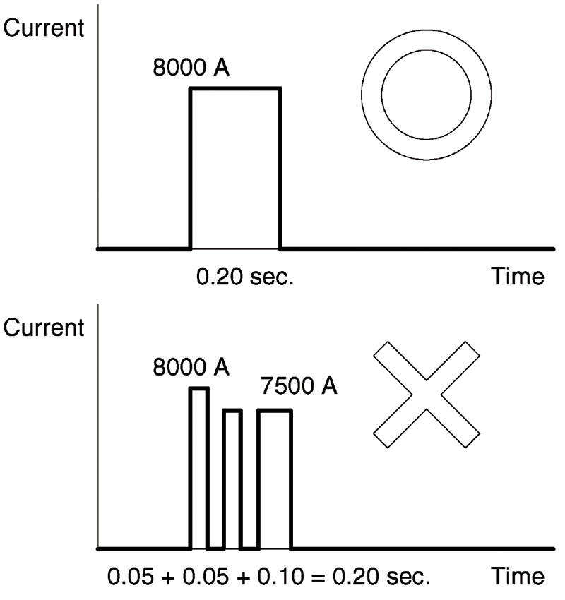
Apply the weld time specified in the repair manual with no interruption. If you pause or divide the current application time, even if the total adds up to the specified amount, the weld nugget will not form properly.
The BRM provides 50 and 60 Hertz (Hz) cycle times to accommodate whichever power type is supplied to your shop.
Hold time is important, too
The spot weld takes a small amount of time to cool down after the current stops flowing. Maintaining pressure during that cool-down time keeps the electrode in contact so it can quickly draw some of the residual heat away from the weld. This helps keep the molten material from spreading out and thinning and weakening the weld nugget.
Minimum panel overlap
Different sheet thicknesses require specific minimum overlap (pitch) widths. Too little overlap results in increased potential strain on one or both panels. This strain reduces long-term weld durability. See the panel overlap chart for minimum lap values by sheet thickness.
Pre-repair weld test
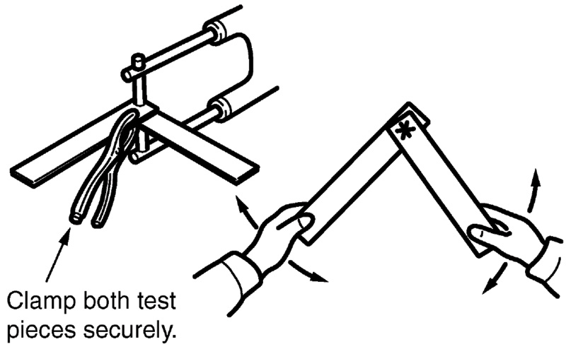
After setting your spot welding parameters, create a test weld before performing the final repair. Cut out a few pieces from the damaged area of the panels, so your test pieces have the same thickness as the new repair. Weld them together, then twist until you break them apart.
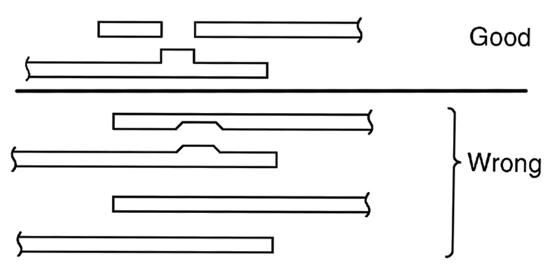
If the repair is good, the entire weld nugget will separate from one side of the joint, leaving a hole. If no hole forms, you need to set different welding parameters. If no spot weld parameter information is available in the Nissan body repair manual, refer to the parameter chart from your welding equipment manufacturer for guidelines appropriate to the material type and sheet thickness of your repair. Remember that Nissan does not permit resistance spot welding of ultra high strength steel rated at higher than 980 mPa tensile strength. Adjust the pressure, welding current, welding time, and other conditions and re-test until you achieve the desired result.
Post-repair weld test
Resistance spot welds should have a shear strength equal to that of the base metal in the joint. When done correctly they are stronger than a rivet or fusion plug weld of the same diameter.
This test is for a hypothetical joint of 0.8 mm to 1 mm (0.12 inch to 0.16 inch) single-panel thickness. Insert a chisel between the panels of your weld and tap it in until the joint separates by 3 mm to 4 mm (0.12 to 0.16 inch). If the spot welds do not break or separate from the panels, the welding was successful. Restore your good weld by tapping the deformed portion back together.
Note that the above specifications are for one sheet thickness for example purposes only. If your actual single panel is less than 0.8 mm (0.12 inch) thick, do not separate the finished joint by more than 1.5 mm to 2 mm (0.059 to 0.079 inches). Opening further may destroy your weld.
Applause, applause
As long as you use resistance spot welding only on metals rated 980 mPa or lower and follow the guidelines covered in the Nissan body repair manual for the vehicle you are repairing, Nissan will applaud your work.


0 Comments