
The magic wand, part 2
|
Tools and test equipment required |
|
90 amp power supply |
|
2 and 4 channel oscilloscope |
|
Professional ignition paddle |
|
BREMI harness repair or purpose built (next article) |
|
Magic wand |
|
Tablet with a Tricorder |
|
Camera and notes |
If there are any Star Trek fans out there, this article should
be interesting.
The article is in addition to the earlier “magic wand†version that was experimented with, in the November 2018 article, Out-of-the Box EVAP with a “Magic Wand.†The beginning of the experiment was with a professional COP paddle. Multiple models, testing the different types of ignition coils and capturing the images, produced interesting results. That article tested a COP coil and EVAP solenoid with a wheel speed sensor.
Professional COP paddles are what’s recommended but “we learn from experimentation and observations.â€
Part of the experiment was with a damaged wheel speed sensor harness from a Mercedes-Benz S550 4Matic and another one from a Kia Sorento. Each had different internal resistance readings. The Mercedes-Benz was about 1K ohms. The Sorento was about 445K ohms.
The first article used the Mercedes-Benz version and this article will use the Kia version with a professional paddle. Each version has slight variances when recording ignition coil signatures.
You can see the humor right?
Yes, this is only an experiment but why not test a VW ignition coil with a Mercedes-Benz or Kia wheel speed sensor?
How about testing an ignition coil with a Tricorder, a Star Trek Tricorder on an Android tablet?
Why? Because the application was found and curiosity abounds as to how a “magnetic field†behaves and what its signature looks like with a magnetometer. Modern phones and tablets have a magnetometer built-in.
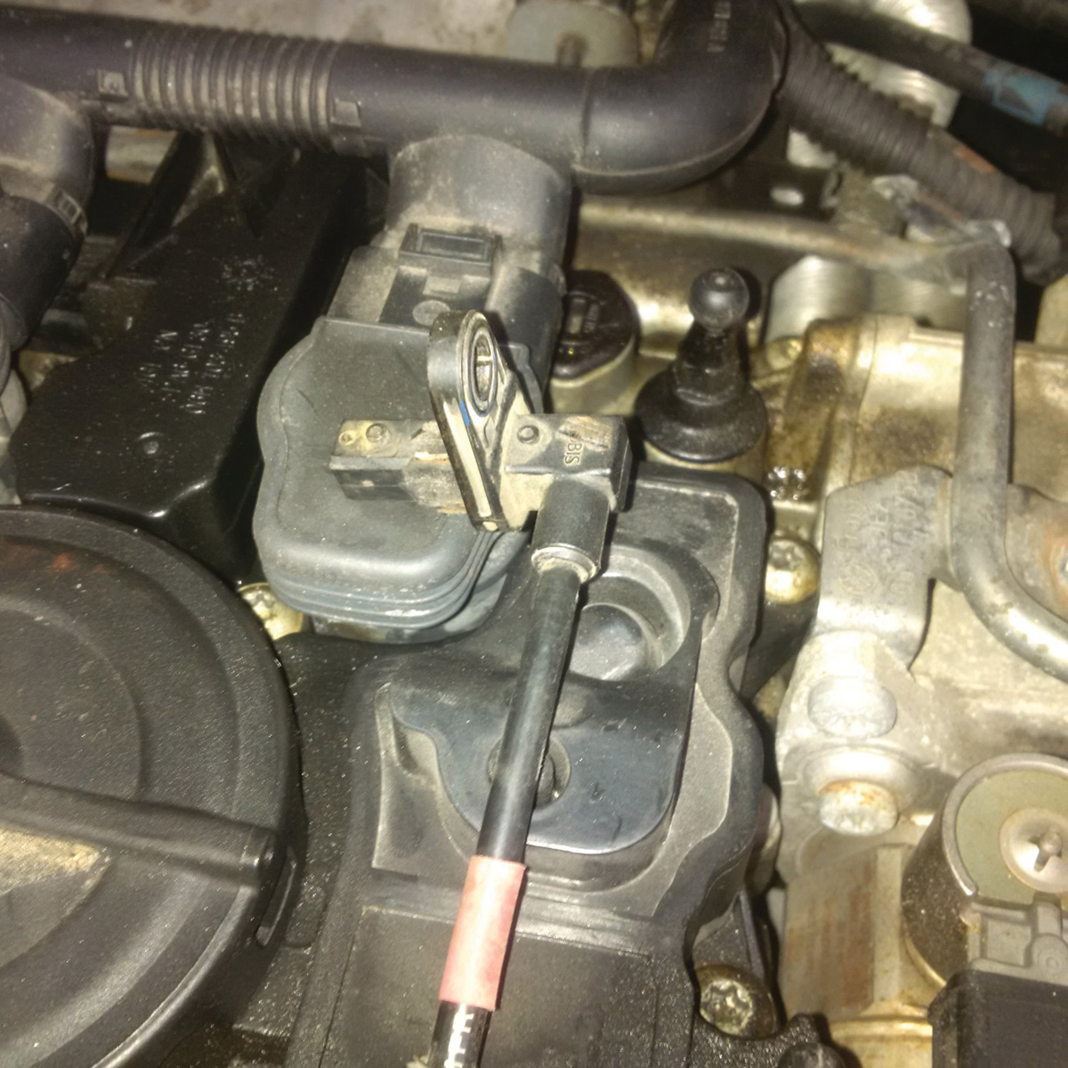
The Mercedes-Benz version looks like this version before it was “carved†and the Kia was different because of the “right angle.†Before any “manipulation†of the original structure, they were tested with the oscilloscope.
The easy button
There were two curiosities:
- Can the speed sensor have another purpose;
- Wondered what the signature looked like when testing an ignition coil(s).
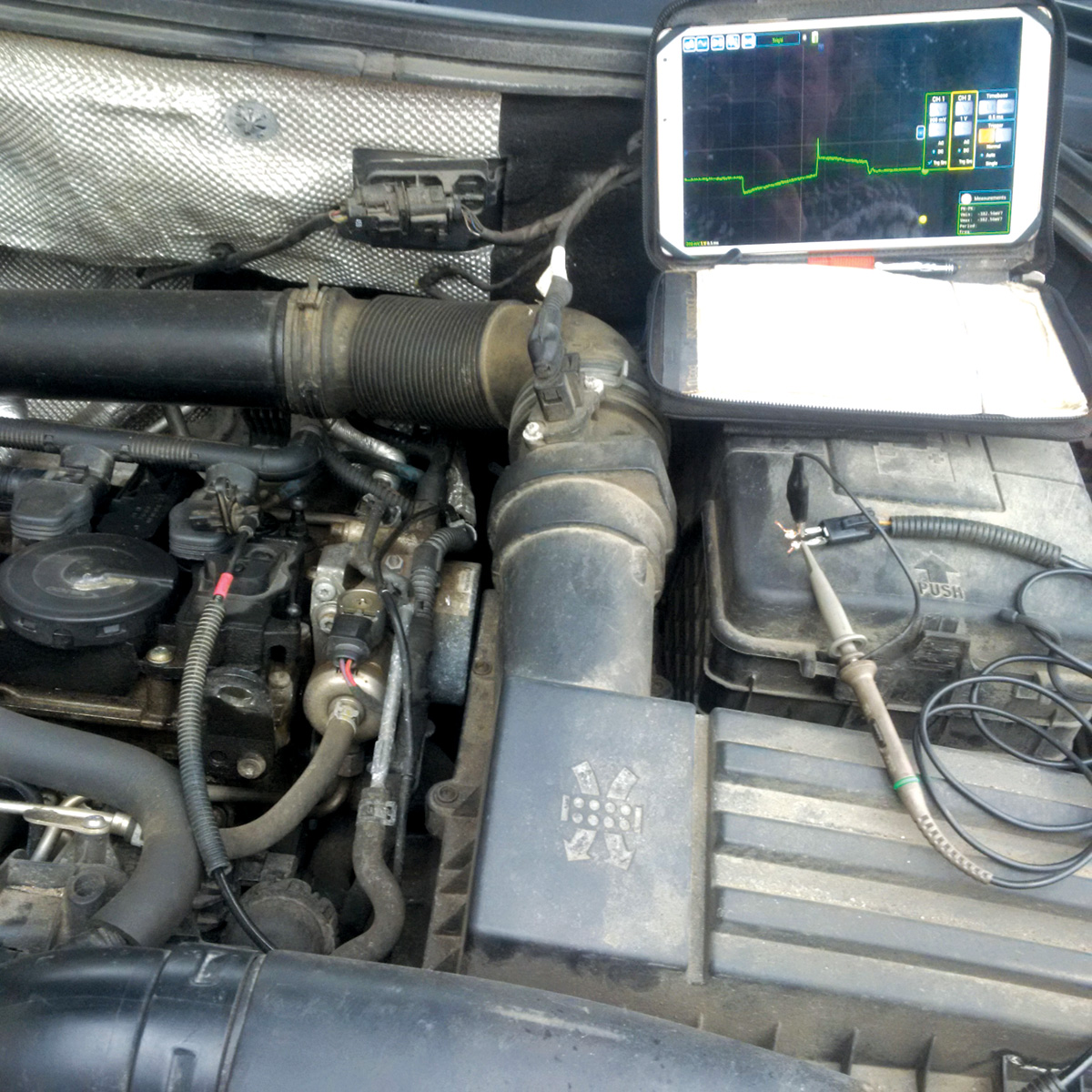
This quick test offers a view with the Kia speed sensor and tablet.
The screen capture is with a professional sensor. Notice the difference while testing the 2.0L Tiguan COP at idle.
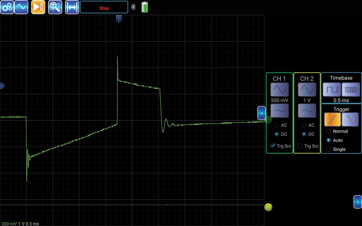
This test indicates a proper waveform signature of a COP ignition coil at idle. There are many versions of COP capacitance ignition coil testing equipment on the market and this version might work quite well on a “little scope.†This same tool works identically on a 4 channel and an 8 channel oscilloscope.
The Pro version has 1000:1 attenuation.
The speed sensor was captured and saved for a test.
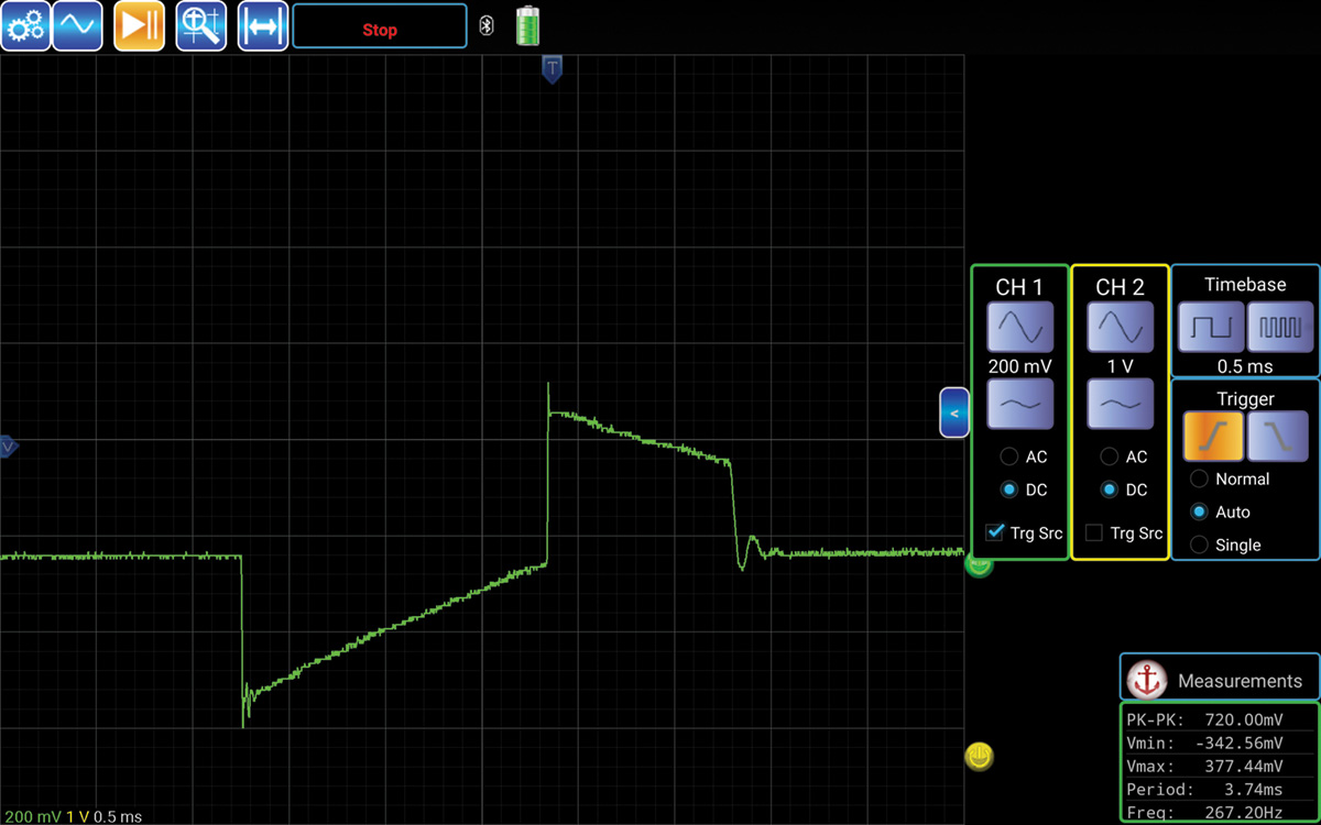
The difference is with the details of the image, but the idea works with a component destined for the garbage or landfill site. If there is no access to a Pro version, beg, borrow, or steal a speed sensor and try it. This image is not perfect by any means and screen captures will differ slightly, especially with the “inductive kick,†but do pay attention to the screen.
The test is more a curiosity than anything else but note how the image displays the correct COP signature. This version of COP signature is distinctive with the Turbo Direct Injection Engine that is also shared with the Audi model.
How does it work?
This particular version of COP is comprised of four connections. Each connection is as follows, but also read the schematic to follow the paths to Battery Positive, Battery Negative, ECM Control for the high speed switching transistor (amplifier), COP ground connection after the high speed switching transistor (amplifier), and the coil secondary for the spark plug.
With the engine running or KOEO, battery power is supplied to the switching transistor and primary side of the coil Pin 1. The ECM control is sequential at each coil Pin 3. Ground connections for the high speed switching transistor (amplifier) are at Pin 2. All coils also have a ground connection at Pin 4 as a monitored confirmation to the ECM.
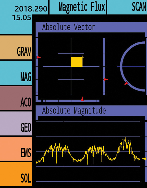
During a training session, we spoke of magnetometers. There was an application found some time ago and used it more as a “gag†with acquaintances. The application has a few interesting features that utilize built in sensors such as: Measuring light intensity, the WiFi or Cellular transmissions, the GEO location with the GPS, a Sound Analyzer, Magnetic Flux (exactly), and G-force or acceleration. This application works on an Android device.
The graph in yellow quickly indicates three COP coils as the tablet or phone was gently moved/slid across each coil. How interesting is that!
THIS IS NOT a recommenced tool during prolonged use!
All kidding aside, the madness is to get a quick image of how one or more ignition coils behaves with a scan tool. The professional tool does have clear advantages of clarity and accuracy.
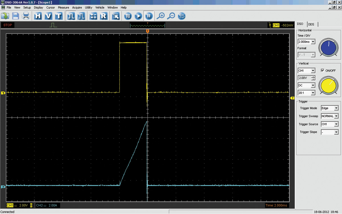
The diagnosis changes when the capacitance probe may not display the waveform needed because of the coil structure or placement. A more in-depth view is required by probing the harness at the COP ignition coils. The following view displays what the ignition coil inputs are with a four channel oscilloscope.
Yellow signal channel 1 (ECM trigger) is set to 2.00 V and 2.000 ms per division.
Blue signal channel 2 (current ramp) is set to 2.00 A and 2.000ms per division.
In the next article in this series, we go deeper. It will be a real eye opener!


0 Comments