
You may know his name, and may have encountered his work. But do you really know him?
The Porsche 911 was, and continues to be, one of the most iconic and long-lived designs in automotive history. The basic outline of the car, its distinct form designed by Butzi Porsche, has come to define the quintessential sports car. Every bit as enduring as the fundamental design of the car itself, however, is the powerplant that drives the beast. Without the innovative, robust engine that many have come to know as the “Mezger Motor,†it could be argued that the Porsche 911 would not have enjoyed its lofty status as one of the, if not the, best overall designed vehicles in automotive history.
Among old school Porsche techs, the term “Mezger engine†may have initially been a bit of a surprise as it has not held a distinct definition until recently. Many writers and folks in the Porsche community tend to restrict the term to define engines in the later, water-cooled Porsche GT3 and Turbo models to distinguish them from the so called “internal dry sump†engine that came into use with the introduction of the Boxster and 996 cars in the late 1990s.
But to restrict the Mezger engine definition to just the horizontally opposed, dry sump engines in their water-cooled form is to short change the history of the overall design as well as its enduring qualities. The fact that the basic layout and architecture of the powerplant remain virtually unchanged since this engine was installed in the air-cooled 911 as it debuted in 1964 speaks to the excellence and timelessness of its design.
Hans Mezger went to work for Porsche in the 1950s, and is responsible for many of their most successful powerplants which include, but are not restricted to, that in the original air-cooled 911 as well as the Formula 1 V-6 engine that powered the McLaren effort in the 1980s. This particular V-6 engine helped to usher in the turbocharged era of Formula 1 and represents Porsche’s most successful efforts in that racing venue. Mezger’s indelible imprint has been left on many other designs throughout his career with Porsche and in many ways he has become one of the most recognizable engine designers in automotive history.
The flat, horizontally opposed design of Mr. Mezger’s engine gave it several inherent advantages in making it suitable for its use in a sports car. The horizontal layout uses two opposing banks of three cylinders, where the reciprocating members create a “push-pull†effect, helping to reduce vibrations which enhances efficiency. The engine’s low profile allows it to fit neatly into the low slung rear end of the body design while maintaining a low center of gravity. Finally, the flat design lends itself nicely to be air-cooled, as the fan can blow air directly across the top of the finned cylinders and cylinder heads, effectively removing heat from those critical components.
The lubrication system of the Mezger engine is one of the many secrets to its success in terms of reliability and longevity. Unique to the Mezger engine and only a very small handful of elite sports cars is the dry sump lubrication system. Most conventional engines rely on the sump at the bottom of the engine as the supply source for the oil pump, with the pickup at the lowest point.
An inherent problem with the wet sump design is that, under hard cornering, braking and acceleration, the oil can slosh away from the pump pickup, allowing air to be sucked into the pump, rather than just oil alone. This “cavitation†effect results in a loss of oil pressure, often at a moment when it is most needed, during high RPM cornering conditions.
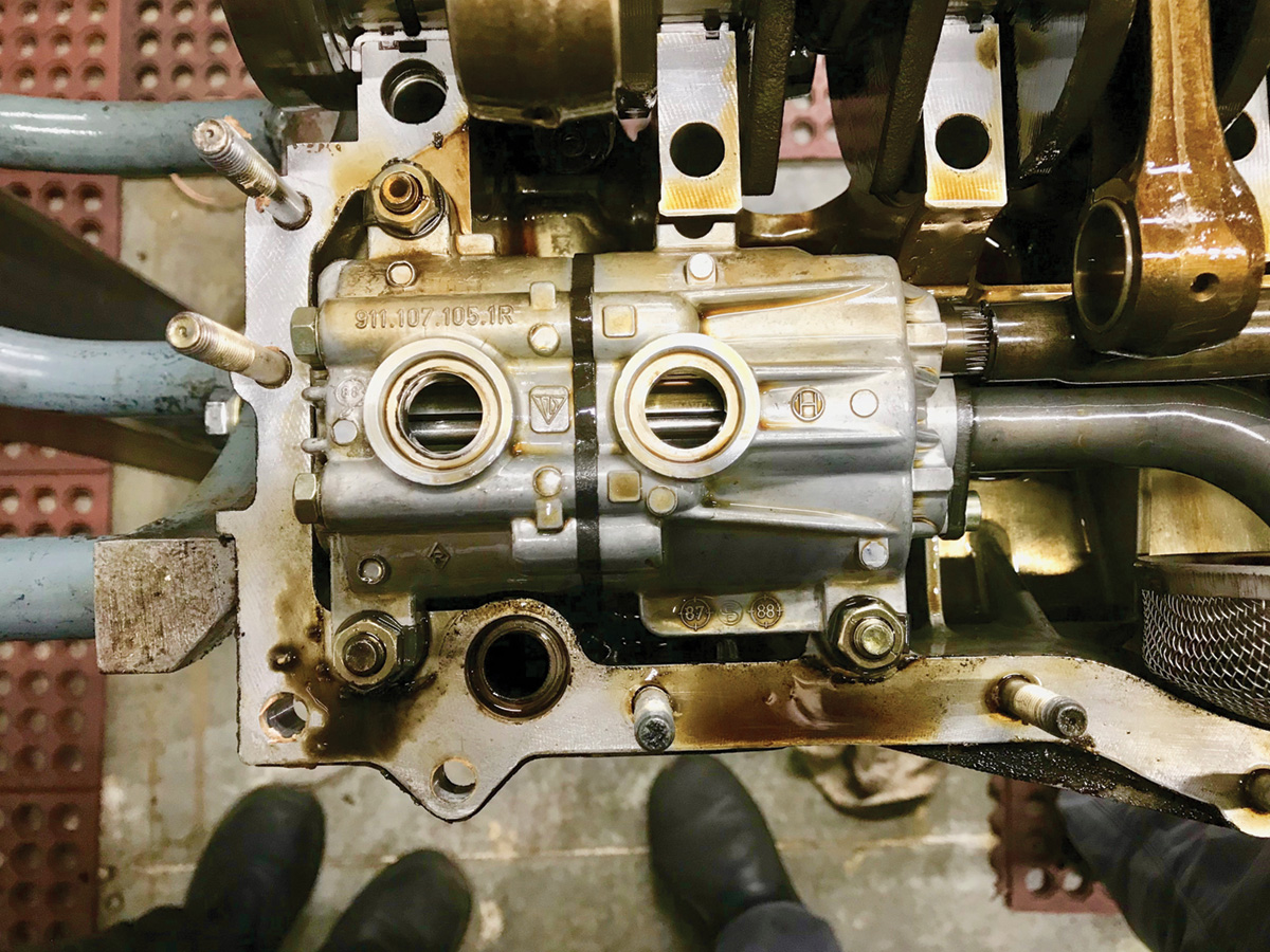
The Mezger dry sump design uses a large, separate and remote oil tank as the pickup point for a two stage oil pump. The smaller section of the oil pump draws oil from the bottom of the tank to deliver oil under pressure to engine bearings, camshafts and pistons to name the main components only. The larger section of the pump serves only to pull oil out of the engine and back to the oil supply tank.
The nature and layout of the dry sump system requires a large amount of oil as it circulates the engine’s life-blood through several large, long lines from engine to cooler (in racing applications sometimes large or multiple coolers) and remote tank. Most street going 911s with a remote front oil cooler require about 11 quarts of oil when it comes time to change, but the entire system contains around 14 quarts.
This oiling system becomes part of the cooling system as well through the use of the oil lines and coolers. The oil tank permits a significant buffer if a consumption problem or leak occurs, as can sometimes happen during a race event. Where a conventional wet sump engine might have a delta of one quart from the “full†limit to the “add†limit, the 911 has a buffer of almost two quarts.
The first two piece engine cases were cast from aluminum, with most of the attached ancillary housings made of aluminum as well. At this point in time aluminum was the preferred material for lightweight engine construction. But the combination of the engine location and a flaw in the chassis design resulted in the first 911s being plagued by significant oversteer problems, which is the tendency for the rear end to break loose during hard cornering.
One of the first attempts at reducing oversteer involved adding ballast weights to the inside of the front bumper. The ballast, however, was nothing more than a band-aid, and it was clear that additional weight savings from the back end of the car would be necessary to keep the rear end from snapping around during hard cornering.
After a couple of years of production, Porsche engineers turned to magnesium for the critical engine castings. The lightweight magnesium resulted in a significant weight reduction at the rear end of the chassis which dramatically improved handling. The use of magnesium, a relatively exotic material at the time, also represented a historic achievement for its time. Mahle, the company responsible for casting the engine blocks, won an award for what turned out to be the largest magnesium die casting of its day. The record-setting right side of the engine case was just over 17 lbs.
The magnesium housings worked well with the smaller displacement engines and aided in mitigating some of the handling problems plaguing the early 911s. As emission standards were increased on cars sent to the U.S. Porsche was forced to increase the displacement of the 911 engine to 2.7 liters in order to keep the horsepower at expected levels.
Along with the need for increased engine displacement came additional heat from emission control components such as EGR (Exhaust Gas Recirculation), AIR (Air Injection Reaction), and the use of “thermal reactors,†which were nothing more than devices that kept exhaust temperatures high as they left the combustion chambers, allowing continued burning of unused hydrocarbons.
But now we’ve added two deadly blows to the lightweight magnesium housings — heat and increased bore size, which narrowed cylinder spacing. The results were that the mag case 2.7 engines were fraught with serious problems such as cylinder head studs breaking and oil leaks…plenty of oil leaks!
In 1978 Porsche made the decision to go back to a stronger aluminum alloy for the material in the engine case.
By the time this switch over was made, other modifications, such as lengthening the wheelbase, had been done to mitigate many of the oversteer problems. However, there were a few other issues that continued to dog the air cooled version of the Mezger engine:
Chain Tensioners
The long chain running from the countershaft out to each overhead camshaft needed to be tensioned by a device that would compensate for a considerable amount of expansion as the engine warms up. Several early designs were utilized but failure plagued this component. One long-standing design incorporated a tensioner with an internal reservoir which allowed engine oil to migrate from the reservoir portion of the tensioner out to the tensioning portion as length change required. Several versions of the same concept all proved to be unreliable.
It wasn’t until Porsche redesigned the chain tensioner to utilize the engine’s lubrication system to feed oil under pressure to it that they became reliable. The upgraded tensioners were used starting in 1984, and the earlier engines could be upgraded to the newest style pressure fed units. Updating involved changing camshaft oil lines with ones that had a tee which fed an additional oil line, which provided oil through a hole in the chain housing cover and to the tensioner body. This upgrade became so popular that today it is rare to find any air-cooled, Mezger designed engine without them. The new chain tensioners are almost completely reliable.
Head Studs
Cylinder head studs on the air cooled engines thread directly into the engine block, then run through the fins on the cylinders and eventually clamp the cylinder between the head and the block. The early, small displacement engines (2.0, 2.2, and 2.4 liter) used conventional steel studs for this task and they were reliable. However when displacement to 2.7 liters came along, problems related to material design reared their ugly head.
Concerns with matching the thermal expansion rate of the alloy cylinders to the original steel head studs led to the use of a special “Dilavar†material that was designed to expand at the same rate as the aluminum cylinder. The steel head studs did not expand as quickly or as much as the alloy cylinders, causing them to occasionally pull out of the engine case, taking their threads with them. The shortcoming of the Dilavar studs was that they were subject to corrosion and would break after years of use and heat cycling.
Redesigns of the studs included an epoxy coating to avoid the corrosion issue, but the epoxy wasn’t completely impervious to the effects of time and it could fail, exposing the stud to the same corrosion issue.
The latest factory versions of the head studs are threaded the entire length of the stud, allowing them to expand and contract at approximately the same rate as the alloy cylinder. While the latest factory offering seems to be quite reliable, many engine builders now choose high performing aftermarket versions of these head studs to establish reliability and mitigate costs.
Oil Leaks
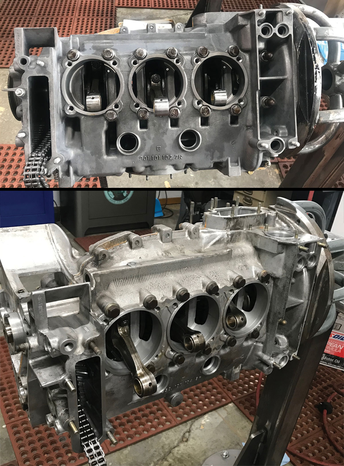
The very design of the air-cooled, Mezger engine can seem like an oil leak just waiting to happen. The engine case is comprised of two halves, which sandwich the crankshaft, oil pump and countershaft between. The assembly of the lower end requires an anaerobic sealant applied to a perfectly clean and flat surface for the two halves to mate up and not leak.
In addition to the lower end, the individual cylinders seal to the block surface, cylinder heads seal to the cylinders, and the cam housings seal to the six individual heads. Now add to that chain housings and covers, oil transfer tubes with o-rings, cam housings, and chain housings to name just some of the main ancillary gasketed surfaces throughout the engine. Porosity and some degradation of the actual magnesium alloy increases the challenge of getting the magnesium case engines to seal. Adding insult to injury, during the mid to late 1970s the engines ran hotter with the addition of many new emission control devices, which essentially cooked many of the gaskets and caused premature failure.
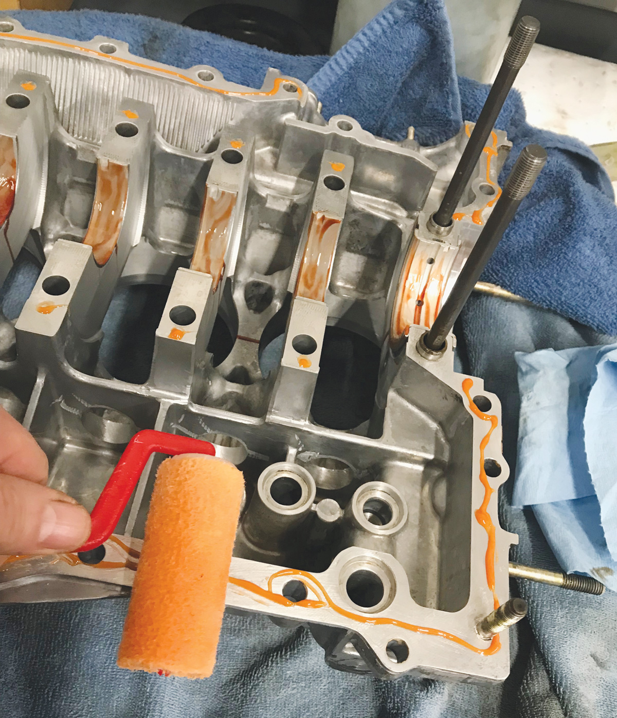
Improved gasketing and sealants greatly improve the chances of having a leak free outcome when assembling one of these engines, but attention to each surface is vital to a successful outcome. Some Porsche engine builders are hesitant to guarantee an absolutely oil dry engine upon completion, especially when using a magnesium case.
A discussion with each customer about his or her expectations of a leak free outcome is an important detail when planning a rebuild. Many Porsche techs will discuss the option of using a later aluminum alloy case if one might be available at a reasonable cost. It is certainly not impossible to rebuild one of these air cooled engines and have no leaks. Longevity of the final product is what is at issue. It is impossible to guarantee any engine to be leak free for an indefinite future. Nonetheless, by using the latest, improved anaerobic sealants and gasketing material as well as keeping the highest standards for cleanliness, you can assure the best possible outcome.
Structural Issues
Most of the serious issues around the early air-cooled Mezger engines had to do with how fundamental components, such as the engine case itself, held up to stress and time. As previously mentioned, this is especially true with the 2.7 liter magnesium case engines. Disassembling one of these engines after running for many years and thousands of heat cycles, or hitting above the 100,000 mile mark, almost assures that some structural issues must be addressed. The constant side to side loads of a reciprocating engine on the crankshaft will ultimately distort the main bearing bores, making it often necessary to line bore the engine case main bearing bores.
There are two approaches to line boring. The first method requires shaving the case halves down, which reduces the main bearing bores sizes, and then re-boring the main bearing bore to the standard dimension,. The second method is to just bore the main to an oversize dimension and fit the case with oversize main bearings. The latter approach has become less popular as oversize bearings have become scarce and expensive.

“Shuffle pinning†the case halves at the main bearing bores is another procedure which helps strengthen the main bearing area of the engine. This modification involves drilling blind holes which then receive tight fitting dowels on either side of each main bearing saddle near the holes for the case’s through bolts.
The dowels serve to mitigate some of the “shuffling†effect of the two case halves as they are exposed to the loads of reciprocating mass at high RPMs. Shuffle pinning isn’t typically necessary on a street engine but is a good idea if one of these engines is being driven at race tracks where sustained high RPMs are common.
Another requirement when rebuilding a magnesium engine case is to install steel thread inserts for all of the cylinder head studs. While this work can be done carefully by hand, it is done most accurately and cleanly on a mill where drilling and tapping can be held to a higher level of precision.
The needs of building an engine for full out competition at a race track are very different from those of a concours or restoration project. The selection of updates or modifications to any air or water-cooled Mezger engine requires research and collaboration with the customer. Maximum displacement, higher compression and sustained high RPM and load usage require adding as much strength to the basic engine as possible. On the other hand, rebuilding an engine to exacting original appearance in a 911 that will see only a few thousand miles of street use requires only a few updates for a reliable outcome.
Engine Evolution
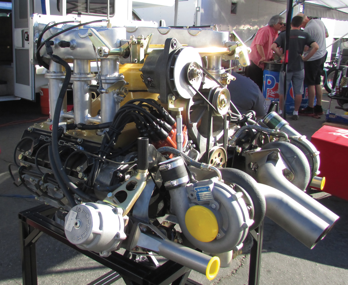
The air-cooled version of the Mezger designed engine continued to grow in size as more power and emissions added stress to the basic design. In fact the engine, which started as a relatively small 2.0 liter displacement, grew to a 3.8 liter displacement in its final form. The very same engine received turbocharging starting in 1976, then went to twin turbos in 1996, and eventually made 424 horsepower in the relatively rare Turbo S version.
The result was that the turbocharged cars were capable of 0 to 60 times of 4.5 seconds while the full on racing version GT2 could get from 0 to 60 in under 4 seconds. These kinds of performance numbers put the Mezger powered Porsches squarely in the ranks of elite supercars.
Next month, the Mezger engine becomes water-cooled.
Download PDF


0 Comments