
2.0L TFSI Automatic Transmission AWD
| Tools used: |
| Ross-Tech VCDS |
| 90 amp power supply |
| Oscilloscope with tablet |
| Multi-meter and amp clamp |
| Camera and note paper |
For the uninitiated technicians working with VW models, the data, images and observations for the vehicle being discussed here are real world including a personal vehicle. The vehicle does not have any issues or faults with the Haldex 4Motion, but the article offers observations, service procedures and undocumented output/live tests.
Hand in hand, associate this article with the previous “The DVOM and Signatures†piece from last issue. This new article employs a few methods to test the Haldex system with various tools. Regard the data, images and illustrations as representative of a working faultless unit and a guide to future repairs.
Note: Remember to scan the entire vehicle and save it including all subsequent scans while performing any service or repairs.
Who uses Haldex?
Over the years that the 4Motion Haldex system has been in service, many versions have been used, achieving great success. The system has been used with VW Group, Volvo, Saab, GM, Ford and Land Rover models.
In 2011, the Swedish Haldex Traction AB division was acquired by Borg Warner.
What does this generation look like?
Before engaging in any type of work or diagnosis, the system(s) should be understood as to the design and how the system(s) are intended to work.
One simple way to know what systems are inter-connected is using VCDS to see the activity of the networks connected to the Haldex controller.
By accessing the VCDS at address 22 and function 08 measuring blocks, read and view groups 125 and 126.
| Group 125, Field 0,CAN-Data Bus Communication |
| Group 125, Field 1,Engine *J623 Control |
| Group 125, Field 2,Transmission *J217 Control |
| Group 125, Field 3,ABS *J104 Control |
| Group 125, Field 4,Instruments *J285 |
| Group 126, Field 0,CAN-Data Bus Communication |
| Group 126, Field 1,Steering Angle Sensor *G85 |
| Group 126, Field 2,CAN-Gateway *J533 Control |
All groups should indicate 1 = Active on the network
Any group indicating 0 = Not active on the network
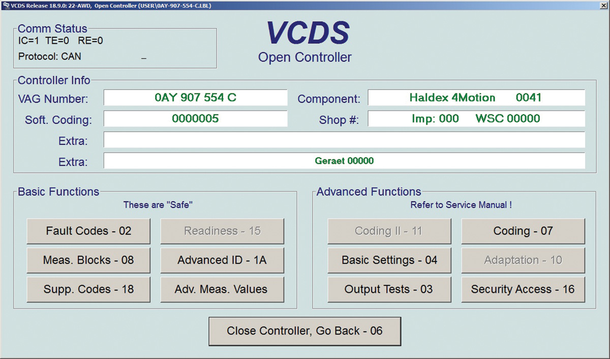
The image describes important data such as: Controller part number, Component and software version, Controller coding and the Work Shop Number that LAST coded the controller. A VW or Audi dealer that codes the controller will have its number within that field. VCDS will accomplish that task in “stealth mode.â€
Search for the “VW Coding Mysteries†article with an interesting explanation of “who LAST coded the controller.â€
Generation IV Attributes
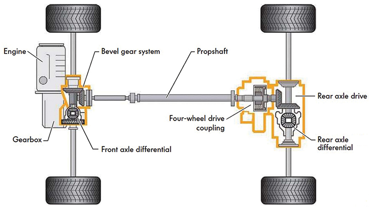
Similar to earlier generations, the Haldex controller applies the driving force via a set of clutch plates. Compared to previous generations, a new feature added is building pressure via an electric pump while J492 determines the amount of torque transferred to the coupling opening control valve N373. This version no longer requires the speed differences between the front and rear axles to start the coupling in support of four wheel drive. The system is compatible with traction control systems within the ABS and ESP systems.
This version uses an electric over hydraulic controlled clutch plate with an optimized and demand-regulated pump control. Drivers can now expect a seamless and instant engagement by means of pre-control. Consider pre-control as Engine Torque via throttle application.
Service bay tests and what should be in view
When the engine is started and reaches 400 rpm, the Haldex pump V81 is activated. Via the oil filter to the accumulator, V81 moves oil until a pressure of 30 bar, or about 435 psi, is reached. N373 (coupling opening control valve) is closed by J492 (Haldex) in order that the working pressure is applied to the working piston and pressing the clutch plates together.
On acceleration, the full rear axle torque is available immediately.
During Haldex activity, constant system pressure between the pump and valve is held at approximately 30 bar, or about 435 psi.
N373 (coupling opening control valve) controls the working pressure and sets the applied pressure as required.
Working pressure can be between 0 perecent while braking and 100 percent during acceleration.
A raised hoist test is one way to determine if the Haldex system will engage. The issue can be wheel speed differences when one or more wheels drag slightly with either or both differentials active (spinning at different rates). It will happen on the hoist, so expect the ABS to intervene quickly at any of the four wheels. An operating Haldex will engage the rear wheels and pressure will be seen on the VCDS screen when reading Address 22 values. The hoist test is certainly NOT a road test.
So what would happen with all four wheels on the ground, safely parked and the electric parking brake applied? Place in Drive with slight torque for a few seconds. Pay attention to the vehicle creeping and or obstructions.
| Play this smart and safe – Know exactly what you’re doing and be in TOTAL control. |
Pay attention to the screen and apply the throttle ON slightly to OFF. Wait 10 seconds and apply slight throttle again for a few seconds, read the screen and let OFF again. Notice the changes on all four fields.
Note: Do NOT over heat the transmission or the Haldex coupling during this test or repeating the test multiple times. Can anything be read of interest if there were faults?
The digital view
The information supplied by VCDS and the people that write the descriptions offer a view of what some of the “digital signatures†mean in real time. The digital display can be a great aid if the Haldex recorded or logged a fault.
If there was a fault recorded at Address 22, there are a few digital signals to look at if that fault was monitored. When a fault was recorded, make note of the fault(s) and look at the monitoring values.
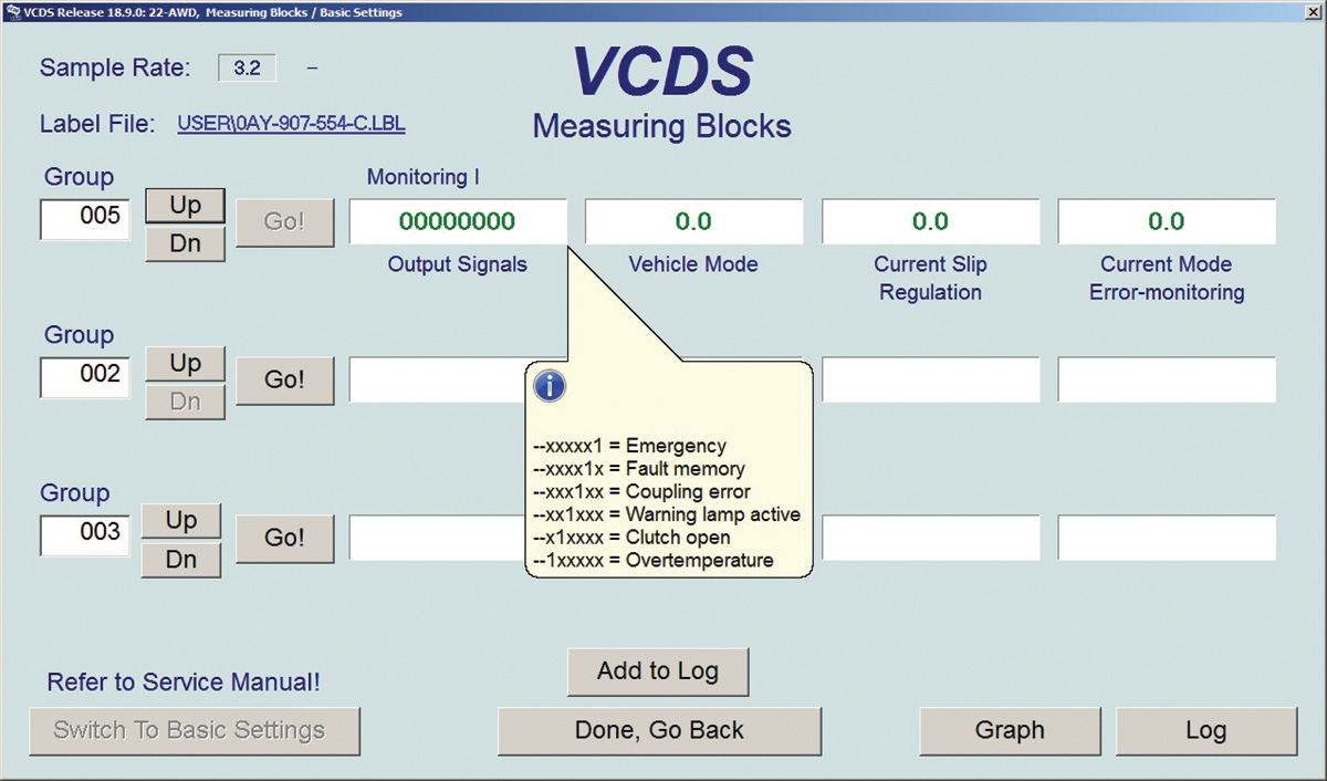
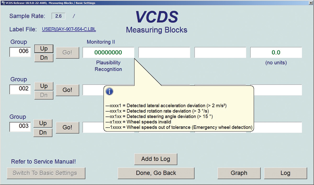
Hint: Earlier in this article, CAN-Data Bus Communication was described at groups 125 and 126. This will also mean that IF there were faults recorded at any other controller that is associated with the Haldex, there may be a chance that one or more digital signatures may also be active while monitoring groups 005 or 006. In the case of Group 005, the digital signatures appear to monitor the Haldex itself.
In rare occasions, there have been one or more controllers that switch the display in groups 125 and or 126 from 0 to 1 and vice versa while in view every few seconds. Switching digits will indicate a CAN network communications error for that controller and/or the controller that VCDS is logged into. If that is the case, repair that error/fault first before proceeding with Haldex diagnostics.
The majority of Monitoring II can be associated with the ABS. If the ABS is sending garbage data, then the Haldex will react to garbage data. Don’t blame the Haldex for recording faults that may be associated with the ABS or even the engine controller. Measure the affected/connected controllers.
The next image is Monitoring III and the data read via CAN from the engine and ABS controller. If there is a discrepancy, monitor each controller(s) and match the values under identical test conditions.
Note: Any and all ABS faults must be repaired and cleared before attempting any basic settings or adaptations.
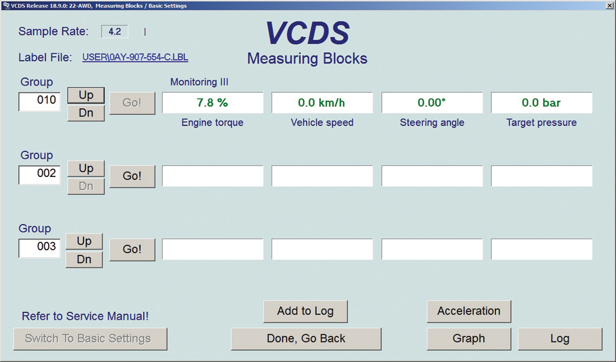
Groups 011 to 012 (Monitoring IV and V) also display data via CAN as an aid to monitor what messages are sent to the Haldex. It is these CAN messages that will operate the Haldex system as per design.
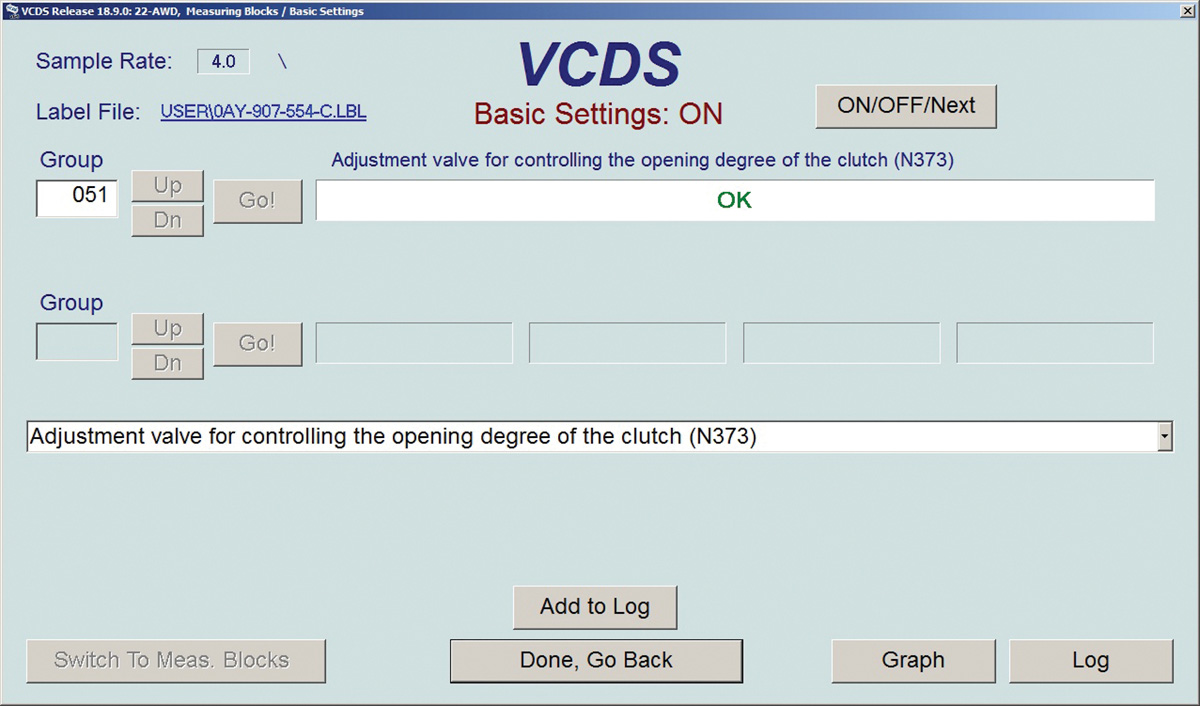
If for any reason any components or parts have been replaced and/or having cleared a Haldex fault, set Basic Settings at group 051. Recording a mixed highway and city drive or with another technician has advantages.
How many ways to measure the Haldex?
Use VCDS, a multi-meter or an oscilloscope attached to an amp clamp.
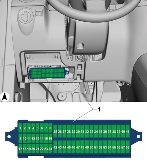
The interest was to “monitor†the Haldex with shop equipment and keeping it simple. This test is at the 10A fuse below the driver panel. Open the cover to expose the fuse box and attach a loop in place of the fuse. Attach the amp clamp to the multi-meter and view both the meter and VCDS.
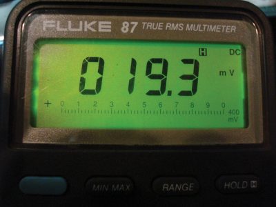
The meter reading changes with a key cycle, engine start, and application of the throttle in Drive or Reverse (electric parking brake applied). The test measures current that is consumed by the Haldex controller. A simple road test with another technician offers much more detail.
The fuse panel illustration locates the fuse position, with the following image indicating the amp clamp connected to either multi-meter or oscilloscope. The correct fuse using a schematic is S10.
Keep it simple
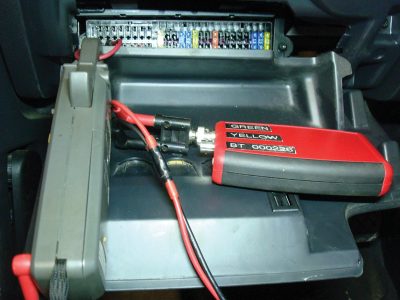
Switch the meter with the oscilloscope while viewing VCDS and notice the similarities of digital data compared to the waveform. Note that the 10A fuse powers the Haldex controller. The Haldex controller also controls solenoid N373 and Pump V81.
With VCDS and a tablet with Bluetooth oscilloscope, the needed information and testing can be accessed quickly via the 10A fuse. Be aware of connections and equipment during any tests, especially a road test.
This choice was accessibility when connecting at the 10A fuse. The consideration was NOT disturbing the connection between the pump and Haldex controller for the moment.
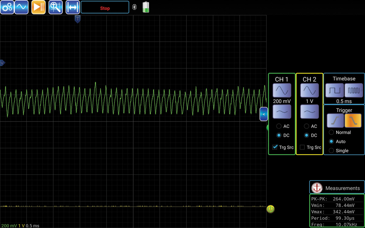
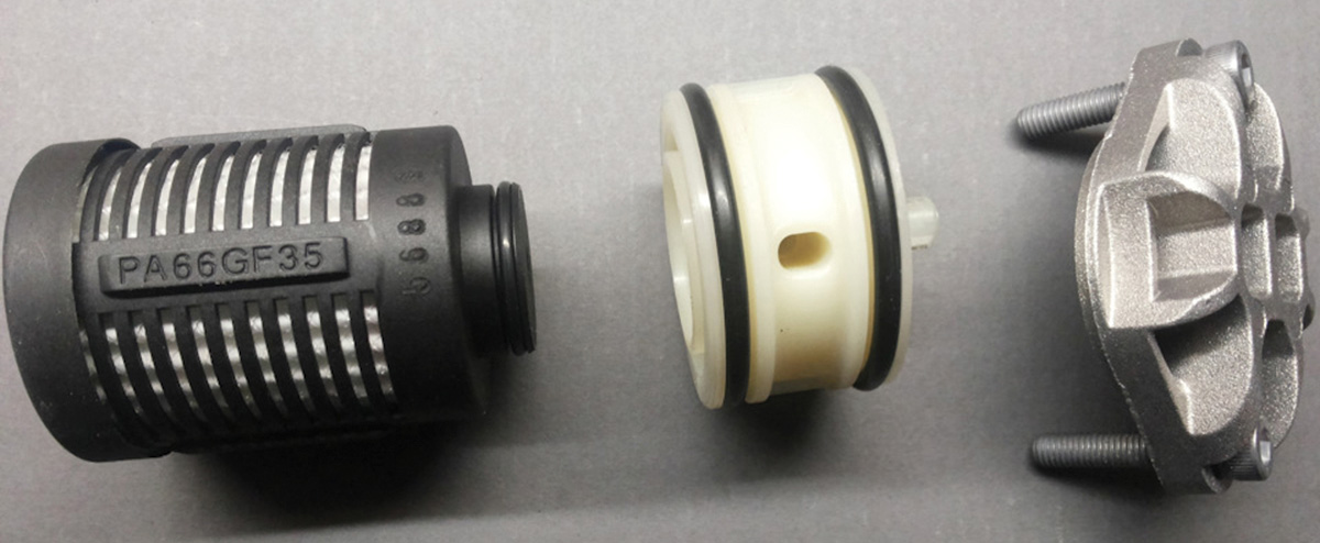
The following image looks similar to that of a fuel pump. The association is the Pump percentage and Pump current on the scan tool. When viewing the waveform and applying gentle throttle, the speed of the pump and current is drawn onto the oscilloscope screen.
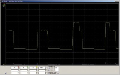
The last method besides viewing the VCDS measured values is using the VCDS graphing feature. Match either the multi-meter readings or oscilloscope waveform with this VCDS feature. Choose the correct measured value and again, test with throttle inputs without creating any damage to the running gear or the vehicle.
One last mention is to help understand the software and clutch control this generation Haldex is designed with.
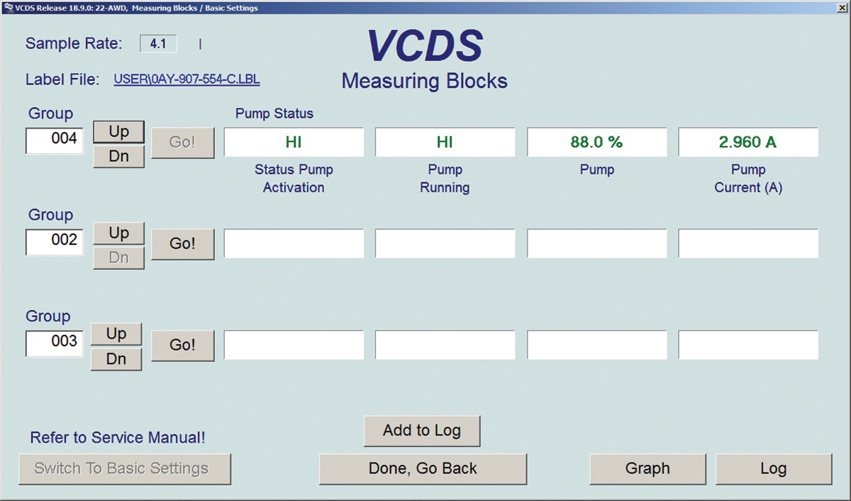
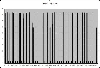
Using VCDS, a road test with mixed driving can be recorded and saved by logging the group(s). Using Microsoft Excel or similar software, the recording is read. The most interesting group is 004 but others can be included.
Saving the file after the road test produces the output of group 004 or any other group of interest.
What needs to be tested is rear axle torque under different conditions. The conditions will include acceleration, highway speeds, braking from different speeds, full brake stopping and slow speed parking maneuvers.
If the intent is to use the recorded file, it is found within the Log folder of VCDS. Highlighting the data in question can be graphed with Excel or equivalent. During the road test and keeping in mind “axle torque under different conditions†offers a clear image of how the Haldex behaves.
Put that road test to good use
If this version/generation Haldex is arriving at the repair facility, why not record its behavior? If the road test is attempted for repairs, use a mixed highway, city and a few stop-and-goes that are repeatable.
How many ways can the Haldex be measured? Simple service and profitable
Servicing the Haldex unit is a simple task and recommended. The opinion is based on use and abuse due to driving conditions. Use the proper service literature with the correct oil specifications for the Haldex unit and differential unit. Each takes specific oil.
Remember: Search for all available TSBs and Dealer Campaigns associated with the vehicle.


0 Comments