

Electrical issues may be the most difficult category of diagnostics in the modern automotive industry. From body shops to lube bays and every repair shop in between, all of us have to be aware of the sensitive nature of the rolling computer complex that represents today’s vehicles. Let’s look at a few examples of electrical diagnoses gone wrong and getting to the solution without making things worse.
Breaking out your multimeter and test light then tapping into wires haphazardly is a scary proposition. The sensitivity of the on-board computers we are working with is a danger we should always be aware of. Sometimes testing with the proper equipment in the proper way can still result in problems.
As connectors age, the plastic gets brittle and can break. While reaching into a tight engine compartment, vacuum connections can break off, coolant leaks can manifest, and other brittle plastic parts can crack. If we can get to the solution to our problem without getting too involved in electrical testing, we’re much better off.
Let’s take a look at some examples of common electrical problems. Although we do, in fact, want to get the repair done quickly, our goal is to get the car fixed properly. Rushing a diagnosis, guessing, skipping steps, and taking certain short cuts can get you there quickly or can lead to disaster. That being said, if you run into these particular problems, perhaps these examples will point you in the right direction and save a bit of time.
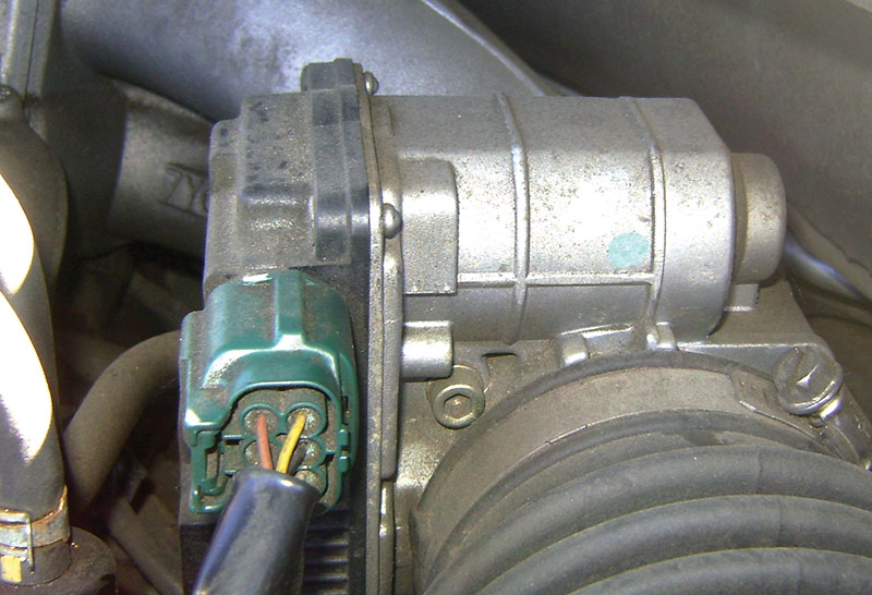
There’s a 2010 Frontier, 4.0L V6 in a shop for a tune-up. The technician pulls the intake plenum to get access to the right side spark plugs. Mistake number one, he unplugs the throttle body and MAF sensor forgetting that he left the key in the run position. As he’s finishing plugging all the vacuum lines back in and started torquing the plenum bolts, he sees the throttle body looks dirty.
Grabbing a rag and some parts cleaner he pushes the throttle body open and wipes all the carbon out from around the throttle plate. Once the engine is re-started the engine is racing and won’t settle down to an idle. Now the idle is bouncing from 2,000 to 3,000 rpm, the Check Engine light is on, and the technician is just about to panic, not knowing what to do next. Scanning for codes he only finds the codes he caused when he unplugged the throttle body while doing the tune-up.
This scenario isn’t common but does come up from time to time. The first instinct is often to grab the multimeter and start testing the throttle body motor and throttle position sensors. Unfortunately, this will end up being a big waste of time. Although the values can be manually tested or observed in the data stream, if they were actually in error it would quickly set a DTC.
The throttle position sensor has a redundancy to ensure that, if there are any failures, the ECM can go into safe mode to protect the engine and driver. As far as the ECM is concerned, it thinks the engine is running correctly. Even though the problem is electrical in nature, it’s not an electrical failure, it’s a calibration error.
With a throttle cable actuated throttle body, it’s no big deal to move the throttle by hand. With an electronic throttle body, moving the throttle plate or interrupting power throws off the calibration with the ECM and requires re-calibration to restore proper idle. To make things worse, if the idle is too high or the Check Engine light is on, the ECM won’t allow the re-calibration process to happen.
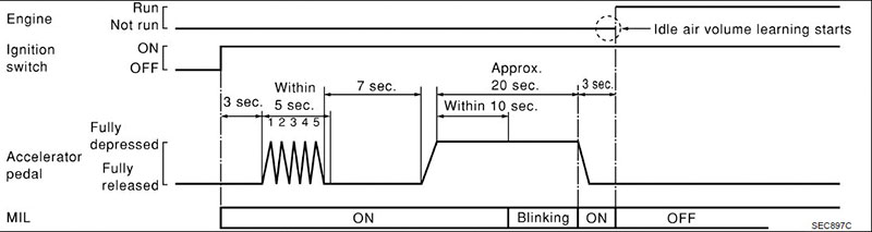
The re-calibration can sometimes be done without the Consult III Plus although, as you’ll see in the following text, the procedure is quite unwieldy. Using a stop watch to keep perfect time, turn the ignition to Run for two seconds, off for ten seconds, and repeat six times, making sure the throttle body moves when the ignition is off the sixth time. The accelerator pedal should remain untouched up to this point.
The next series is a little tougher. Turn the ignition on, wait three seconds, push the accelerator pedal to the floor five times in under five seconds (but not too fast), wait seven seconds, then hold the pedal down for about 20 seconds. The MIL will begin flashing at various speeds. Once it flashes in about one second intervals, near the 20 second mark it will soon turn the light on solid. You must then release the accelerator and start the engine within three seconds.
If you got everything timed perfectly, the ECM will correct the idle within the next two minutes. If not, you get to try it again, possibly many times. When the process is failing because the idle is too high, over 1,500 rpm or so, you can unplug one or two fuel injectors, causing a misfire that, hopefully, will bring the idle down enough to complete the calibration. With the Consult III Plus all of these steps are boiled down to three functions; learning accelerator pedal position, learning closed throttle position, and idle air volume learn.
All this trouble was caused by incorrectly cleaning the throttle body. It seems a little too easy to say, “Don’t touch it if you don’t know what it is.†You might think following this motto means there are far fewer things you can fix. The proper way to look at it is that it’s an opportunity to take the extra minute and learn what you don’t understand about the system.
For example, you don’t want to just leave the throttle body dirty. A much better option is to look into it and find out that you can, in fact, perform an induction cleaning service that addresses the dirty throttle body instead of manually removing the grime by hand and risking damage. As a bonus it also cleans the rest of the intake manifold that, incidentally, is just as dirty as the throttle body. It certainly will take a few extra minutes to look it up in the service manual, but this time is well spent, as it increases your knowledge base and saves you the time you would have spent re-calibrating the throttle body after doing it incorrectly.
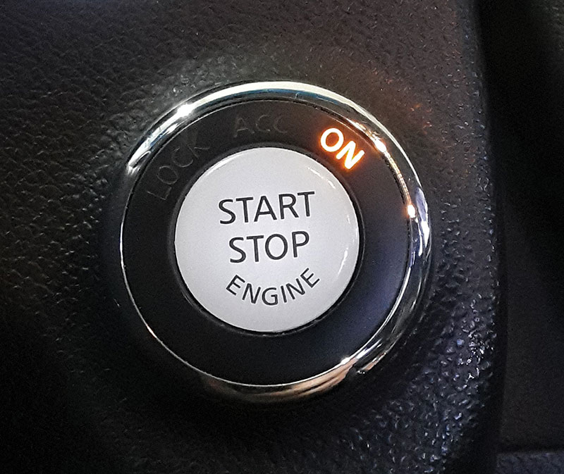
There once was a 2010 Altima that was towed into a shop for a no-start condition. It sounds like the start of a good joke, but its actually a tale of diagnostic misdirection. The customer had the car towed in to have his starter replaced. On arrival the technician, thinking “starter†hopped in the driver’s seat and hit the push button Start. Nothing happened.
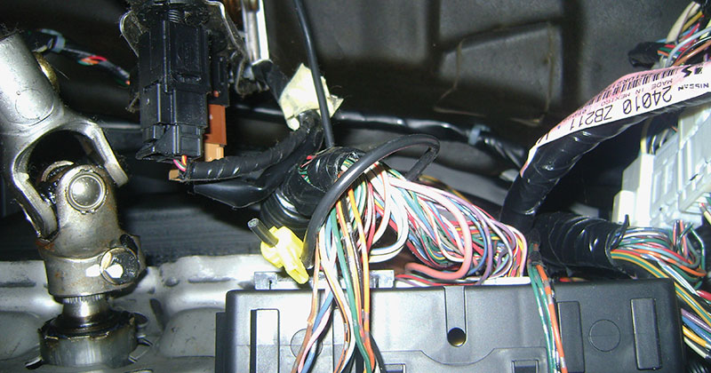
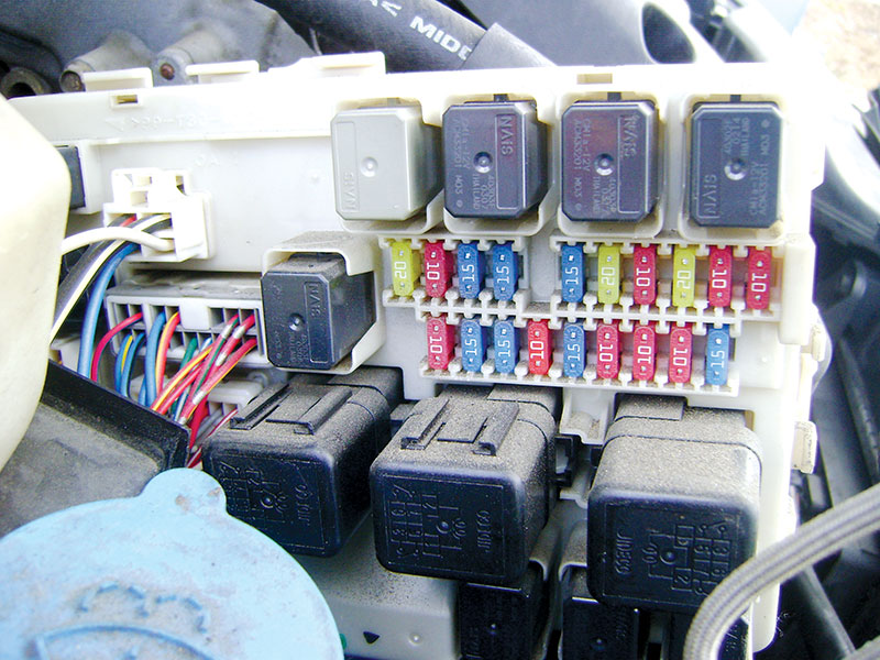
With wiring diagram and power probe in hand, he headed for the IPDM (Intelligent Power Distribution Module) to try to manually trigger the starter at its relay. The starter cranked over without any issues. The technician then surmised the button itself must be bad, since nothing changed when the button is pressed. He digs into the dash to pop the button out and test it, only to find it’s working perfectly. Next, seeing that starter function is controlled by the ECM, he connects his scanner only to find no communication with the ECM. Testing power and ground wires to the ECM, he discovers there is no ignition power supplied from the IPDM.
At this point, our technician reaches for the scan tool to find out what’s going on. If you’re using a standard OBDII scanner for emissions codes, you will be out of luck on this one. Without power to the ECM, a universal OBDII scanner won’t even connect. The codes that will lead us to a solution are stored in the BCM (Body Control Module) and require a more advanced scanner to read them.
Scanning the BCM he finds codes B210A, B2607, B2609, and B2612, all related to the steering column lock, and that is where our problem lies. The BCM looks for an appropriate status signal from the steering column lock and the IPDM steering column relay before it will command the IPDM to activate the relays that supply power to the ignition and accessory relays.
As an interesting side note, when this condition is present it will often appear with the steering wheel not being solidly locked. With this condition you can easily overpower the steering lock by hand. There is a diagnostic chain to electrically test the steering lock before condemning it. However, you can often give it the “bad starter†treatment to confirm this fault. Just lightly tap on the steering lock, under the dash, on the steering column. If the ignition now comes on with the push button, you’ve confirmed you need a new electronic steering lock module.
A nice thing, it’s a plug and play device that doesn’t require programming. There is an aftermarket part available, but you can get the genuine Nissan part, 48700-9N00B, for about the same price. So, don’t take the chance, get the right part.
Human interference in the natural function of an electrical circuit is, by far, the scariest of all diagnostic procedures. When aftermarket components are installed you won’t have a diagnostic chain or even a wiring diagram to go by to determine the fault. On top of that it usually isn’t even clear that the aftermarket installation is to blame for the problem.
There once was a nice couple, in their golden years, that was towing their 2013 Sentra as a dinghy behind their motor home when they toured the country. As they set up camp in a certain city and proceeded to drive their car around town, they found that it would surge dramatically, but only when the turn signals were on.
Where do you even start with this diagnosis?
Let’s start with a test drive. With careful observation the technician notices that, at a stop, the turn signals have no effect on engine performance. The engine surges dramatically, however, under acceleration, timed with the flashing of the turn signals. From this we can assume power from the turn signals is influencing the ECM in some way. Checking for codes, the technician finds that the ECM thinks it’s trouble free. Looking at a wiring diagram we find no connection between the exterior lights diagram (turn signals) and the ECM.
The next step in this diagnosis is a careful observation of the data stream looking for any PID (Parameter IDentification) value that changes in time with the turn signals. The first time looking through the list, sitting in the driver’s seat, the technician finds nothing noteworthy. He then gets out of the car and goes through the list again while looking under the hood. Scrolling through the list he notices the brake switch is turning on and off with the turn signals. While sitting in the driver’s seat, he naturally had his foot resting on the brake pedal making the switch indicate a steady on condition.

Further inspection found that the brake lights were flashing with the turn signals in the rear. The interesting predicament is that the ECM-controlled throttle body will not allow the engine to accelerate while the brakes are applied. As power is applied to the brake switch circuit from the turn signals, the ECM is fooled into thinking the brakes are being applied and it closes the throttle, thus the surging.
The brake lights on this model are LEDs and the turn signal bulbs are traditional incandescent. Initially it would appear that the turn signals are back feeding through the brake lights, perhaps due to a faulty ground.
On this system that isn’t possible since the brake lights are LEDs. The “D†stands for diode and electricity can only flow one direction through a diode. Power from the turn signals must be coming into the circuit between the brake light switch and the brake lights. The diagram only shows two joint connectors and a splice for the center high mount stop light in-line from the switch to the lights, making a failed part somewhere unlikely.
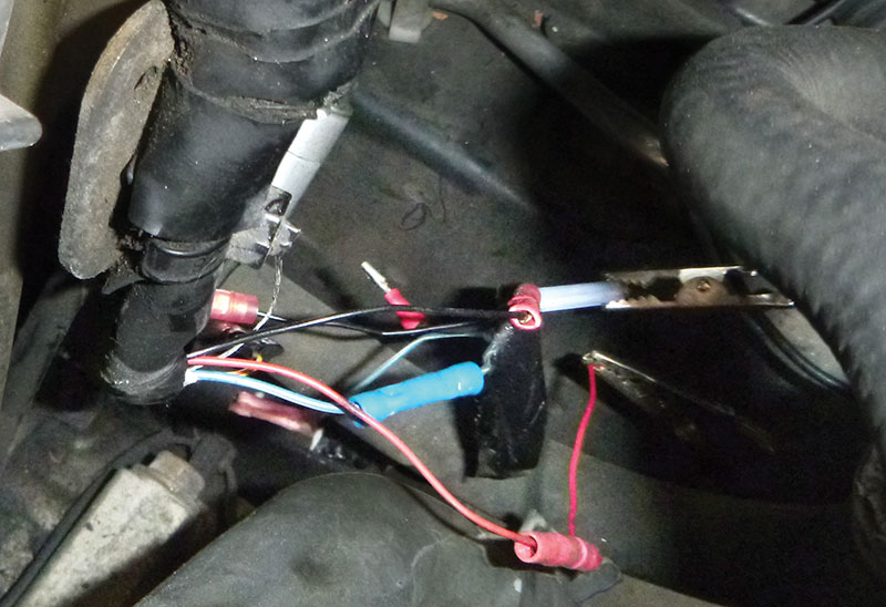
Further investigation found the lighting connection for towing as a dinghy wasn’t wired in properly, and it tied together the brake lights in the rear and the turn signals in the front. When the turn signals were used, electricity fed back through the aftermarket wiring and powered the output side of the brake switch.
Wiring for dinghy towing is an advanced modification and splicing into the vehicle’s wiring harness should be avoided if at all possible. External magnetic tow lights would certainly be a better choice.
These are three examples of electrical problems that are difficult, if not impossible, to identify with traditional electrical diagnostic methods. Taking time to know exactly what you expect to find when you touch your test lead to the terminal might reveal your answer without even having to pick up that multimeter. This includes gathering knowledge from the technicians that have come before you.
Time spent checking TSBs and tips from other technicians is often more valuable than ten times the amount of time diagnosing with a multimeter. Please, return the favor. If you can be the advising technician that saves the other technician a three-day nightmare diagnosis, it makes all the difference in the world. It’s better to be competitive by providing better customer service, rather than keeping all the best tricks to yourself.
Download PDF


Great stuff.
This is a good information
@jhdg20 Thanks!