
The reference for this article is a known good coil, with the engine at idle with no recorded faults. The result being: the ECM is in control of the magnetic collapse with sufficient current to drive the transformer.
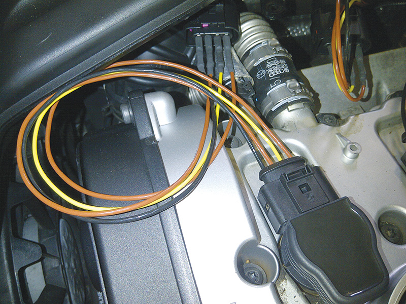
When the VW/Audi models are being tested, the harness itself can be assembled in such a manner that it is difficult to back probe, to move and open. There are no winners in that operation so a “piggy back†set of harnesses was created as a “tool†to quickly test this four cylinder engine.
The earlier article describes the input signal from the ECM and a measurement of the coil ramp. This is one set of harnesses we made so as to not damage the original harness and gather the signals of interest.
Another tool in the tool box
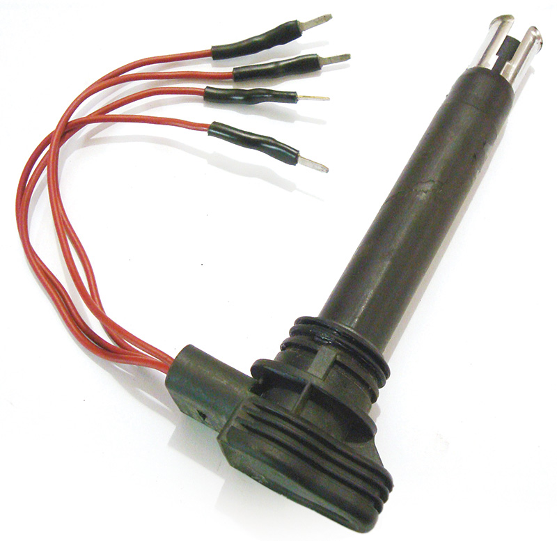
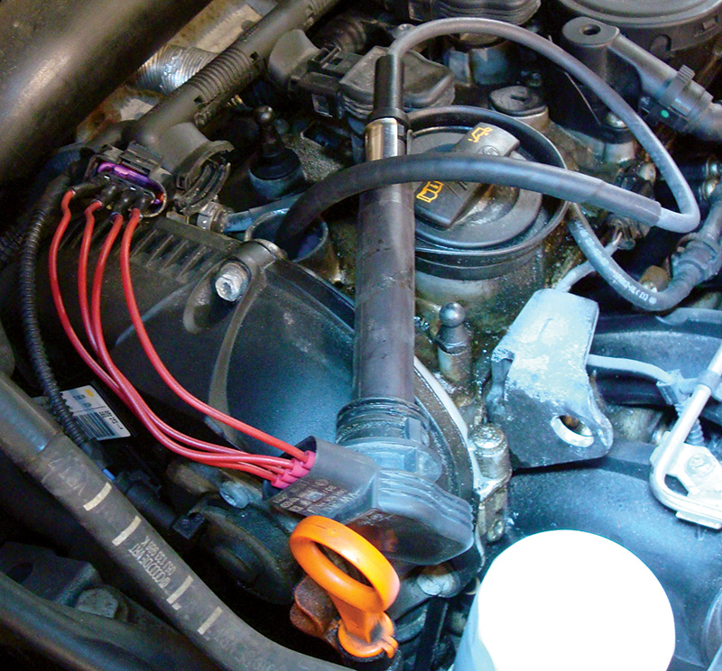
One choice of quality breakout harness is the BREMI brand 20113/40 and required a set of 4. With this setup, there is no damage or manipulation of the original harness and it represents a far better investment of shop/customer and learning time. The BREMI set is a harness repair solution but added perfectly fitting male blades to the original harness connections. This test is on a 2.0L Audi.
Another set of four can be attached to a V-8.
With the “piggy back†harness, the signals can be back probed and you can easily attach a current clamp for precision measurements.
Parts Required |
| Red female blade connector |
| Perfect fitting male connector removed from a damaged and stripped down GM under hood fuse box. (Never throw those out). |
| Wire, solder and shrink tubing |
Tools and test equipment required |
| Ross-Tech VCDS and 90 amp power supply |
| 4 channel oscilloscope |
| Professional ignition paddle |
| BREMI harness repair or purpose built harness |
| Magic wand |
| Tablet with a Tricorder, camera and notes |
What about the paddle?
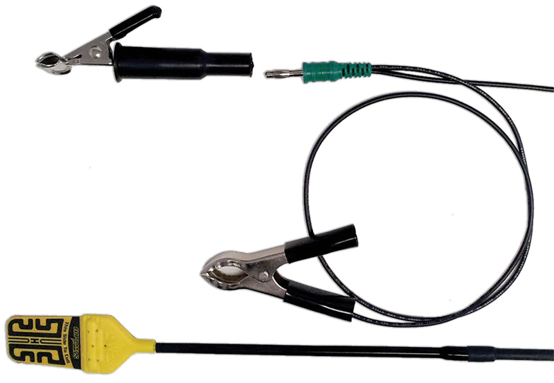
This is one choice and simple to use with any scope. The addition is the clip for systems that use secondary high tension wires. Note however that this is only a pickup and will offer enough detail as to how the COP is operating with ECM control. The choice in this instance was from AESWave and we acquired the BNC version for the scopes in use.
Back to the harness “piggy back†extension and it’s needed NOW!
This should also mean that the COP coil can be removed/rotated and include a secondary wire from the COP to the spark plug. With the clip attachment, would the image look different? Can lean or rich conditions be measured? Is there more detail? What is the difference between the paddle on the COP and clip measurement at the secondary wire? (Clip it close to the spark plug.)
The preferred method is a professional paddle that should guide the learning technician as to how a COP works and is the simplest method by far. Details on the secondary side however, will offer far more valuable information.
The magic wand works but include attenuation 20:1 at the scope side, just to be sure.
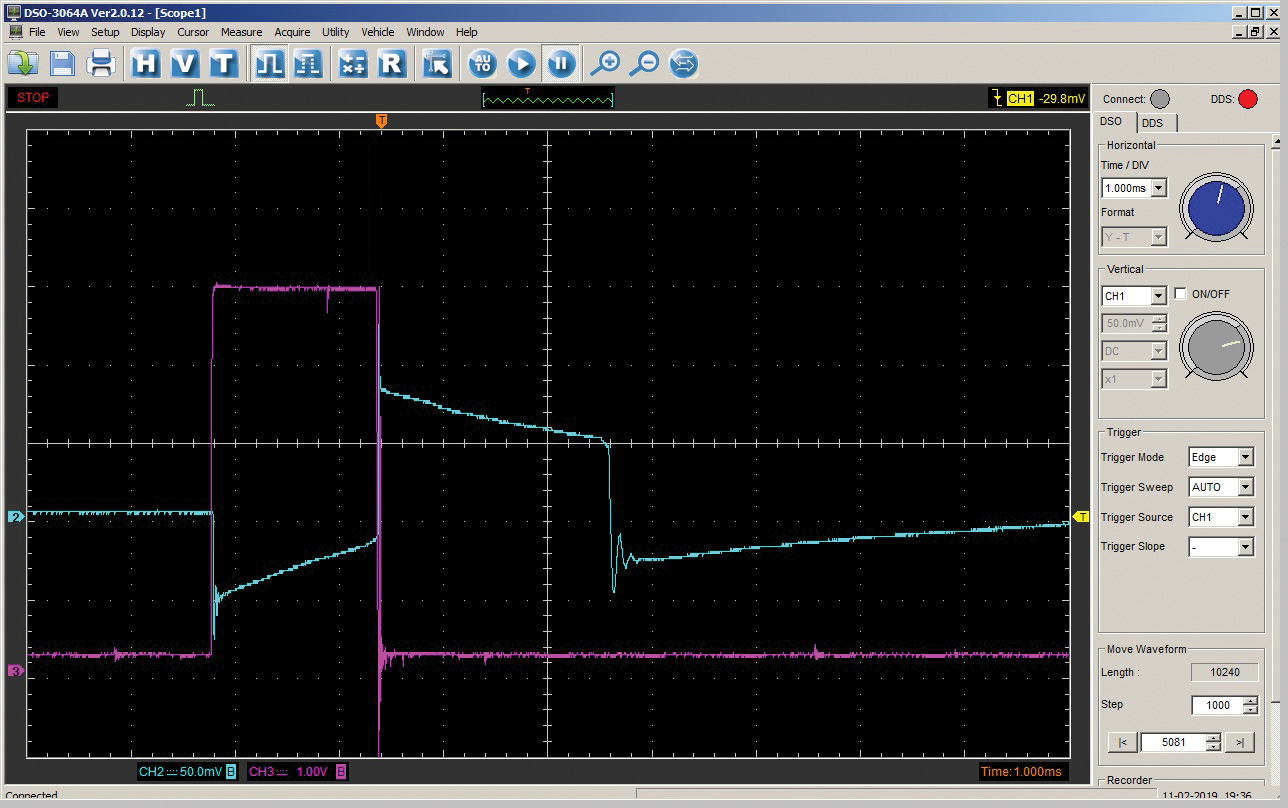
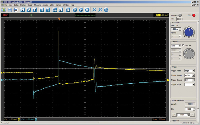
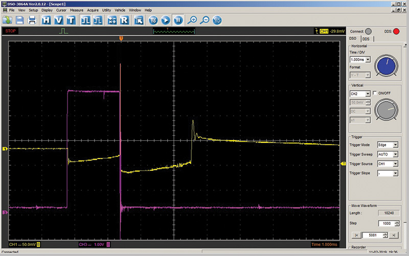
Violet is the ECM input to the coil to trigger a firing event.
Blue is the COP pickup – From the previous article, the ECM input can be measured as the “coil saturation†in ms.
Yellow is the secondary output with a clip.
This is the reason for the breakout harness for the trigger event and with an amp clamp, measure the ramp.
What will the secondary look like with the clip on the secondary wire?
What is the relationship between the ECM input and the secondary output?
What is the relationship between the secondary output and a paddle?
So what is the difference between the paddle and a clip on the secondary wire between the coil and spark plug?

Is there a relationship between the secondary output and the COP with a paddle or magic wand? They both tell the truth, but this is deeper.
Ever wonder what a misfire or oiled intake valve looks like on a direct injected engine? It may be a good idea to measure before and after a cleaning.
As you’ve seen in previous installments of our “magic wand†series, we try to offer creative approaches to automotive diagnostics. You’ll recall that, in previous experiments, wheel speed sensors were used as “magnetic wave sensors†to measure simple ON/OFF solenoids and analyze the COP ignition coil(s). The experiments were tested along side known automotive test tools with an oscilloscope.
With a wheel speed sensor, the reluctor spins at right a right angle to the mounted wheel speed sensor. The edges of the reluctor wheel (in part) create a magnetic waveform that the sensor absorbs over time. The faster the reluctor spins, the greater the attenuation and frequency of each rise and drop of the reluctor teeth across the sensor. Methods of measurement can be RPM via an ABS control unit or oscilloscope signal.
The experiments with the sensors were captured in parallel with an automotive device. I was surprised at how close the various waveforms resembled each other within the test. During the experiments, there was a conscious attempt to apply the cost of each device.
There will be a few more experiments with different sensors that were “scavenged†to measure their properties as opposed to an automotive device. These experiments measure and graph the physical force of a magnetic wave at a solenoid or ignition system.
What about physical forces such as positive or negative pressures? Will these speed sensors offer any type of data that will correlated with the above noted pressures? I think not, but what about using an electrical device to measure a physical pressure in its simplest form? Can a device be re-purposed or created to measure pressures that are very low compared to the very high pressures of a direct injected engine?
The magic wand articles don’t have a specific conclusion except for experimentation with devices and sensors that are re-purposed, or created, for use with a multimeter or oscilloscope. This includes simulation of inputs or outputs of a control unit.
Thoughts and experiments are where an inquisitive mind can test theories and later apply what was learned towards a practical use.
Download PDF


0 Comments