
Normalization solves many power window problems, and is as easy as pressing and holding a button.

Some power window problems are hardware related, solved by repairing or replacing damaged cables or connectors, cleaning or substituting new for corroded components, or lubricating moving parts. In the unlikely event of failure of a computerized control unit, replacement is the solution.
More often than not however, Mercedes-Benz power window issues are simply the result of an interruption of power supply to a window switch, motor or control unit. Automatic functions such as one-touch opening and closing of windows, anti-pinch and other features require the door control unit to determine the current location of the window relative to a stored reference point. Power loss erases stored data that tells the controller where the window is in relation to the desired position.
The driver or passenger may still operate the window manually, but can no longer effectively use one-touch automated functions. Without the correct location data the controller may still operate the power window motor, but one-touch automated actuation may move the window to an unintended spot.
Normalization
When window location data is wiped out the power window motor is said to be denormalized. The solution to denormalization is to help the computer relearn the location of the open and closed positions of the window, and it does not require a wrench or much labor time. You pull or press the window adjustment switch to move the window through its full range of up or down motion, and hold the switch for about a second at its end stop.
This teaches the door control unit the location of the power window’s full open and closed positions, and stores the data as reference points in the door control unit database. The process of setting the reference points for power windows (and other movable components, such as sunroof and seats) is called normalization.
Once the reference points are reset, the window is again normalized. You can perform normalization manually or using the Mercedes-Benz vehicle diagnostic system. Similar procedures apply to normalization of the seats, sunroof and roller blinds, if equipped.
You must perform normalization after any situation that causes the control unit to lose its stored reference point value for the window. Loss of reference point data can occur due to collision impact or other damage to the power window wiring or connectors, or simply from disconnecting the power supply to the circuit.
Hall sensor signals
The window closed position is the reference, or zero point for Mercedes-Benz power side windows. Movement from closed to fully open and back establishes the range of adjustment possible for the window.
Once the reference point value is set, the door control unit determines the actual position of the window using signals from the Hall sensor in the power window motor. Algorithms in the door control unit translate the number and speed of rotations of the power window motor armature into a numerical value for each possible location of the window relative to the closed (reference point) position. This location counter uses the window reference point as its zero value. The location count increases as the window is opening and decreases when it is closing.
When the location counter value exceeds the maximum amount the window can travel when opening, or goes below zero when closing, the control unit interprets the data as an indication that something is wrong. The power window is denormalized and the control unit ceases any automated window functions. Similarly, if the control unit receives no Hall sensor signals when a given power window motor is actuated, it shuts down automated functions for that window. The cause of the fault is stored in the door control unit.
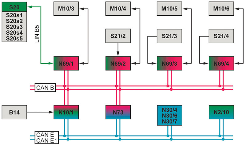
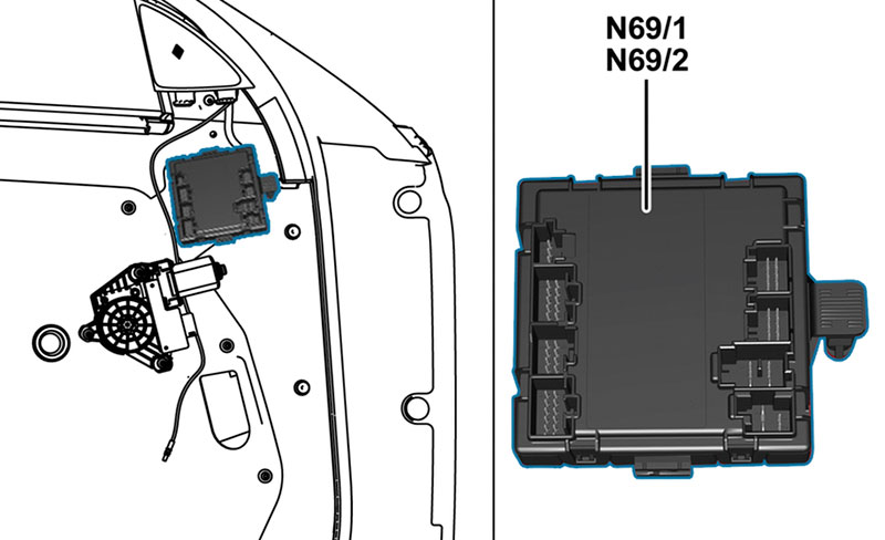
Electric motors raise or lower a mechanical lifter to close or open a power side window. Each motor is connected to a control unit at each door, e.g., the left front (LF) power window motor (M10/3 in the power window circuit diagram above) connects to the LF door control unit (N69/1). The control unit receives signals from a power window switch located in the door panel (S20) and actuates the power motor to raise or lower the window depending on which direction the switch was pushed.
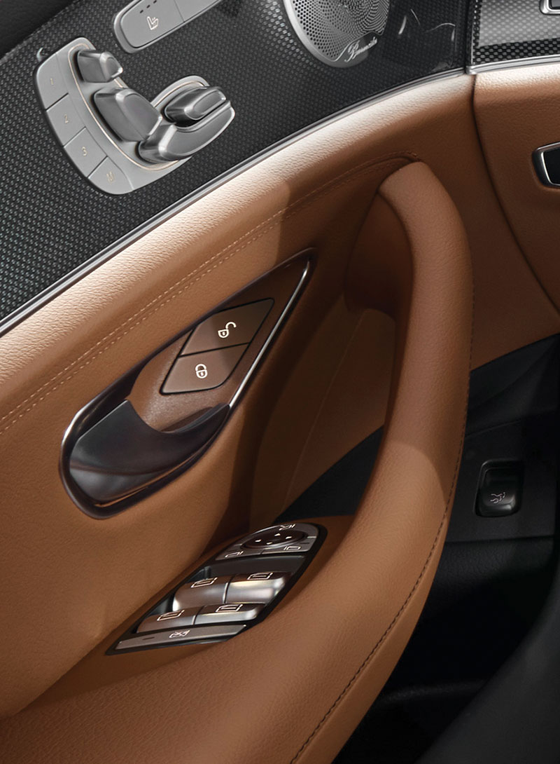
There is an individual power window switch at each door (S20s1, S21/2, S21/3, and S21/4). To allow the driver control of all windows, there are also power window switches for each of the four doors in the driver-side door (power window switch group – S20). The driver’s door controls overrule commands from any of the other door control units. There’s also a rear door cutoff switch (S20s5) that, when actuated, prevents the switches in the rear doors from operating the rear windows, part of the child safety system.
Each door control unit allows manual (hold the switch until the window has moved to the desired position) or automated operation (pull or press the switch for a fraction of a second to actuate automatic operation) of that door’s window. A Convenience feature (for vehicles so equipped) enables actuation of all windows and the sunroof simultaneously.
In the Model 212 E-Class, all door control units connect to the front SAM control unit (N10/1), which includes the fuse and relay module, through CAN cabling (CAN B) that services interior devices. If the power window does not work at all, check the fuse for the appropriate door control unit. If the fuse is ok, check connectors and wiring between the fuse, the relay module, and the power window switches for faults.
A faulty power window switch can cause problems. Using XENTRY Diagnostics simplifies checking the switches, using the Actual Values menu. If you don’t have a XENTRY machine, then check Mercedes-Benz STAR Wiring for the correct input and output voltages at each switch. Note that in some models, the switch may be networked instead of voltage-coded. If the switch is functioning properly, there are other components in the system that may contribute to power window faults.
Door control units interact with control units for the electronic stability program (N30/4, N30/7) and if so equipped, regenerative braking system (N30/6) as well as the SRS control unit (N2/10). The controllers connect to each other through the chassis CAN (CAN E or E1). If the electronic stability program detects an impending impact or rollover event, the ESP control unit, as part of the PRE-SAFE® function, actuates the power window motors to raise the windows to help prevent passenger ejection or injury. Check CAN lines between the power window motor, its switch, and the ESP and regenerative braking control units for wiring or connector damage.
Normalization of the power window motor is quick and easy. It involves raising the window to its end stop, holding the control button for at least three-tenths of a second (300 milliseconds) longer, then releasing it. This sets the location counter to zero for that closed position, and end point normalization is complete. Note that these normalization instructions apply to the 2018 E350 4MATIC. The hold time or other procedural steps may differ for other Mercedes-Benz models or different build years – check the owner’s manual.
Relearn for each automated device

You must set the end or reversal point for each automated component that has become denormalized. Window-related automated features on Mercedes-Benz models include controls for the side windows, sunroof, and roller blinds. Each can become denormalized if damaged or after loss of power, and require a reset (normalization) to restore automated function.
For each component the objective is the same. Move the window, sunroof, or roller blind to its end or reversal point and hold it for the specified amount of time for the control unit to store the location information in its memory. Refer to the vehicle owner’s manual or repair information in the Mercedes-Benz Workshop Information System (WIS) for specific device normalization procedures.
This end point relearn allows the control unit to capture the Hall sensor signal output that represents the exact number and speed of motor armature rotations for each different automated power window position. The control unit stores the data in location counter numeric values. Window movement down increases the count, up decreases it.
Once the controller learns the end point for each automated device, it uses the number and speed of motor armature rotations to determine where the component is in its potential travel range. This allows the technician to set only the end point, and not have to set every location or stop in that device. The controller calculates the number of motor armature rotations and speed necessary to move the window, sunroof, or roller blind to the pre-set location requested by the one-touch (automatic) button or lever.
Signals that appear to be outside the specified range for a given device cause the control unit to cancel automated function of that component. For example, when the rear window roller sun blind is actuated for more than 15 seconds, the sun blind is denormalized. If the voltage of the on-board electrical system is too low, the roller sun blind is also denormalized.
The control unit calculations enable movement to the correct positions for all automated devices. This includes ability to close the sunroof and all windows simultaneously (convenience closing function), full or partial window and sunroof closing when it rains, PRE-SAFE closing in potential collision situations, opening windows for post-crash ventilation, and anti-pinch, which backs the glass a slight distance from a hand or other blockage it detects in its path.
Following are examples from the 2013 E350 4MATIC of automated power component functions that are enabled by normalization.
Rain closing
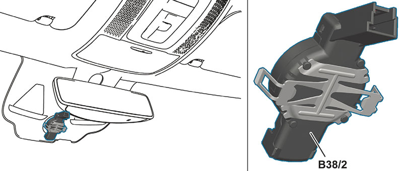
When it rains, the rain/light sensor (B38/2) signals to the door control units to close side windows either completely or until only a small gap remains open. It also sends signals to an open sliding or panoramic sliding sunroof (if so equipped) to close and raise to the tilt position, or if it is a heavy rain, to close completely.
The rain and light sensor assembly includes, among other things, technology to detect the presence of moisture on the windshield.
A transmitter beams infrared light at a specific angle to the exterior of the windshield. When the outside of the windshield is dry, the infrared light is almost completely reflected back to the rain sensor. If there are water droplets outside on the windshield, a portion of the light is diverted. The lower the light intensity received back to the sensor, the higher the degree of wetting it measures on the windshield exterior. Refer to WIS for information on diagnosing rain sensor input and output issues.
PRE-SAFE (if equipped)
When the Mercedes-Benz electronic stability program or regenerative brake system detects a collision or otherwise unstable vehicle status, the ESP or brake control unit requests initiation of PRE-SAFE. Included in PRE-SAFE are commands to the door control units to raise the side windows, to reduce passenger ejection risk and minimize injury. On the E350 4MATIC, this automatically raises the side windows to within 4 mm of the end point (upper stop). Refer to the Mercedes-Benz Workshop Information System (WIS) for application-specific instructions to set and normalize automated power window functions on PRE-SAFE equipped Mercedes-Benz models.
The ESP and regenerative brake system control units transmit their requests for PRE-SAFE window actuation via chassis CAN (for models built up to February 28, 2013), chassis CAN 1 (models built as of March 1, 2013), front SAM control unit, and interior CAN to the front and rear door control units. The front and rear door control units then directly actuate the power window motors. Refer to the wiring diagram to see where to test on PRE-SAFE equipped Mercedes-Benz models whether or not signals are getting transmitted from the chassis CAN or chassis CAN 1, front SAM control unit, and interior CAN to the front and rear door control units.
Crash deflation
Triggering of air bags, seat belt pretensioners, and other pyrotechnical restraint equipment releases smoke particles in the vehicle interior. The side windows then open automatically, creating a slight gap to allow smoke to quickly disperse.
The Supplemental Restraint System (SRS) control unit (N2/10) transmits the collision signal to the front and rear door control units, which then actuate the power window motors. The signals travel to the door control units in the same way as with PRE-SAFE, explained above.
Anti-Pinch Function
Movable components such as the windows, sunroof and roller blind are equipped with an anti-pinch function. This systems helps prevent injury or damage if a window, for example, meets an obstruction while automatically closing, such as if your dog sticks her head out the window at the wrong time.
The control unit monitors the motor speed by examining the pulses from the Hall sensor and, if the motor slows more than a certain threshold, the automatic operation stops and the window (or other device) reverses slightly. However, conditions such as wear and dirt, moisture or ice in the mechanical components can create forces that slightly impede movement.
If these forces are not large enough to engage the anti-pinch function, the movement characteristics are learned and stored in the control unit, to prevent inadvertent triggering of the anti-pinch function.
In severe cases, it may be necessary to clean or adjust the guide rails or window glass to allow for smooth operation. Frameless doors, such as those found in roadsters and convertibles, have several possible adjustments, any of which can cause problems if incorrect. Check WIS for the adjustment possibilities for your specific vehicle. To find any binding points, remove the motor and carefully operate the system by hand.
The motors themselves either contain a thermal fuse, which temporarily disables the motor when it overheats, or the control unit calculates the motor temperature based on operating time. In the latter system, overheating protection is canceled for the reversing action of the anti-pinch feature.
Mercedes-Benz window, sunroof, and roller blind technology is far more sophisticated than that of just a decade ago. But when you understand the system’s operation, use and repair is still as easy as pressing a button.Â


0 Comments