While reading this article, associate this Audi TT DSG transmission with models such as the A3 and various VW models. Be aware that not all DSG transmission controllers display data in the identical fields and groups compared to this TT that was tested and repaired.
History
The vehicle owner asked to have the TT serviced but there was a problem starting the vehicle. The inspection (a service call at the home) revealed a battery that failed. Unfortunately, someone left an interior light switch on and over time, the battery discharged. Charging the battery overnight offered the best solution instead of a tow call. VCDS was used while the battery was charging and recorded multiple faults associated with low battery voltage. For the time being, all faults were deleted.
But the Transmission is Misbehaving
The TT and owner arrived at the facility sometime later. The customer mentioned slow response with shifting engagement in P and R, and also the shift program seemed sluggish, slipping, and somewhat lazy. This was personally noticed when moving the TT into the “Lab†for diagnosis.
| Tools Used | |
| VCDS with a 90 amp power supply | ElsaWin – Using the guides |
| Screen capturing software | Pen and paper with a simple camera |
| Ross-Tech Wiki – Use the guides | |
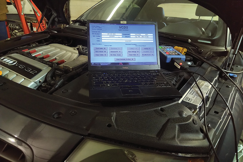
VCDS captured the initial recording when the vehicle arrived. Refer to the recording and listed fault codes as a guide and reference as to how this transmission was tested. Keep all subsequent scans and images to measure a successful repair.
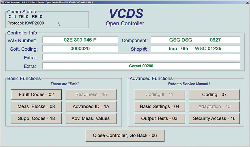
Notice the diagnostic protocol KWP2000. KeyWord Protocol 2000 is identical to ISO 9141 using one underlying physical layer. We would refer to it as the “K†Line. KWP2000 offers bidirectional serial communications and requires specific wake up sequences and is compatible with CAN.
First Recording and Initial Faults
3 faults found:
- 17117 – Gear 3 P0733 – 000 – Incorrect Ratio – Intermittent
- 17119 – Gear 5 P0735 – 000 – Incorrect Ratio – Intermittent
- 19143 – Unexpected / Implausible Mechanical Gear Disengagement
P2711 – 004 – Intermittent
The assumption was that, when the TT was stored, the DSG behaved normally.
With a voltage/power issue and parasitic draw, those adaptations may need to be set up again with VCDS and with a road test.
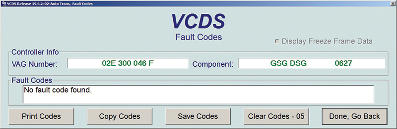
This particular model has an early software level which is also noted in the first image and highlighted in red:
Component: GSG DSG 0627
The early version is under 0800.
To accomplish the Basic Settings procedures, there are prerequisites that must be followed.
The fluid level must be correct via VCDS and monitoring the spill port at the transmission. At group 019, the correct temperature reading is at the DSG controller address 02.
Note
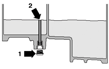
The transmission oil level is correct if a small amount of fluid drips out of the spill port. The engine MUST be running and start with a cold ambient temperature. Remove the plug when the engine is running.
Run the engine and test with VCDS at transmission oil temperature between 35 degrees C and 45 degrees C.
Expect the fluid to spill slightly because heat will expand the fluid.
Remove the plug (1), replace the gasket and wait until the target temperature is achieved. Have extra fluid on hand and ensure a drip tray.
If a fluid change is due with a new filter, capture and measure the old fluid by removing the plastic tube (2). Measure the removed amount, reinsert the tube and inject the measured amount through the spill port.
Attach the plug and run the engine for a few moments and remove the plug again to test the oil level. Top up as required with the correct fluid.
Align the Throttle Body First
- Ensure there a no faults recorded. If any faults exist with the ECM and TCM, repair those faults first.
- Adapt the ECM drive-X-wire throttle in basic settings 060 and 063.
Requirements Continued
Make sure the shifter is in P and the engine is running with the transmission fluid temperature greater than 30 degrees C.
Apply the brake and continue through the entire procedure.
Do not operate the throttle pedal.
Ensure the cruise system is turned off.
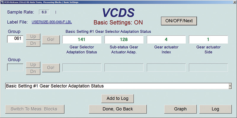
Start the setup in this order and be aware the transmission will make noise. With VCDS and using function 04 Basic Settings, begin with Group 061, wait until Basic Settings switches to ON and all the fields stop changing numbers. Use this following live example for 061.
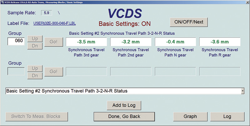
When group 061 is completed, move on to Group 060.
Again wait until Basic Settings has switched to ON and all numbers have stopped moving. Follow this live example for 060.
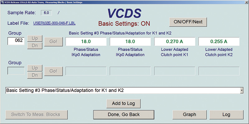
The last procedure is with Group 062.
This procedure may take time to complete but Basic Settings will report ON when completed.
Recheck for faults before the road test and continue if no faults exist.
Next is the Road Test; Follow the Procedure
- Begin in Tiptronic mode from a standstill and up to 6th gear.
- Drive in gears 3 or 5 for approximately 5 minutes.
- Drive in gears 4 or 6 for approximately 5 minutes.
- Maintain the engine speed range for all gears between 1200 and 3500 rpm for clutch calibration.
- Complete one hard braking maneuver followed by a quick full throttle acceleration for a few moments while in Drive and NOT in Tiptronic mode.
- This tests the oil return check.
With VCDS and using the correct label that fits the model, use the basic settings application in the correct steps. If the specific label is not accessible, use the Ross-Tech Wiki guide and follow those instruction to the letter.
Special Note: If for any reason a TT has a newer software version greater than 0800, the Basic Settings procedure is different. In order they are:
| Group 067 | Basic Setting #1 Version => 0800 |
| Group 068 | Basic Setting #2 Version => 0800 |
| Group 065 | Basic Setting #3 Version => 0800 |
| Group 063 | Basic Setting #4 Version => 0800 |
| Group 069 | Basic Setting #5 Version => 0800 if available |
Power or battery interruptions
With any power interruption and if the vehicle remains in that state, the best option if HVAC faults are recorded as in this case =>
1 Fault Found:
01274 – Air Flow Flap Positioning Motor (V71) 41-10 – Blocked or No Voltage – Intermittent
=> be followed with a clean and stable power supply attached (not your grandfather’s buzz box) with KOEO.
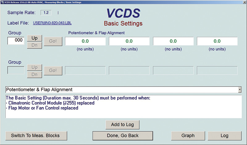
Begin by deleting the fault and, with function 04 Basic Settings, perform the “Potentiometer and Flap Alignment.†Pay attention to the “moving†units (listen for them) that are self aligning. The finished result is offered in the “HVAC reset†image, above.
Exercise the HVAC system at the facility with KOER or with the DSG road test. Recheck and rescan the HVAC system. If the flaps work as intended, no faults should return.
Note: If faults were recognized during the Basic Settings setup, any and all faults will be recorded with a key cycle and/or HVAC exercise.
What needs to be learned
Any and all battery/power faults with these vehicles must include adaptations, Basic Settings and a road test. Adaptations also include electric window “one trip†settings, radio, HVAC and clock/date adjustments, etc.
These procedures may be time consuming but the appreciation goes a very long way when the DSG shifts as intended and the HVAC operates correctly. The appreciation includes the radio presets returning and the correct clock/date adjustment.
Do it right the first time and invoice accordingly.
Download PDF


0 Comments