The ignition coil has been around for over a century supporting spark-ignition engine systems. And while the fundamentals of the ignition coil haven’t changed a whole lot, the approach to diagnosing an ignition problem today has been enhanced by utilizing some of the advanced tools we’ll be talking about in this article. Many of these tools allow us to gain a lot of knowledge on the ignition system’s performance in very short order.
This is good because, with some engine configurations, access to the ignition coil is either difficult or impossible without partial engine disassembly. We’ll be discussing how accessing information about the ignition system’s performance can be carried out fairly efficiently utilizing a few tools and knowledge.
In most cases, a scan tool should be the first angle of attack the diagnostic tech takes when dealing with any misfire-related complaints. Usually a DTC will provide guidance, especially if you have a specific cylinder misfire DTC. However, you may end up with a situation where you have a P0300 code which only lets us know that the ECM has experienced a misfire, or no DTCs at all.
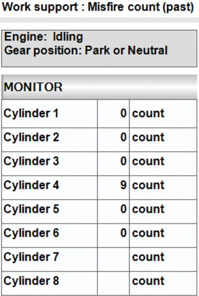
Now if you’re using the factory scan tool CONSULT III Plus, you can enter the Work Support area to look at past misfire counts. For the vehicle being tested, a 2019 Pathfinder 4.0L, the real time misfire option was not supported by this controller. The Work Support could be a useful indicator when looking for clues on vehicles that may have a misfire complaint without a DTC.
There may be times that you suspect that a misfire is being caused by secondary leakage.
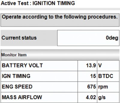
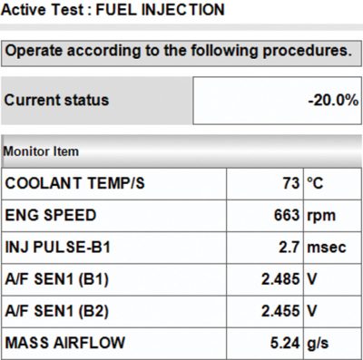
Using bi-directional controls, you may be able to encourage leakage. The closer to TDC spark is commanded, the more secondary voltage will be required to bridge the gap. So if you’re able to command spark closer to TDC and your misfire occurs, then it’s safe to assume that you likely have a secondary leak. Additionally, you can try driving the air-fuel ratio leaner from the Active Test section under FUEL INJECTION to see if the misfire will occur.
Ignition coil basics
Let’s first begin with the basics of an ignition coil. The ignition coil works similarly to a transformer where lower voltage is converted to the much higher voltage needed to fire a spark plug. This is achieved by what is commonly referred to as coil turn ratio. The primary side of the ignition coil will have fewer turns than that of the secondary side which resides within the primary turns. The ratio is likely more than 100:1, meaning that for every single turn of the primary there are 100 turns in the secondary circuit. This is how the voltage is multiplied. A higher turn ratio results in high step-up voltage levels. It’s not uncommon to see an ignition coil capable of producing 60,000 volts.
Using the oscilloscope with a current probe
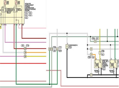
When you reach the point where you want to have a closer look at what might be causing a misfire, you’re likely going to want to assess the ignition system. And if you take some time and study the engine controls wiring diagram, you can develop a strategy that will help you with that mission. After some analysis, you can see that we have a couple of access options we can use to gather the current patterns for all the coils from a single connection.
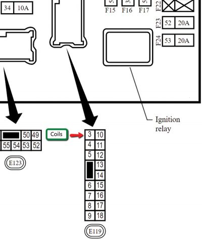
One, it appears that the easiest would be to install a fused jumper at fuse #24 within the Intelligent Power Distribution Module Engine Room (IPDM E/R), located at the right rear of the engine compartment. Now you might ask, how did we arrive at fuse 24? Well, when you look at the diagram, the number 53 is next to the fuse. In order to find out what fuse number that is, you’ll need to look at the IPDM schematic.
However, this fuse also supplies current for other loads such as the camshaft timing control solenoids. Ideally, it’s preferred to sample the circuit that only carries current for the devices under test.
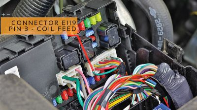
Looking closer at the wiring diagram for the ignition coil power supply circuit, Pin 3 is a green wire that supplies power to all of the ignition coils, and the only other device on that circuit is the EVAP Vent Solenoid (not shown) which we can live with. Looking at the IPDM Breakout, we can see that Pin 3 resides within connector E119 of the IPDM and would serve as an excellent access point for sampling the current signal.
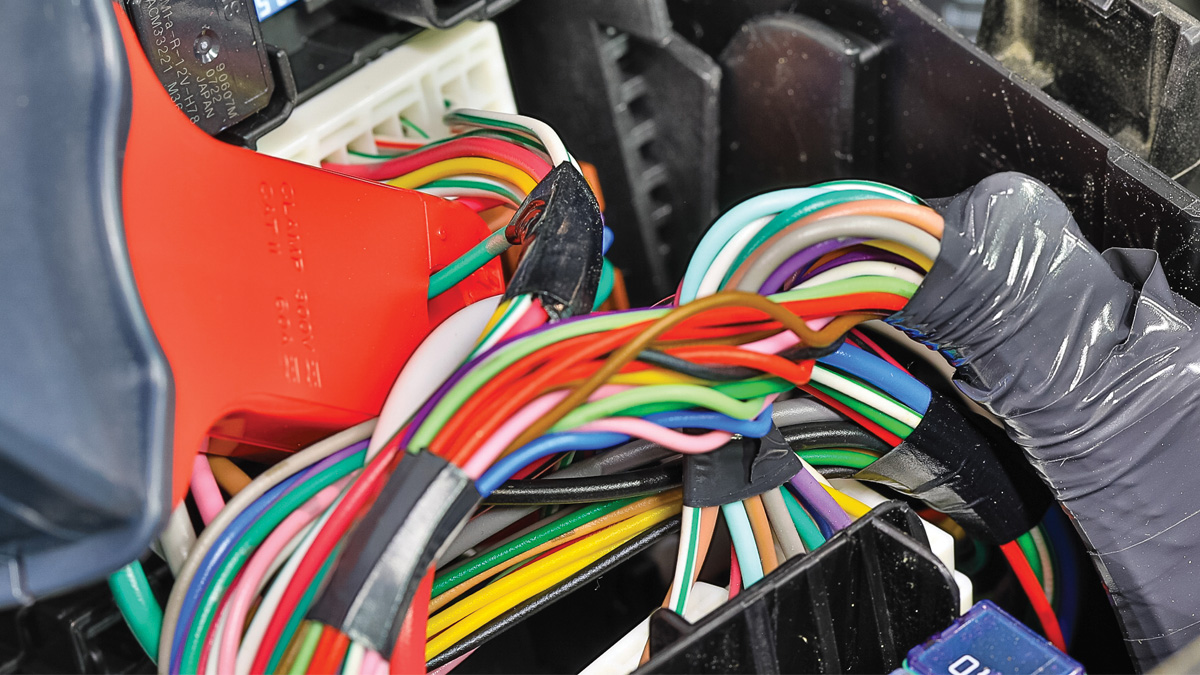
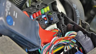
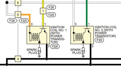
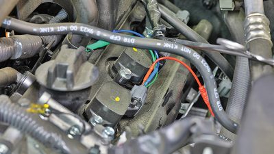
Since we now know where Pin 3 sits, we located the IPDM E/R at the right rear of the engine compartment. After removing the cover, the images of the IPDM connections show what we were presented with. This was a pleasant surprise because attaching a current probe around the green wire is quite simple. The coil diagram for cylinders 1 and 2 shows how we connected the current probe. (Note: with the probe in this position, the current patterns were inverted. Flipping the probe over solved that problem.)
Looking further over the circuits for one of the ignition coils, you can break the circuit down into fundamental basics. For this system we have three wires consisting of the following circuits:
- Power supply – Pin 3
- Ground lead – Pin 2
- Control signal – Pin 1
This system uses an internal power transistor mounted inside the coil to handle the primary current switching. What this means is that we do not have the ability to sample the actual ignition coil primary circuit control signal voltage. Now, if we’re going to access a system that allowed direct access to the coil primary control side, one would need to check the scope specifications to make sure that it would be able to safely handle the high voltage levels this system produces when the coil primary circuit collapses.
In most cases, you’re going to need to use an attenuator which limits the amount of voltage reaching the scope. And if you’re using an attenuator, you’ll want to make sure that the scope is aware of this device so that the measurements displayed on the scope match. Since this is not the case with our vehicle, we don’t need to worry about this.
Nevertheless, we’ll need to have access to a reference signal so that we can assign each coil current ramp to its respective cylinders. It doesn’t matter which cylinder we connect to as long as we know which cylinder it is and what the firing order is. For this vehicle we decided to reference the #2 cylinder because it was the easiest to get to.
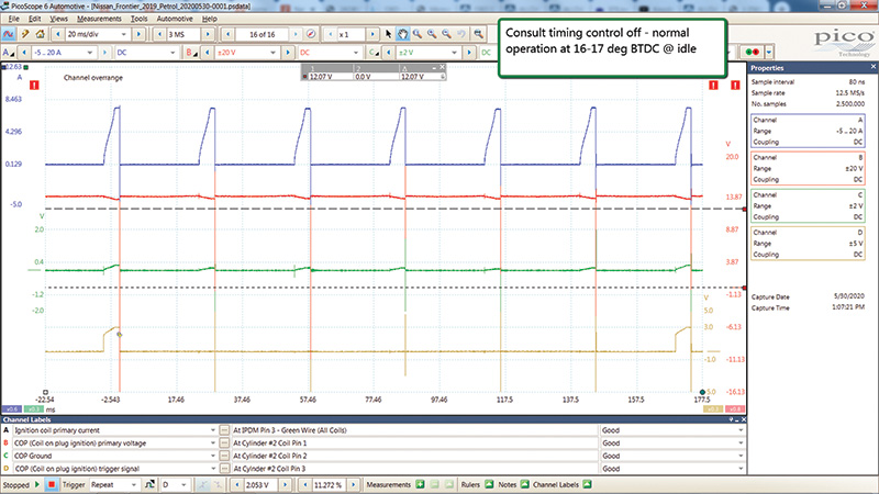
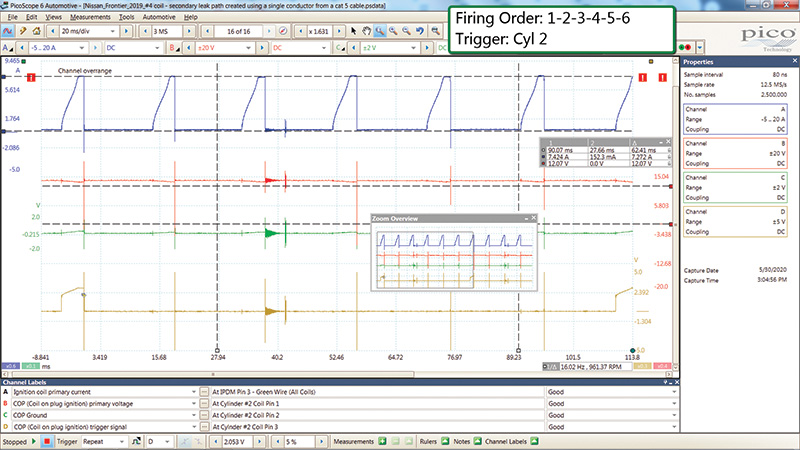
For a complete analysis of all the coil circuits, we’ll address this circuit as follows: (Note: colors are referencing the scope traces and not the back pin probes.) Channel A (blue) is used to sample the coil primary power supply mentioned above. The next lead from Channel B (red) of the scope is connected to the coil #2 power supply at Pin 3. Channel C (green) is connected to coil #2’s Pin 2 which is the coil ground. And finally, Channel D (yellow) is connected to the coil control circuit at Pin 1 and, as mentioned earlier, this will be our reference signal so we know which coil events belong to which cylinder.
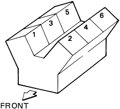
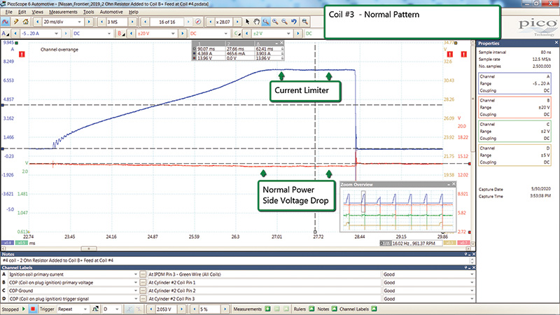
Since the vehicle we’re working on is a 6 cylinder V design with a firing order of 1-2-3-4-5-6, and triggering on cylinder #2, the firing order sequence shown on the pattern is 2-3-4-5-6-1. The PicoScope image shows a normal pattern at idle.
For the purpose of this article, cylinder #4 was selected for coil-related bugs. Coil #4 is right next to Coil #2. For verification, service information confirms this as shown in the PicoScope image above.
So, let’s take a deep dive and break down the waveform patterns. The areas to look at are as follows:
- Peak coil current and/or current limiting. This circuit is reaching just over 7 amps before current limiting takes over. Note: you’ll also see that there is a normal amount of voltage drop indicated on Channel B when current is flowing.
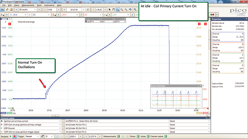
- Coil transistor saturation turn-on. This area you’ll want to zoom in on and take a look at the oscillations that occur upon the initial primary current circuit current flow. Compare this to the other cylinders to make sure that they’re all similar.
A defective coil will typically be missing these coil oscillations. - Coil Primary Circuit Collapse. This is the point at which the primary current stops flowing and the ignition coil secondary circuit delivers a high voltage charge to the spark plug. You can see that this high voltage is being generated and is being shown in all of the waveforms we’re sampling as shown back in the PicoScope pattern. This is important to know because you may have a coil that is unable to deliver a spark across the plug and this setup may be able to help provide you with more intel when you’re investigating a driveability complaint.
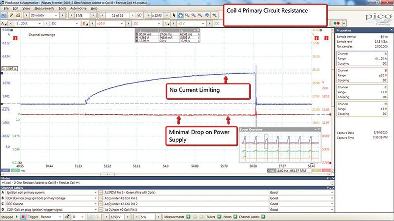
If one of your coil patterns is not reaching the current limiter, then this is an indication of high primary circuit resistance. A normal system should have the coils all be fairly equal. If you have any of them that are out of the ordinary, then you want to do a little more investigation. If the current is low, think about what could cause that. The likely cause is high resistance in the primary circuit, so that could be internal or external to the ignition coil.
For the purpose of research, we placed a 2 ohm resistor in between the #4 coil Pin 3 and power feed. This pattern shows the results where the primary circuit is only reaching 3.9 amps. This is 3 amps less than that of a normal system. If you look closely at the Zoom Overview, the third current ramp event for cylinder number 4 is lower than the others.
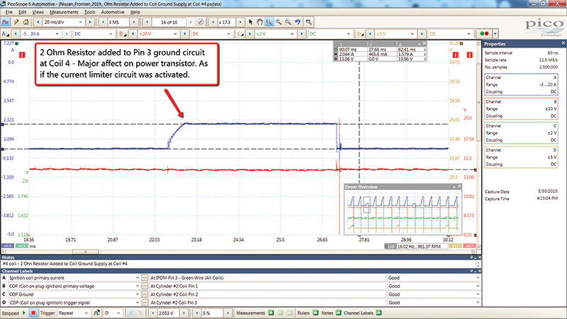
Next, we decided to move the same 2 ohm resistor over to Pin #2, (coil ground) and see the results. Looking at the next figure you can see that, although the current level never reached the current limiting levels that the normal system achieved, it’s clear that the internal coil circuit entered current limiting mode.
Next, we created a secondary voltage leak path for cylinder 4. As you can see, there is a clear indication that something is wrong following the coil firing event for this cylinder. After seeing several of these patterns in the real world, we know that this is how a secondary voltage leak outside of the cylinder looks.
Conclusion
The ignition systems utilizing Coil-Over-Plug (COP) technology are quite robust but, when problems arise, a scan tool, oscilloscope, and service information can be leveraged to help the service technician gain valuable intel when addressing ignition system complaints.
Download PDF


0 Comments