
When Porsche discontinued the air-cooled 911, it simultaneously launched its new entry level car: the mid-engine, water-cooled Boxster. The departure from Porsche’s air-cooled platform, which had always been Porsche’s hallmark, was controversial at best. Air-cooled engines had become expensive to build and it had become more difficult to pass stringent emissions regulations using an air-cooled engine.
The early air-cooled Porsches were more of a no holds barred, damn the expenses, offering. However, with rising competition producing relatively inexpensive, high performing sports cars, it was clear that Porsche had to lure customers with something a bit more affordable. It might even be suggested that a whole new platform would be required (that being the mid-engined, water-cooled Boxster) to allow Porsche to distance itself from its iconic air-cooled power.
The choice of a six cylinder, horizontally opposed layout was almost a given as it provides two important advantages in a sports car — a lower center of gravity, and the fact that a flat engine fits neatly into a low profile, sleek body design. Aside from the basic architecture of the engine itself, many considerations relating to the cost of production had to be weighed in order to fulfill the need for an entry level offering.
There are more similarities than differences between the M96 and M97 engines. There are several different evolutions of displacement altered by increases in bore and stroke, but the easiest identifier between the M96 and M97 is noting whether it is equipped with VarioCam or VarioCam Plus. The earlier M96 engines came equipped with VarioCam, while the later, improved M97 engines received the VarioCam Plus feature. The more nuanced differences between the two different valve timing strategies are discussed later in this article.
The expensive dry sump oil system found in the earlier air-cooled 911s, and a bit later in the high end 996 Turbo, GT2, and GT3 models, was gone from the new design. By designing what Porsche refers to as an “integrated dry sump,†manufacturing costs were trimmed because external oil lines and tanks were not necessary.
The M96/97 engine utilizes a traditional gear type oil pump that is driven off the end of an intermediate shaft through a hex key. The term “integrated dry sump†is a bit of an oxymoron when referring to the M96/97 oil system. The traditional definition of a “dry sump†system means that the oil suctioned by the pump is in a remote location and of a significantly large quantity so starvation of the oil pump pickup is all but impossible. The M96/97 engine lubrication system justifies the integrated dry sump design by giving the oil sump, now cast as part of the engine case, robust baffling to keep some degree of oil separation from the high stress components that live directly above it.
To purists and students of the dry sump, air-cooled 911 architecture, this design is nothing more than a well baffled wet sump engine. By stretching the definition of a dry sump lubrication system, Porsche appears to be placating its customer base who might be put off by the new engine design.
To be fair, the design of this lubrication system does a good job of preventing aeration of the oil at the point of pickup. It is eminently vital for a car that is capable of generating high G forces during cornering to allow the lubrication system to function reliably, so oil pickup issues are not an area for compromise.
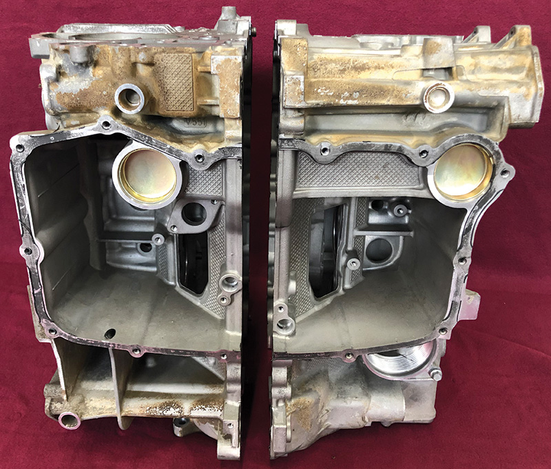
Many other changes appear to have been made with concerns toward manufacturing economies. One of the biggest departures from earlier Porsche designed engines is the way that the crankshaft is supported. Most of the previously designed engines used the case to provide the main bearing saddles, so that the case itself was a major, stressed component. This design, incorporating the structure to support a crankshaft, was expensive to build both in terms of pressure casting methods and the alloys required.
The new approach for the M96 engine houses the crankshaft in a separate box within the engine case. This housing, or box, for the crankshaft is reinforced with steel inserts at the main bearing saddles, adding strength where the crankshaft is supported.
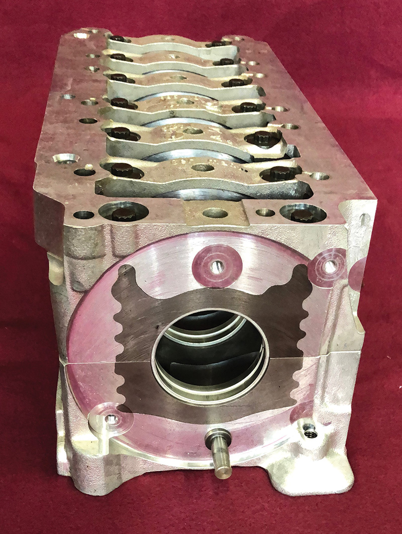
The crankshaft itself has seven main journals with conventional plain bearings. Crankshaft end play is controlled by a typical thrust bearing. The earlier designed air-cooled engines sandwiched the cylinders and heads with long studs that threaded directly into the engine case. Instead, the M96/97 engine has head bolts that run through the case and thread directly into the reinforced crankshaft housing/box assembly. This creative design eliminates the problems air-cooled engines had with the stress on the cylinder head studs pulling them out of the case itself.
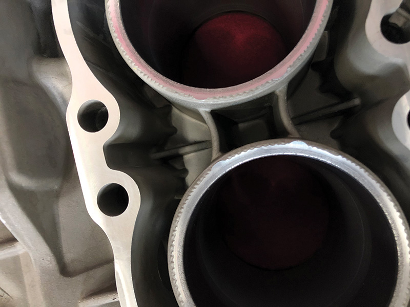
The cylinders for the M96/97 are made from a high silicon liner that utilized a relatively new process by Kolbenschmidt called “Lokasil.†During the pressure casting process the Lokasil cylinder liners are first held in place, then actually become a part of the lower silicon content aluminum alloy used for the larger part of the case.

This process, unique when it was contemporary, reduced production costs while providing a reliable low friction surface for the pistons and rings to ride on. The earliest of the engine cases that were produced did suffer from some quality control issues which were later remedied. With this unique design the engine case surrounded internals almost like an exoskeleton.
The dual overhead cam design of the M96/97 engine requires three chains in order to drive two camshafts on top of each of the cylinder heads.
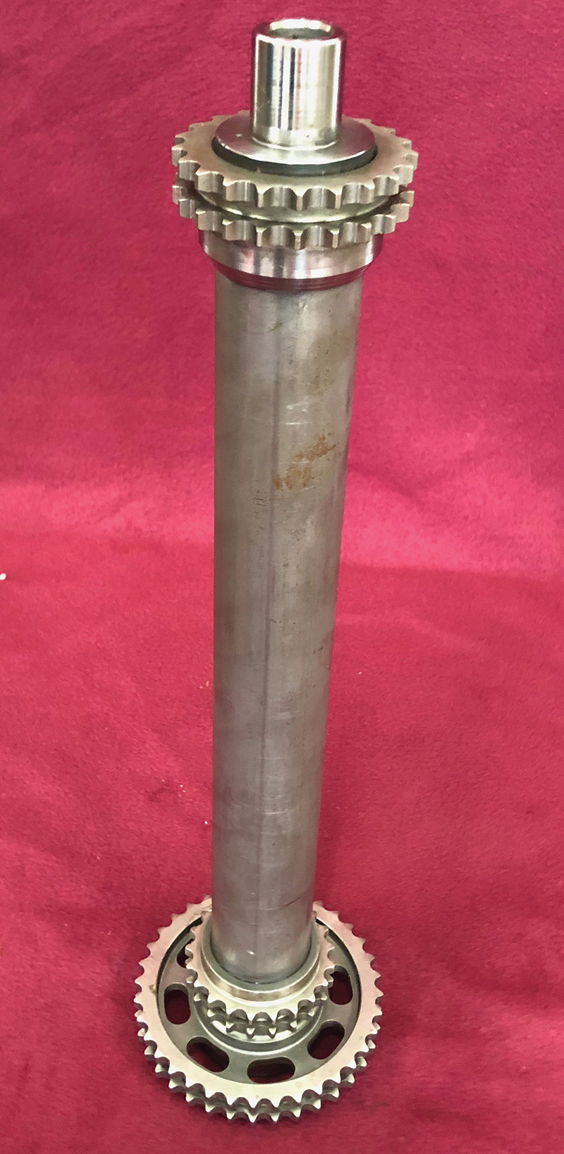
A long, hollow intermediate shaft, approximately the length of the crankshaft and situated below the crankshaft, is first driven by a short, very stout, link style chain, sometimes called a “silent chain.†The intermediate shaft then has a much longer, double-row roller chain at each end, one for each set of camshafts, which are positioned on top of each cylinder head.
Running a cam chain on each end of the intermediate shaft allowed for the use of the same cylinder head on each side of the engine as the cam drive to the cylinder head effectively switches ends when placed on either side of the horizontally opposed engine. Any time one part number, especially for a large and complex casting like a cylinder head, can be used for two applications, cost savings are significant.
Tension on all three of the chains is kept at an even level, each chain having its own tensioner and tensioning ramp. A unique and somewhat quirky design has the intermediate shaft supported at each end by two different bearings — the one at the “front†of the engine being supported by a typical plain bearing, while the rear of the shaft is supported by a sealed ball bearing.
It is important to note that the front and rear of the engine may not be relative to its actual position in the vehicle, as it was used in both the rear mounted position of the 911, and then turned around 180 degrees when it was used in the Boxster and Cayman applications. More discussion of the intermediate shaft ball bearing and its tendency for problems will be discussed in a separate article.
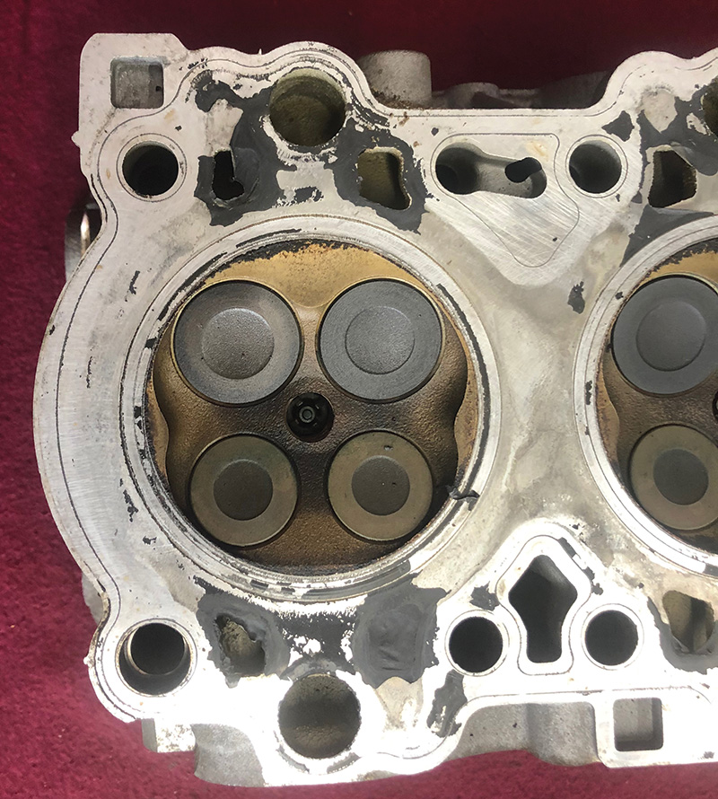
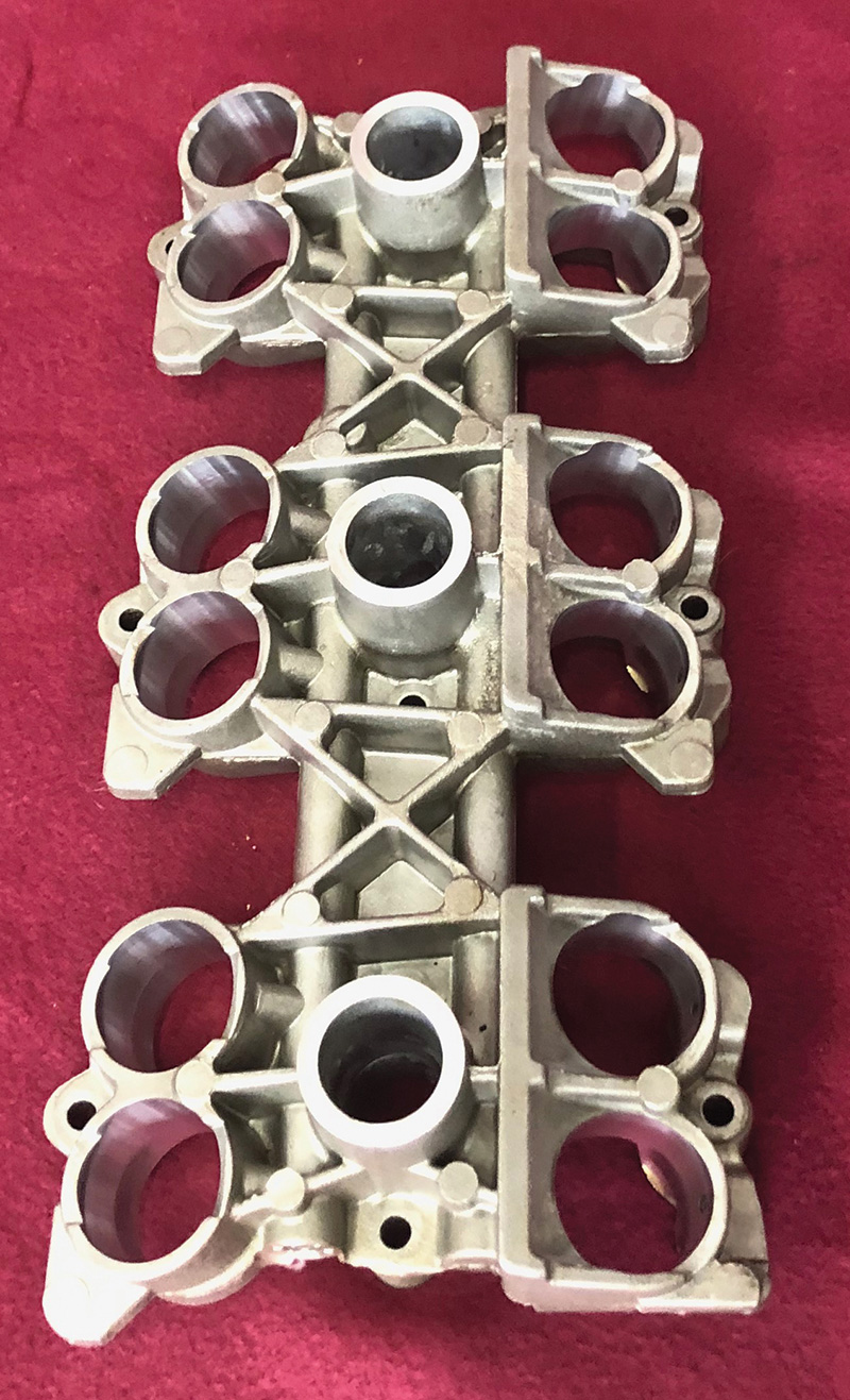
Each head accommodates one intake and one exhaust camshaft that ride directly in the machined bearing saddles of the aluminum castings. The head design uses four valves — two intake and two exhaust — per combustion chamber. Spark plug location is directly in the center of the four valves which is ideal for performance, while also providing a low tendency for detonation as well as low emissions.
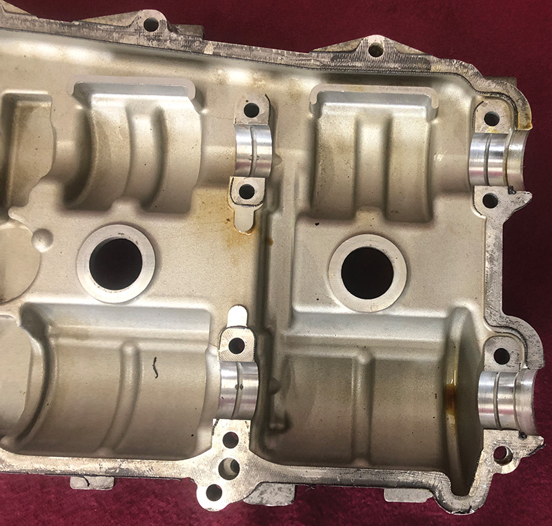
Using the valve cover in this way provides more cost reduction, since individual bearing caps do not need to be cast, bolted to the head, and then line bored during production. Because of this design, special tools are required to secure the cams to the heads during installation of the cover.
There is no gasket used between the cam cover and head, as this would not permit the accurate assembly necessary for the camshaft bearing bores. A special RTV compound is sold by Porsche to create an oil seal between the cylinder head cam cover assemblies. The cylinder heads and covers are a matched set due to the necessity of machining the precision bearing bores with the cover in place. Matching numbers are provided on each head and its respective cover so they can be identified as a set and not mixed up.
There are two designs allowing for variable valve timing as well as variable intake valve lift of the M96/97 engines, called VarioCam and VarioCam Plus respectively. The early design, VarioCam, simply used a cam timing adjuster on the intake camshaft. When certain criteria were met, including rpm, oil temperature, and throttle position, the engine’s control unit would advance the timing of the intake camshaft. This was done through the actuation of a solenoid which, when commanded, would direct oil pressure to the previously mentioned adjuster mounted on the end of the intake camshaft. This was basically an on/off event. The advancement of the cam timing was not linear.
VarioCam Plus incorporates a twist on the original design by altering intake valve lift in addition to the timing of the camshaft. The intake camshaft design has three lobes for each valve instead of a single lobe used in a typical design. The single, inner lobe provides low lift at idle and low rpm, while the two identical and rather narrow outer lobes provide higher lift at higher engine rpm.
A very ingenious two stage intake valve lifter was the key to this technology. Depending on rpm, throttle position, and oil temperature, the inner or outer portion of the lifter will receive oil under pressure which will effectively “select†which cam lobe is to be utilized. The engine control unit activates a solenoid directing oil pressure to achieve this low or high lift event.
The lifters live in a special housing which has the necessary passages to direct the oil to either the inner or outer part of the lifter.
Rotation of these lifters is prevented as well by a small pin embedded into the side of the lifter, which then is guided by a slot in the lifter housing. Preventing the lifter from rotating is necessary as the top of the lifter is curved to accommodate the unique design of the cam as well as the need for correct alignment with the oil passages to the lifter itself.

Adjusting the cam timing on these engines requires a kit of specialized tools that secure the engine on top dead center. Then other fixtures index the cams in their base setting. Slotted holes on the exhaust cam sprocket allow for accurate adjustment of the exhaust cam relative to the intake cam and crankshaft.
It is essential to follow the procedure precisely in order to have the valve timing in its exact base setting. Failure to do so can result in engine damage if it is severely far off, or in setting a Check Engine light if it is only marginally off. The fuel management system monitors the camshaft-to-crankshaft correlation and will flag a Check Engine light if things are not just so.
Throughout the engine there are many torque-to-yield bolts used at critical applications. Among these the crankshaft housing bolts, connecting rod bolts, and the cylinder head bolts are among the most critical.
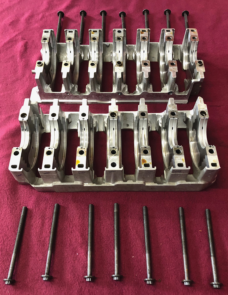
These are all considered to be single use bolts and must be replaced any time they have been installed and torqued using the manufacturer’s specification. The design of a torque-to-yield fastener is that it reaches its desired clamping force by allowing the material to stretch, or “yield†as it is tightened. It is easy to imagine how overstretching something as critical as any one of the aforementioned bolts could wind up with it breaking and catastrophic results.
The M96/97 engine, while innovative in its time, became relatively controversial throughout its use in the 911, Boxster, and Cayman models. A subsequent article will identify and address some of the challenges these engines faced, what repairs were required, and how Porsche, its customers, and service personnel have dealt with the issues.
Download PDF


0 Comments