
Understanding what the Star Wiring diagrams have to offer is key to any successful diagnosis and repair. In this article, we will dive deep into all that Mercedes-Benz offers in this valuable tool.
Star Wiring shows the wiring and electrical function diagrams for vehicles since about 1994, with some information on selected earlier models. Although nearly the same information appears in the Mercedes-Benz Workshop Information System (WIS), Star Wiring offers a unique and convenient user interface, called WebETM, that makes using this information easier. WebETM is more than an an electrical troubleshooting manual, going far beyond simple wiring diagrams. Additional information provided includes function diagrams, component locations, connector pin-outs and basic diagnostic information.
Access to Star Wiring is included with your STAR TekInfo subscription. Visit startekinfo.com to learn more about what is offered and to subscribe. XENTRY Diagnosis owners receive access to Star TekInfo as part of their data package. Once you have logged in to STAR TekInfo, click on the link to Star Wiring on the home page.
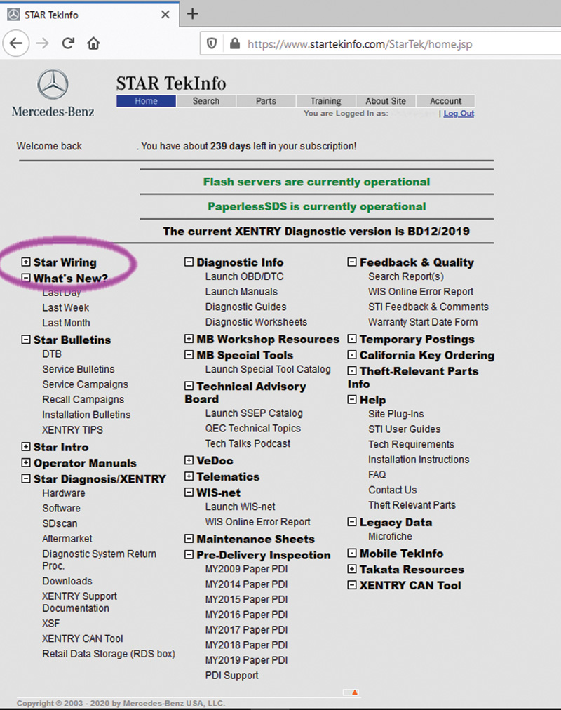
If you are a first-time user of Star Wiring, there is a free plug-in known as Autodesk Design Review that you’ll need to view the wiring diagrams. You’ll be prompted to install it if necessary, but you can manually install it too: On the top tab “About Site,†click on Installation Instructions and pick the link for Autodesk Design Review 2010. On the Autodesk site, search for Design Review: One of the top results explains where to download the free Autodesk Design Review Software. Note that you don’t need the DWF Viewer option.
On the Star Wiring search page, enter the three-digit chassis designation for the vehicle of interest and click “Search.†You can also leave this blank for searching, but this will bring up the WebETM links for about 50 different chassis designations. Handy if you want to browse what’s available, but it could be a bit of a time-waster.
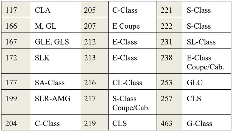
Note that some WebETM entries cover more than one chassis: In some cases, the basic chassis are almost identical so there is no need for a separate set of diagrams. A good example is the Model 117, X156 and 242 (CLA, GLA and B-Class, respectively) WebETM, which all three chassis share. Also note that some chassis have model year breaks, for example chassis 166 has a choice between “up to MY 15†and “as of MY 16.†Always be sure to pick the correct one, since you’ll get the wrong information by choosing the wrong WebETM.
After searching for your selected chassis, you will have a choice: WebETM with STAR Finder, or just STAR Finder alone. In nearly all cases, you should select WebETM with STAR Finder, since this choice offers both the WebETM information and STAR Finder.

STAR Finder
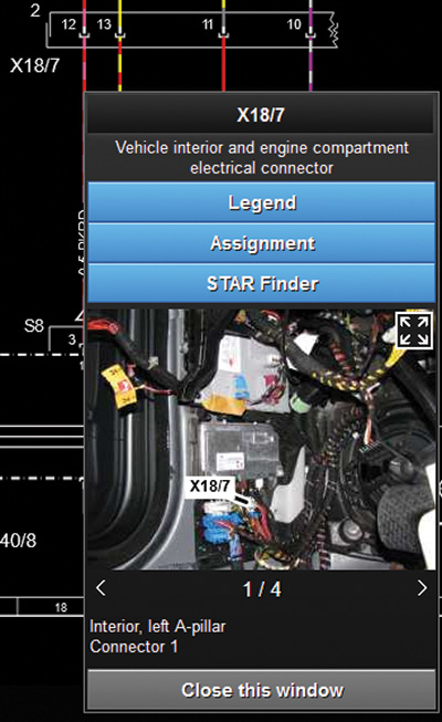
What is STAR Finder? It is a small application that has a simple purpose: To show you where an electrical component is located on the vehicle. Just click the component designation and pop-up window showing the component appears. Images can be enlarged, and more than one image for a component is frequently available.
Today we’ll be using the “Pre-Facelift†Star Wiring for the 205 Model, which includes C-Class vehicles from model year 2015 to model year 2018 for the examples in this article. With very few exceptions, the basic format and operation of WebETM is exactly the same for every model listed.
After selecting the link to your desired WebETM with STAR Finder, a warning screen may remind you that certain models have high-voltage systems, meaning higher than 60-volts DC and/or 48-volts AC. Voltages like this can injure or kill you if you come into contact. Please read and follow the safety notes before proceeding.
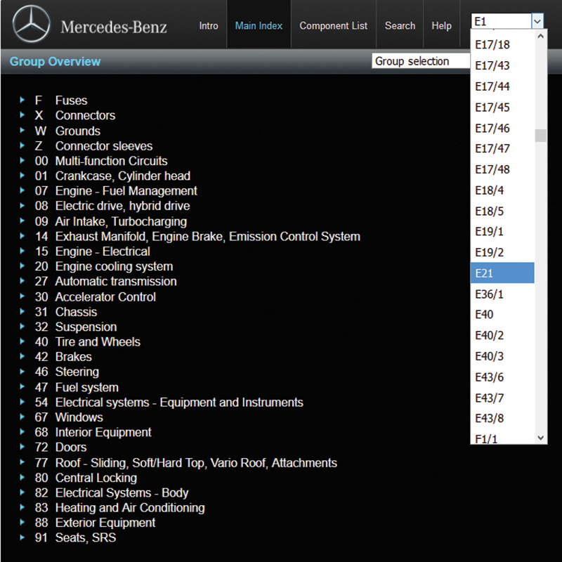
WebETM opens to the main index screen, showing all the service groups and two drop-down selection windows at the top right. The lower one, titled “Group selection,†is just that: A way of selecting the service group by using a drop-down menu. This gives the same results as clicking one of the service groups listed on the left, but is included as a convenience.
Component search

The upper, smaller box is used to find all wiring diagrams that show a specific electrical component. To use this, you’ll have to already know the component designation. For example, the main starter battery always has component designation G1, and the gasoline engine control unit almost always N3/10. The nearby chart shows common electrical component designation letters. Get to know what these letters mean, as this knowledge will greatly assist you when working with a wiring or function diagram.
If you know the designation of a component you need to work on, open the box and type the first letter of the component. This brings you right to that section of the drop-down, and saves the effort of having to scroll all the way down from A1 to your component.
If, instead, we start by selecting a group — Group 32 Suspension for example — a page opens to show all the diagrams available. Note that two kinds of diagrams are listed: Wiring and Function. These serve two completely different purposes.
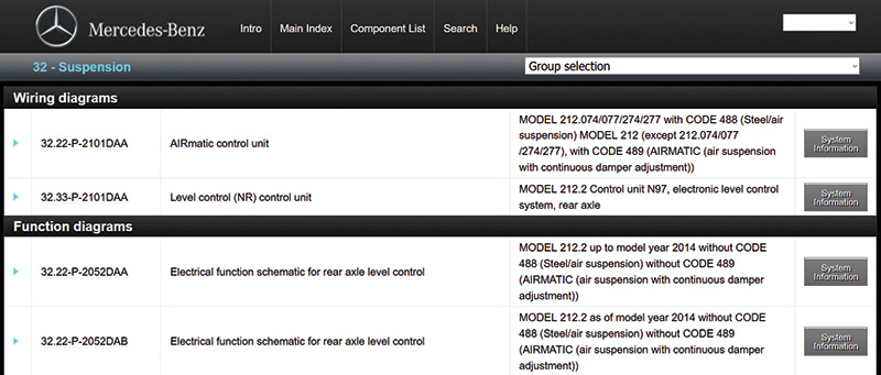
A wiring diagram shows the wire connections between components. If we want to trace the wiring, measure a specific signal, or identify the ground point for a specific control unit or component. In other words, if we want information about the Physical Layer of the electrical system — we turn to the wiring diagram.
An Electrical Function Schematic shows the signal flow between components, particularly on in-vehicle networks such as CAN. If we want to understand how a system works, from where a particular signal originates, or which signals are carried on a CAN Bus — in other words, we want information on how a system operates – we turn to the Electrical Function Schematic.
Wiring diagrams are intuitive and generally understandable, but function diagrams need some explanation. Before networking entered the automotive world, each signal had its own wire. Today, networks can carry multiple signals, and a way was needed to show which signals went where. For example, how could you figure out how the outside temperature reading is delivered to the air conditioning control unit? Sure, you can guess it comes in on the CAN Bus, but from where? The function diagram spells this out.
While you might not always need a function diagram, when networking is involved, the signal flow it shows does make it a lot easier to trace out the concern. Note that function diagrams generally have “jump links†to the relevant wiring diagram for a given component.
Wiring diagrams
Now that you have the basics, let’s dive deeper into wiring diagrams. As we mentioned before, these are schematic diagrams of the physical wiring in the vehicle. By schematic, we mean that they are not drawn to scale, and you cannot infer the installation location or position from these drawings. All you can see is the electrical connections between two components. These components are anything that isn’t a wire: Control units, connectors, fuse boxes, solder splices, and so on.
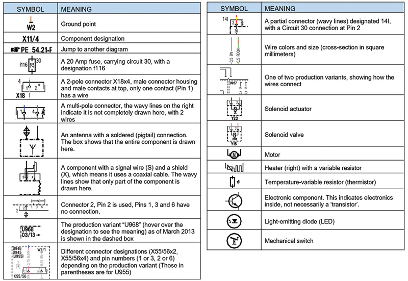
Symbols
To really understand these diagrams, we need to understand the many symbols used. The near-by chart shows examples of some common symbols used on a wiring diagram. Probably the most important symbols are wire, connector and component symbols, but in the end all of these symbols are important in their own way. We recommend studying these components and explanations to get the most from WebETM.
It’s important to mention two points: First, every diagram has a grid frame, used in the Legend to identify a component’s place in the diagram. (The legend lists every component in a diagram and its grid location.) Second, each diagram has a unique number, like PE83.70-P-2101-97DAA (which is the same in both Star Wiring and the Mercedes-Benz Workshop Information System, WIS). Always use the full diagram number to unambiguously identify a specific diagram.
Viewing options
In the brake light system function diagram image (right), you can see a vertical line of controls at the left side of the page. These are used to adjust your viewing options. If you hover the mouse pointer over each one, a description of the control will pop up. While panning and zooming the image are better done with a scroll mouse, the other controls let you print, invert the background color (default is a black background, easier on the eyes) and a control to highlight every clickable hotspot on the page (and there are many — every component designation at the very least).
An example
Lets try a simple diagnosis exercise. You can follow along on the nearby image showing the function diagram of the brake light system. In a 2014 E-Class, Model 212, we have a center brake light (E21) that won’t switch on. Our first guess was to look at the wiring diagrams in group 82 for exterior lights, but all four diagrams state that they are for E1 and E2, which are the headlights — none of them are for E3 and E4, the tail lights. From here, we can either search for E3 (for example), or check the function diagrams. Deciding to check for a relevant function diagram, we find one titled “Brake light actuation, as of MY 14†that is exactly relevant.
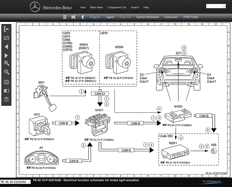
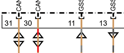
On the diagram, we see that the status of S9/1 (Brake Light Switch) is read in on a dedicated wire by the ESP control unit. The ESP control unit sends a message over CAN E1 to the Front SAM (N10/1). The Front SAM then sends a message via CAN B to N10/2, the Rear SAM. At the same time, the ESP control unit sends a message over a dedicated wire to N10/2, a redundant signal for this safety-critical function. The Rear SAM uses individual wires to switch the various tail lamp bulbs (or LEDs in this case) ON.
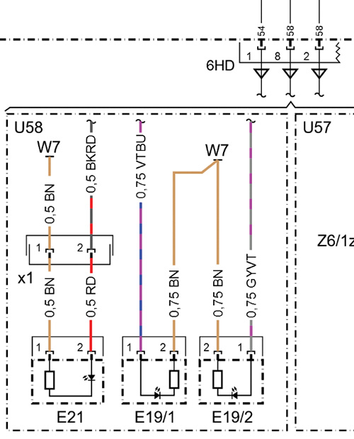
We then follow the jump-link in the function diagram to the Rear SAM wiring diagram, where we see that rear SAM connector N10/2x6HD pin 1 is where the 0.5mm2 black/red wire goes to E21x1 pin 2, the center stop lamp connector. Pin 1 of that connector goes to W7, the right rear wheel well ground point, which was found corroded from a bottle of soda that had spilled months ago. The ground was cleaned up and coated with some protection wax, and the problem cured.
While this is a trivial example — in reality the DTCs in N10/2 pointed to an open circuit in E21 — it shows how the function diagram and the wiring diagram work together to help you better understand the flow of the circuit. Indeed, if we have a look in the Legend (a list of all components and where they appear in the diagram) we can also find the ESP control unit, showing us that the discrete wire from the ESP control unit is a 0.5 mm2 black/red wire that enters at N10/2x9I pin 9. While the naming convention for these connections might seem complicated, it’s important to do it correctly: The part before the “x†is the component designation, and the part after is the connector designation. It can get tricky sometimes, but there is always only one correct way to unambiguously identify something in WebETM. So if you need to consult with your Mercedes-Benz dealer, try to use the right terminology.
Flow arrows
That brings us to another important symbol: the functional flow arrows. Signals can either flow into a component (input) or flow out (output) of a component. Some signals flow both ways (such as a CAN bus) and so we see two arrows. These arrows do not show the direction of current flow, but instead were developed to help you better understand which pins are inputs and which are outputs. In this image, we see two bi-directional flow arrows, an input and an output.
The bottom line
So the use of Star Wiring boils down to this: Use the group system to find the wiring diagram you need, or use the search feature to find the wiring diagram showing a particular component. Verify the diagram really applies to your specific vehicle, using the data card in WIS or Parts Information if necessary. In the case of network signals, it may be fruitful to check the function diagram first. Then identify the specific wire that is carrying the signal of interest, and use Star Finder to locate any components you’re not familiar with. Consider checking the Diagnosis information, which explains how the circuit works, or the Connectors diagram to locate the correct cavity number on a connector.
Now that you have a clear understanding of how everything is connected together, you can start your diagnosis process: Verify the symptom, identify all the components that might be involved, eliminate the components that are working correctly (starting with the easiest ones to check) and finally perform tests to identify the exact cause. Perform your repairs, and think for a moment about how this fault could have possibly occurred. If something could cause that fault, also check for and eliminate that cause as well, to prevent a come-back. Finally, attempt to reproduce the fault again and, if it passes the tests, finalize the repair.
The ultimate goal of Star Wiring is to help you better understand how the system works, because without that understanding, any diagnosis is just shooting in the dark. Respect your own time and your customer’s wallet by spending a few minutes to learn how an unfamiliar system functions before diving in. The 10 minutes you spend learning serves two purposes: Next time, you’ll already know how this works, and this time, you can avoid wasting time by using your most powerful tool (your brain) to figure out on paper what could possibly cause the symptom being observed. Once you have a good idea of where to look, testing becomes focused and productive, and fixing cars becomes efficient and profitable. Isn’t that the whole idea?
Download PDF


0 Comments