
This model came to the facility via flatbed and experienced a no start.
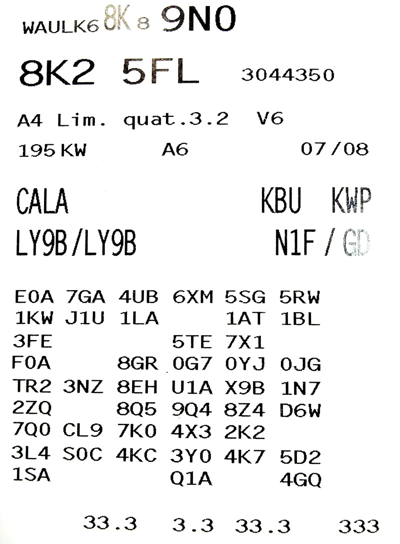
This PR code offers the following information:
- 8K2 5FL is the sales code that ElsaWin uses to identify the model.
- CALA is the engine code associated with the line “A4 Lim. Quat. 3.2 V6.â€
- KBU is the ElsaWin transmission code.
- The lower remaining 3-digit codes identify the options built into this model.
With a complete scan and the PR code, this A4 is completely identified.
The gateway identifies this model with controller malfunctions – see chart below.
| Controller Malfunctions |
|---|
| 01-Engine — Status: OK 0000 |
| 02-Auto Trans — Status: OK 0000 |
| 03-ABS Brakes — Status: Malfunction 0010 |
| 04-Steering Angle — Status: OK 0000 |
| 05-Acc/Start Auth. — Status: Malfunction 0010 |
| 09-Cent. Elect. — Status: Malfunction 0010 |
| 09-Cent. Elect. — Status: Malfunction 0010 |
| 10-Park/Steer Assist — Status: OK 0000 |
| 14-Susp. Elect. — Status: Malfunction 0010 |
| 15-Airbags — Status: OK 0000 |
| 16-Steering wheel — Status: Malfunction 0010 |
| 17-Instruments — Status: OK 0000 |
| 19-CAN Gateway — Status: OK 0000 |
| 1B-Active Steering — Status: Malfunction 0010 |
| 2E-Media Player 3 — Status: OK 0000 |
| 36-Seat Mem. Drvr — Status: Malfunction 0010 |
| 3C-Lane Change — Status: Malfunction 0010 |
| 42-Door Elect, Driver — Status: Malfunction 0010 |
| 46-Central Conv. — Status: Malfunction 0010 |
| 47-Sound System — Status: Malfunction 0010 |
| 52-Door Elect, Pass. — Status: Malfunction 0010 |
| 53-Parking Brake — Status: OK 0000 |
| 55-Headlight Range — Status: OK 0000 |
| 56-Radio — Status: Malfunction 0010 |
| 62-Door, Rear Left — Status: Malfunction 0010 |
| 72-Door, Rear Right — Status: Malfunction 0010 |
| 77-Telephone — Status: OK 0000 |
The article will break the list of controller faults into sections and in order of importance.
Primary on the list is the no start condition. Cranking was evident with a charged battery and the car appeared to have compression with no fault codes at the ECM.
Where to Start
A quick and simple cranking vacuum test offered no indication of any PCV or oil separator damage and there was one anomaly — no dipstick. It would appear the “pretend plug†is an option and oil measurement is via instrument cluster display. A special tool called a “Chrysler transmission dipstick†was employed to measure a heavily over filled crankcase.
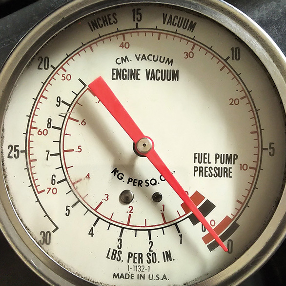
On this FSI model it is rather difficult to test fuel pressure and this is not advisable unless specific adapters and a liquid filled pressure gauge are attached to the high pressure rail and another setup at the low pressure side. It is NOT advisable.
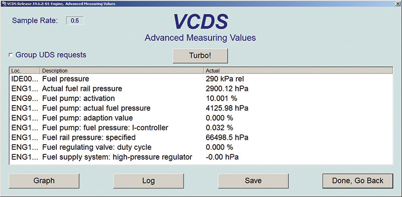
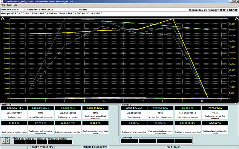
This model employs a SIMOS engine controller, and the measured values that may be used to are definitely going to look different. Modern VW and Audi vehicles will use UDS (Unified Diagnostic System) to request data.
This method is the safest test to measure fuel pressure but will offer some unique views to test, graph and measure the known values for fuel pressure without opening the fuel system. When the values are in the display, these choices are “tickedâ€:
- Fuel pressure
- Actual fuel rail pressure
- Fuel pump: activation
- Fuel pump: actual fuel pressure
- Fuel pump: adaption value
- Fuel pump: fuel pressure: I-controller
- Fuel rail pressure: specified
- Fuel regulating valve: duty cycle
- Fuel supply system: high-pressure regulator
These are static values with KOEO and saved with a screen image.
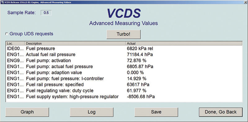
Sitting in the vehicle with the laptop or tablet, these values offered a hint that the fuel system was operating, but is there another view that will offer “pressure build up†versus cranking time? Saved again with a screen image but used the “Log†button.
The logs are saved within the C:\Ross-Tech\VCDS\Logs folder and read with the Microsoft Excel application.
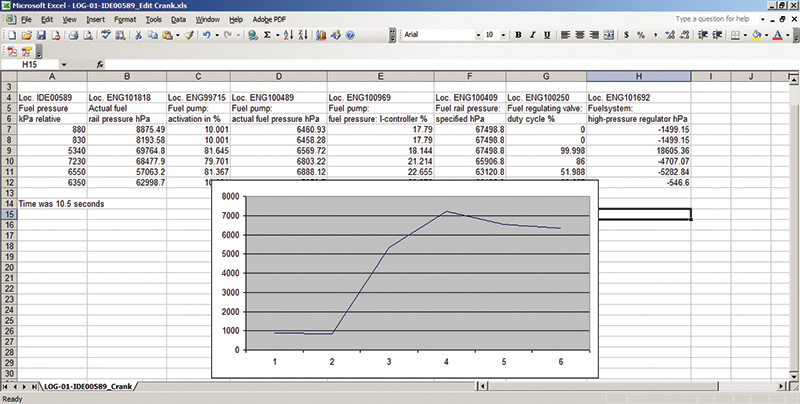
This method saved the log (for 10.5 seconds) and can refer to the log for more than one use. In this case: IDE00589 is fuel pressure kPa relative. The Excel graphing feature was used when highlighting the specific column IDE00589.
- Cranking values for 10.5 seconds
- From 880 kPa min. to 6550 kPa max.
- The translation for non System International (SI) users aka metric to psi
- From 127.6 psi min. to 949.9 psi max. (and that’s just cranking rpm)
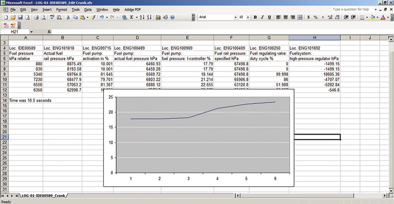
The next test was with another ID of interest: ENG100969 Fuel pressure I-controller offered that the ECM was in control, attempting to increase pressure during the cranking stage.
The same log was used and graphed the specific column ENG100969.
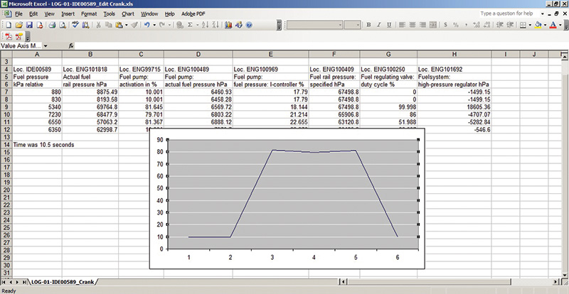
Lastly the internal fuel pump within the fuel tank ID ENG99715 is the ECM command via fuel pump control module during a cranking event.
Diagnostics from the driver’s seat and the engine may not have started, but at least the fuel system operated as intended. It’s assumed there was decent fuel in the tank.
Next step
No engine faults, there was rpm indicated with VCDS and the battery needed to be charged but likely failed. Minus 25 degrees C and in the middle of nowhere without any way of getting this A4 out of the elements, the bet was severe flooding.
And so it was, dripping wet spark plugs and the crankcase contaminated with fuel. This lesson in the facility was to use VCDS to the maximum as an aid to determine the likely condition of the no start, the cause, and the correction. The most important part of the lesson was to NOT open the fuel system but to graph the collected data. TEST compression!
The wait was on the replacement plugs but is there another method to view the fuel system status? With this tool, the access and graphing was faster and worked as intended.
Use this link only: https://mega.nz/file/KDohADhB#oQhdeUg55wmZU7YZcWaGk8i5gJyatGNMlQocRRLzwYw
Read the operating instructions within the compressed file.
Fresh spark plugs, fresh oil with an oil filter and a new battery had this engine running but with a few oddities after a hoist inspection.
One issue noticed was a contaminated CAT converter and a complaining trim fault.
The faults and freeze frame were as follows:
| 1 Fault found: |
| 6209 – Fuel Trim: Bank 1 (Add) P1137 00 [039] – System too rich Not Confirmed – Tested since memory clear |
| Freeze Frame: |
| Fault Status: 00000001 |
| Fault Priority: 2 |
| Fault Frequency: 1 |
| Mileage: 194154 km |
| Date: 2020.02.06 |
| Time: 19:32:12 |
| Engine speed: 695.00 /min |
| Normed load value: 22.4 % |
| Vehicle speed: 0 km/h |
| Coolant temperature: 99 degrees C |
| Intake air temperature: 38 degrees C |
| Ambient air pressure: 970 mbar |
| Voltage terminal 30: 14.015 V |
| Unlearning counter according OBD: 40 |
| Engine speed: actual: 704 /min |
| MAF_ENVD: 125.28235 mg/stroke |
| Coolant temperature (unfiltered): 99.8 degrees C |
| Engine: operating status: IS |
| T_AST_ENVD: 2133.10 s |
| STATE_LS_ENVD[0]: 2 |
The cure was gentle driving on the side streets, allowing the CAT to come to temperature and deleting the fault. It took a few driving periods and tries with setting the throttle body at basic settings after every deletion, but the trim fault didn’t return. Battery removal also included the setting of readiness monitors, any adaptations such as one-trip window operation, clock and radio settings with HVAC adaptation.
What about the hoist inspection?
This A4 came to the lab on a flat bed and one fault repeated with:
| Shop #: WSC 93117 999 84391 < This is the shop that last worked on the suspension |
| Part No SW: 8K0 907 364 HW: 8K0 907 364 |
| Component: DAEMPFUNGS-SG H08 0052 |
| Revision: 00000000 Serial number: 06060802290003 |
| Coding: 050181 |
| Shop #: WSC 93117 999 84391 < This is the shop that last worked on the suspension |
| 2 Faults Found |
|---|
| 01769 – Sensor for Vehicle Leveling; Front Right (G289) 007 – Short to Ground |
| 03262 – Comfort Restriction |
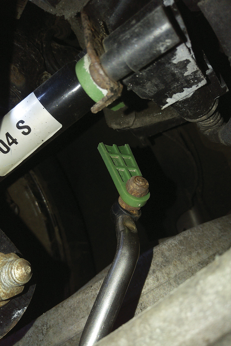
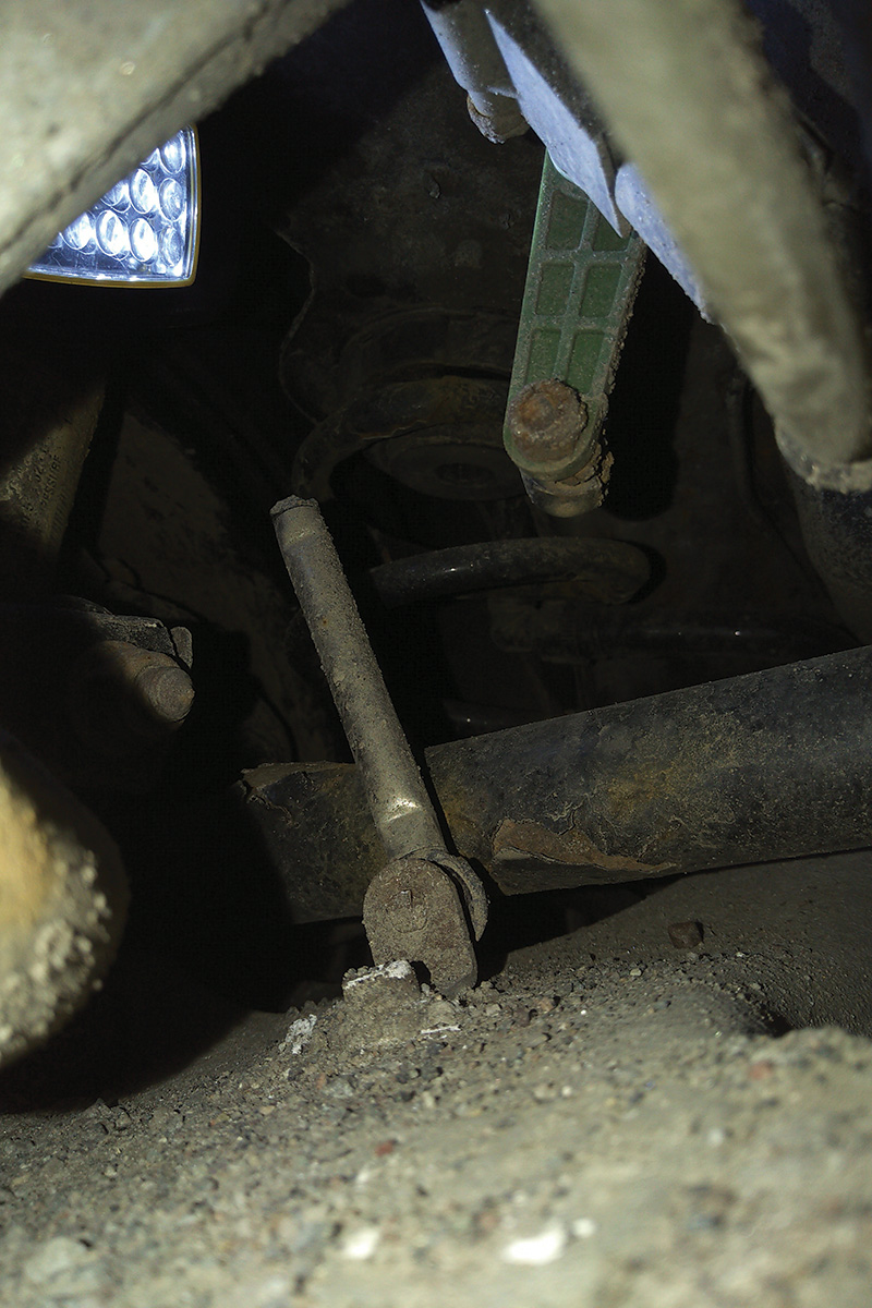
Unfortunately there were a few marks on the lower control arms when dragging the A4 onto the flatbed. A fresh break was found at the right front sensor, and the marks aligned with the damaged component.
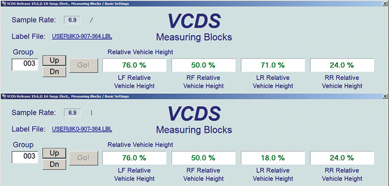
With a decent label created and now measuring the system via hoist up and down movements, other damage was found but no fault recorded. The images indicate a movement at the left rear sensor and this time with hand movements.
Indicated in Group 003, field 4 (71.0 percent and 18.0 percent)
This simple test could be accomplished with one or more sensor arms disconnected and by viewing the percentage changes.
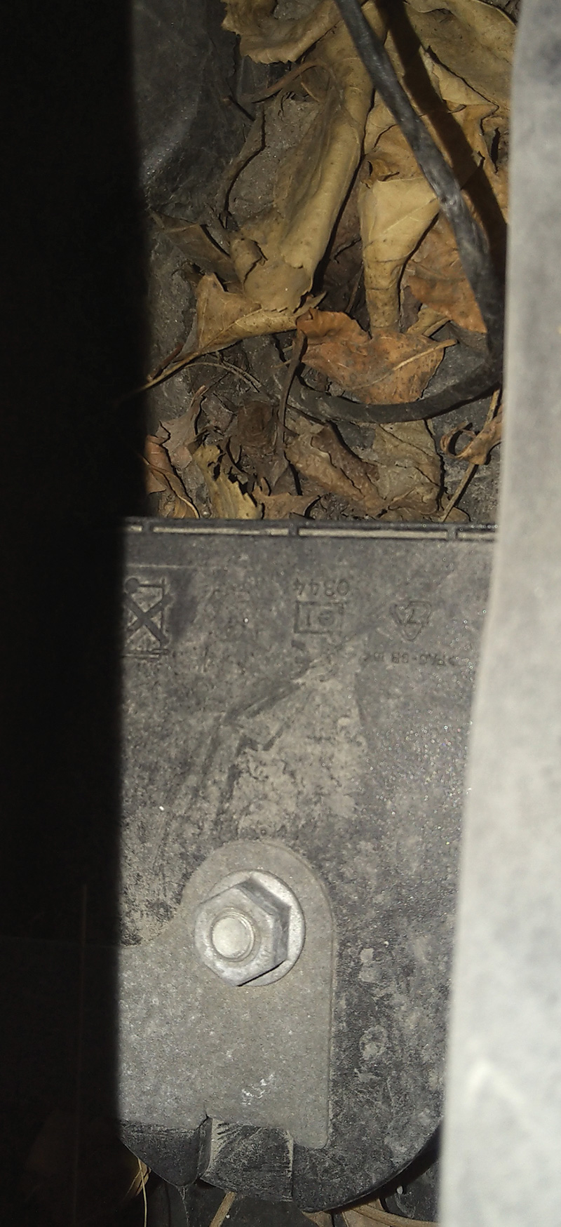
This damage was not created by the tow vehicle; this is called rust/salt and not looking after or maintaining the A4.
Proper maintenance should have been carried out much earlier on this A4. Removing the covers at the wiper, this time the cowl area was cleaned because of the buried LIN activated horn. The area may not have been cleaned for a very long time, likely producing a composting effect and interior smells.
The operation and cleaning was preventive.
At address 46, viewed was Component: LIN BACKUP HO H03 1301
Search an earlier article for a damaged no start because of a shorted LIN horn: Tips and Tricks with a 2008 Audi A6 3.2L no crank/no start.
This next controller was addressed when completing the cowl maintenance and viewing the buried harnesses and ground points.
| Address 1B: Active Steering (J792) Labels: None << One had to be made as an aid |
| Part No SW: 8K0 907 144 B HW: 8K0 907 144 B |
| Component: DYNAMIKLENK. H05 0490 |
| Revision: 50000003 Serial number: ——————— |
| Coding: 8C0000 |
| 2 Faults Found: |
| 00446 – Function Limitation due to Under-Voltage 002 – Lower Limit Exceeded – Intermittent |
| 02538 – Function Restriction due to Overload 001 – Upper Limit Exceeded – MIL ON |
Finding some “low quality†booster cables in the front seat offered a view of what could have happened to the A4 and how many attempts were made over many days while trying to get this flooded FSI engine running. It would be safe to say that a new battery and resetting the A4 to factory specifications ensured that the upper faults didn’t return. The guide to learning this system was creating the label and watching how the system behaved over time.
Last but not least, there were these faults with:
| Address 3C: Lane Change Labels: None << One had to be made as an aid |
| Part No SW: 8K0 907 566 B HW: 4L0 907 566 B |
| Component: J0769_SWA_MasterH01 0040 |
| Revision: 00H01000 Serial number: 6PZ 009 014-13 |
| Coding: 0000001 |
| Shop #: WSC 02145 785 00200 |
| Subsystem 1 – Part No: 8K0 907 568 B |
| Component: J0770_SWA_Slave_H01 0040 |
| Subsystem 2 – Serial number: 6PZ 009 014-33 |
| Subsystem 3 – Serial number: 5F14.07.0800H010003CD10217ÿ |
| Subsystem 4 – Serial number: D10217ÿ |
| 1 Fault Found |
| 16365 – Control Module – Electrical Error; CPU 2 014 – Defective |
| Freeze Frame |
| Fault Status: 01101110 |
| Fault Priority: 3 |
| Fault Frequency: 1 |
| Reset counter: 118 |
| Mileage: 104114 km |
| Time Indication: 0 |
| Date: 2016.03.31 |
| Time: 13:23:47 |
Explanation
The freeze frame option with the scan tells an interesting story about the fault and when it occurred.
| Fault Priority Numbers | |
|---|---|
| No. | Meaning |
| 0 | Undefined by manufacturer. |
| 1 | The fault has a strong influence on driveability, immediate stop is required. |
| 2 | The fault requires an immediate service appointment. |
| 3 | The fault doesn’t require an immediate service appointment, but it should be corrected with the next service appointment. |
| 4 | The fault recommends an action to be taken, otherwise driveability might be affected. |
| 5 | The fault has no influence on driveability. |
| 6 | The fault has a long term influence on driveability. |
| 7 | The fault has an influence on the comfort functions, but doesn’t influence the car’s driveability. |
| 8 | General Note |
Fault Frequency indicates the number of times the conditions that caused the fault have repeated during all driving cycles. This specific frequency occurred once and the customer called immediately, having the fault addressed the next day. The fault counts went from 0 to 254 and added increments with each drive cycle occurrence.
The Reset Counter is preassigned to each fault. If there are fault free driving cycles and the fault does not return, the counter will reset to the next lower number with every key cycle.
When having the final conversation with the vehicle owner, a question was asked about an accident at the rear of the A4 and mentioned a date with the average km at that time.
Current mileage is 194,150 km and the damage registered at that time was 104,114 km.
The A4 owner wondered how it was possible to have that data but opted out of the recommended and additional repairs for the moment.
Invoice accordingly
| Tools Used |
| VCDS with a 90 amp power supply |
| ElsaWin with screen capturing and movie software |
| Pen and paper with a simple camera |
Keep all the recordings and many have heard this before: “Ever since you touched it.â€
The point being, the A4 runs great with faults recorded at Suspension Electronics and Lane Change Electronics. The images and recording are proof over time.


0 Comments