
Keeping your eyes on the road and your hands on the wheel
The 1937 Mercedes-Benz 540 K Cabriolet featured one of the automotive industry’s earliest production car radios. What was then a premier product for owners of luxury vehicles has now become one of many components that aggregate vehicle performance data, real-time road condition information, and entertainment into one system. These newest infotainment systems combine several formerly standalone capabilities, including applications for navigation, vehicle functionality, communications, and multimedia entertainment.

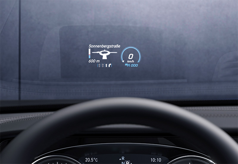
Available since 2014, the Mercedes-Benz Head-up Display (HUD) projects much of that information onto the windshield to help reduce the need for the driver to take his or her eyes off of the road ahead. The HUD projects speed, navigation, driver assistance, and other driving-relevant information onto an area of the windshield where it is easily viewed without obstructing the line-of-sight to the road ahead. Note that it’s not a “heads-up†display, but a head-up display.
The information presented varies based on how the vehicle is equipped, e.g. DISTRONIC adaptive cruise control, COMAND navigation system, etc., and the operator’s display preferences. The driver can adjust the position and brightness of the display on the windshield, and may also select which information he or she would like displayed. However, the HUD can display only information that is also available on the instrument cluster.
On Mercedes-AMG vehicles equipped with HUD the driver can select “Race Timer†to see the lap number and lap time in the HUD. On vehicles with “AMG Track Pace,†the HUD can display further details including speed and gear indication, lap and sector times, acceleration and braking, graphic track layout, and other information.
HUD operation
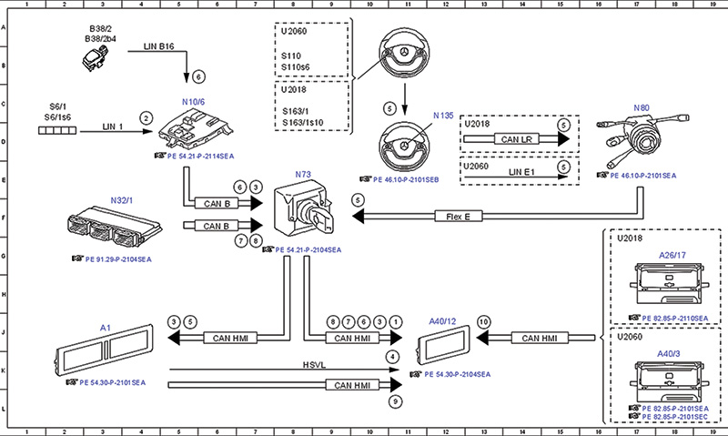
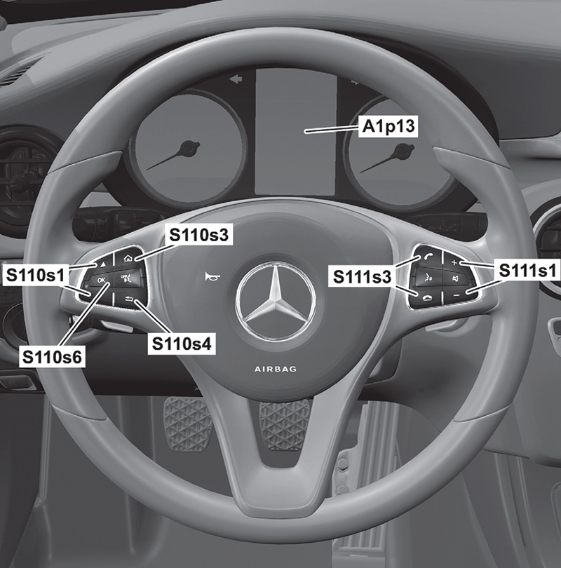
Drivers use buttons on the multifunction steering wheel to operate or change settings for the HUD. For this description, we’ll be using the S-class as of MY18 as an example, but the system is similar in all models. The driver can use the finger navigation pad (S163/1s10 in the HUD electrical function schematic) on the instrument cluster multifunction steering wheel button group (S163/1). Alternatively, they can use the OK button (S110s6) in the left multifunction steering wheel button group (S110).
The steering wheel electronics (N135) read user inputs to the button group and transmit those to the steering column module control unit (N80) via the steering wheel CAN (CAN LR), or for older models through the steering LIN (LIN E1). The steering column module control unit sends signals over the suspension FlexRay (Flex E), through the electronic ignition lock control unit (N73) and the user interface CAN (CAN-HMI) to the instrument cluster (A1). The instrument cluster then sends display data over CAN-HMI to the HUD.
Personalized choices can be saved on vehicles with memory function capability, for retrieval by different drivers. A driver can save different profiles, for example, one for routine weekday commutes, and another for weekend racetrack fun.
Driver height and seat position affect the position on the bottom third of the windshield where the driver can best see the HUD images. When the driver saves their preferred head-up display placement, algorithms in the HUD look at the image position on the windshield and the distance to the HUD control unit and triangulate to determine the location of the driver’s head. The “head motion box,†as Mercedes-Benz engineers call the area, allows the system to save in memory a mathematical description of that driver’s unique location for the HUD image. For each different driver who saves his or her preferred windshield location for the HUD display, the head-up display controller can access and act upon that saved description.
In Mercedes-Benz models with Memory Package (Code 275), this mathematical description is saved in combination with the driver’s preferred seat position. So, if the customer complaint is that the HUD image is not as easy to see as it once was, one thing to explore is whether the driver has changed his or her seat settings without also adjusting their preferred location of the HUD projection on the windshield. Seeing the display from even only a slightly different angle may make it appear blurry, distorted, or less bright.
The request to save or retrieve the memory position is transmitted by the driver seat control unit (N32/1) via the interior CAN, electronic ignition lock control unit and user interface CAN to the head-up display. To confirm the settings being saved, the instrument cluster control module emits a beep tone through its speaker.
Basic requirements for the HUD and memory save/recall functions in Mercedes-Benz models 217 and 222 (with Code 463: Head-up Display) to operate correctly, include that there is no over- or under-voltage condition, the ignition (Circuit 15) is ON, and the seat adjustment is normalized. Check the repair instructions in the Mercedes-Benz Workshop Information System (WIS) for specific vehicle applications, as different conditions may exist for saving seat and mirror adjustment settings to memory.
Saved head-up display settings may be retrieved by activation of user-profiles via the multimedia system control. The head-up display control unit then recalls the previously stored settings to lay out the desired content, position, and brightness of the image on the windshield.
Transmitting high-speed video
The instrument cluster control unit calculates the image information requested for the head-up display and sends it over a High-Speed Video Link (HSVL) to the HUD. Before it transmits the image information, the instrument cluster controller must convert the data to a format that is acceptable to the HSVL and its software. The head-up display includes a “warping matrix†that talks to the instrument cluster’s “warping engine,†which is a fancy way of saying that it has software that tells the instrument cluster how to process visual information for display on a non-flat surface. The warping engine ensures that the head-up display image does not appear distorted when it is projected onto the windshield.
If you replace the instrument cluster or the head-up display, you must also recalibrate the HUD so the “warping matrix†is updated in the instrument cluster control unit, and to allow both devices to communicate with each other. Similarly, if you replace the windshield, you must also recalibrate the HUD. Make sure the correct windshield is installed: a non-HUD windshield will display a double image because it doesn’t have the special coating required for the HUD. Genuine Mercedes-Benz glass will ensure you don’t have to repeat the job.
You can perform the basic recalibration using the workshop menu in the instrument cluster. Don’t skip this step. Otherwise your customer may see a distorted HUD image — one that might be reminiscent of a badly corrupted hologram in an old space adventure television show.
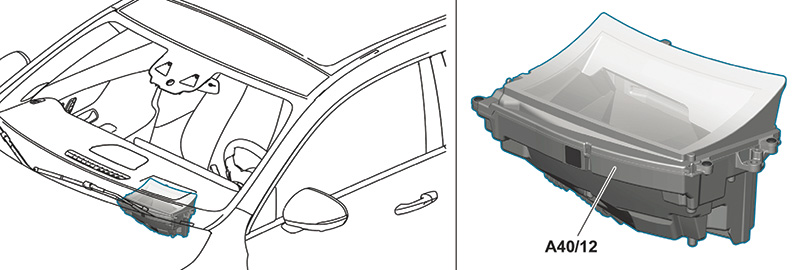
The instrument cluster control unit is placed in different locations depending on the vehicle model. For example, on the Mercedes-Benz CLA Coupe, front-wheel-drive subcompact (Model X118), the instrument cluster control unit (N133/1) is located under the driver’s seat. On the third-generation Mercedes-Benz GLS full-size luxury SUV (Model X167) which began production in October 2019, the instrument cluster control unit (N133/1) is located behind the instrument panel on the driver’s side. On the new all-electric EQC (Model N293), the instrument cluster control unit (N133/1) is located in the front passenger footwell behind the footrest.
Check head-up display function
To check or adjust the head-up display, first put the vehicle in ready-to-drive condition. That means set tire pressure at the factory specification, ride height to the normal level, and the steering wheel in the straight-ahead position. Correct values for these parameters help ensure that the head-up display accurately represents the vehicle position relative to the road. Close the engine hood, doors, and trunk lid.
Insert the SmartKey into the ignition and turn it to position 1. For vehicles with KeylessGO, with the key in the passenger compartment and the brake pedal not engaged or pressed, press the Start button once. Either of these actions should switch Circuit 15R on. Adjust the driver seat to your preferred position, then check the head-up display.
Check the HUD manually
You can check the head-up display manually on models with Code 463 for head-up display. This includes Models 205, 217, 222, and 253 with Code 463. The manual process uses buttons on the steering wheel to check and, if necessary, modify head-up display settings. XENTRY Diagnosis can also be used for this process.
Different Mercedes-Benz models may have variations in the exact procedure to access and modify settings for the head-up display, so check in the Workshop Information System (WIS) for the work instructions that apply to the vehicle you have in your bay. For example, look for WIS document number AR54.30-P-6401-02LW entitled “Check Head-up Display†for detailed step-by-step instructions to access HUD display settings on Models 205, 217, 222, and 253 (all with Code 463).
As you follow the WIS instructions, you will call up the first test image to begin the diagnostic process. Here we’ll start at the point when the first image is shown, using Models 205, 217, 222, and 253 as our example.

Test image 1 is an example of typical HUD information displayed to the driver (here using German and metric units). If test image 1 displayed by the HUD appears correctly – the instructions advise using two different persons to assess the image – confirm the settings as follows: Press OK (S110s6), press the Scroll Forward/Back button (S110s1) repeatedly until “OFF†(original picture) is highlighted, and confirm the selection by pressing OK again. Press and hold the Back button (S110s4) for approx. 5 seconds. The test is complete and you can now exit the workshop menu.
If the image display was not correct, the WIS work instructions lead you through the detailed steps to identify and correct display problems. This involves a second test pattern display, along with several steps to take for alignment. If the image is still incorrect after all the parameters are reset, you will need a XENTRY Diagnosis machine to adjust the system, although this is rarely the case.
If any of the graphics are missing from test image 1, the information from the instrument cluster control unit may not be reaching the HUD. There could be a loose, broken, or damaged wire or connector somewhere in the circuit between the instrument cluster control unit and the HUD. Similarly, a problem with the High-Speed Video Link (HSVL) could be the cause of one or more elements not appearing properly in test image 1.
Before digging into wiring diagrams and fault codes, try to rule out simple misalignment issues. Just as a pinched optic nerve can cause eyesight problems, misalignment or distortion may cause test image 1 to display improperly. The WIS work instructions lead you through the detailed steps to identify and correct image alignment or distortion problems using buttons on the steering wheel.
After finding test image 1 not displaying properly, continue to the next step: Still in the workshop menu, press the OK button, then tap the Scroll Forward/Back button repeatedly until “Test Image 7†is highlighted. Click OK to confirm the selection of test image 7. Again, the WIS instructions advise that the image is to be evaluated by at least two persons.
This test image is a horizontal rectangular grid with a large bullseye in the center. The rectangle represents the space where the HUD projects all information to the driver. The HUD settings are OK if test image 7 displayed at the windshield is centered and not skewed or distorted in any way. If test image 7 appears correct to both persons, the settings are OK. Confirm this by pressing the OK button (S110s6). Next, press the Scroll Forward/Back button (S110s1) repeatedly until “OFF†(the original picture) is highlighted, then press OK to confirm that you want to turn off the test image. Last, hold down the Back button (S110s4) for approximately five seconds. The correct settings are saved and you can exit the workshop menu.

Any HUD image other than a perfectly centered, non-distorted test image 7 means you need to reset the parameters in the workshop menu. To do this, press the Back button, then tap the Scroll Back/Forward button until “Parameters†is highlighted. Press OK. Then scroll until “Warp configuration†is highlighted and press OK. You have just reset the HUD parameters.
Now, call up test images 1 and 7 again. If they are now undistorted and correct, press OK (S110s6), press the Scroll Forward/Back button (S110s1) repeatedly until “OFF†(original picture) is highlighted, and confirm the selection by pressing OK again. Press and hold the Back button (S110s4) for approximately 5 seconds. The test is complete and you can now exit the workshop menu.
Again, if the manual reset of the parameters using the workshop menu does not adequately correct the display issues, you will need a XENTRY Diagnosis machine to adjust the system.
The head-up display system has been proven over the years to be extraordinarily reliable. Dealers report few problems.
One issue that has been seen was when the customer had an aftermarket windshield installed — one that was not properly set up for the HUD. A correct windshield has a coating that prevents a double reflection — one from each side of the glass — from displaying. Incorrect glass shows a double reflection, making the HUD virtually useless.
The only other issue we heard of was a damaged HSVL cable. A technician was working behind the dash on a different problem and accidentally damaged the wire. Mercedes-Benz has replacement cables available just in case this happens.
Just as the head-up display makes it easy for drivers to keep their eyes on the road, Mercedes-Benz engineers have made it simple to test and reset a distorted HUD image using, in most cases, just a menu within the instrument cluster. While we don’t expect you’ll ever have to work on one of these systems. Just in case, we’ve provided you with just about everything you’ll need to know for fast and easy repairs.


0 Comments